US2791663A - Alarms - Google Patents
Alarms Download PDFInfo
- Publication number
- US2791663A US2791663A US482709A US48270955A US2791663A US 2791663 A US2791663 A US 2791663A US 482709 A US482709 A US 482709A US 48270955 A US48270955 A US 48270955A US 2791663 A US2791663 A US 2791663A
- Authority
- US
- United States
- Prior art keywords
- circuit
- building
- fuse
- alarm
- alarms
- Prior art date
- Legal status (The legal status is an assumption and is not a legal conclusion. Google has not performed a legal analysis and makes no representation as to the accuracy of the status listed.)
- Expired - Lifetime
Links
Images
Classifications
-
- G—PHYSICS
- G08—SIGNALLING
- G08B—SIGNALLING SYSTEMS, e.g. PERSONAL CALLING SYSTEMS; ORDER TELEGRAPHS; ALARM SYSTEMS
- G08B17/00—Fire alarms; Alarms responsive to explosion
- G08B17/06—Electric actuation of the alarm, e.g. using a thermally-operated switch
Definitions
- One type comprises a self-contained unit which may be placed in a suitable location in the building and consists of a thermally responsive element arranged to close a circuit to a bell or other form of signal when the temperature at the unit reaches a predetermined value.
- the bell may either be energized from a battery or wired into the house circuit.
- the battery In the first case, the battery must be periodically replaced or the alarm is not reliable.
- the necessary wiring involves more expense than the average homeowner is willing to assume, particularly in the event that maximum protection is desired by locating the alarm at strategic locations throughout the building to be protected which may be remote from the location to be protected.
- Another system utilizes a spring actuated bell which is automatically operated when the temperature at the device reaches a predetermined value.
- the length of time that the alarm will sound is necessarily limited and the spring may become unwound or break without the owner realizing it, thus adversely affecting the reliability of the device.
- the alarms are not readily located remote from the thermally responsive element without extensive wiring which further adds to the expense.
- the present invention has for its object the provision of an inexpensive but reliable alarm system which utilizes any existing electric light or power circuits in any electrically wired structure and can readily be installed therein at low cost.
- thermo-responsive switch elements are plugged into or connected to light sockets or appliance outlets at strategic locations within the structure, each element being arranged to cause a short in the circuit into which the element is connected whenever the temperature at the element reaches a predetermined value, causing the opening of a circuit interrupter which actuates an alarm powdered by the circuit betwen the interrupter and the source of supply to warn persons within or outside the structure of the impending danger.
- the system involves a novel circuit interrupter which, in response to an overload in the circuit, closes an auxiliary circuit in which the alarm is incorporated.
- Fig. 1 is a diagrammatic view of one form of system in which the invention is embodied
- Fig. 2 is a section through one of the elements of the system
- Fig. 3 is a section through another element of the system.
- the wires L1, L2 represent the usual power lines entering a building and passing to the usual fuse box 10.
- a circuit comprising wires 12, 14 is illustrated as servicing one portion of the building, such as the lower floor or basement, and another circuit 16, 18 services another portion of the building.
- Circuit interrupters or fuses 20 control the current through the wires 14, 18 for providing overload protection for-the two circuits.
- Each of the circuit interrupters is illustrated as comprising a base 22 formed of suitable electric insulating material and having a pair of contactor members 24, 26 as in the conventional screw type fuse.
- the contact members are electrically connected by a strip or wire 28 of fusible metal which melts upon the passage of a current of predetermined amperage therethrough to interrupt the current flow, and by a flexible connection 30.
- the fuse also includes means for closing another circuit when an overload in the controlled circuit causes the wire 28 to melt.
- a rod 32 of electrical insulating material guided for movement axially of the base 22 by an apertured plate 34 clamped between the base 22'and a head 36 secured to the base by a clamping ring 38.
- the outer end of the rod 32 carries a switch or conductor member 40 urged toward a pair of contact members 42 by a spring 44.
- the wire 28 holds the conductor member in the position illustrated against the action of the spring, but upon an overload in the controlled circuit suificient to cause melting of the wire 28, the spring 44 forces the conductor member 40 into engagement with the contact members 42 to establish a circuit through them.
- each of the circuits 12, 1.4, and 16, 18 are illustrated light bulb sockets and/or appliance outlets 45 into which may be connected any suitable electric appliance.
- temperature responsive fuse blowers 46 Connected into certain of the bulb sockets or appliance outlets are temperature responsive fuse blowers 46 which are arranged to cause a short in the circuit when the temperature in the vicinity of the fuse blower attains a predetermined value.
- One form which this fuse blower may assume is illustrated in Fig. 3 and is shown to comprise a base 48 of electrical insulating material carrying contact members 50, 52 adapted to be received in a conventional bulb socket.
- Connected to the members 5%, 52 are con ductors 54 having terminal portions 56 which lie adja cent to a conical internal portion of the base 43.
- a conical conductor 58 carried by a rod 60 guided in a plate 62 clamped between the base 48 and a head 64 secured in the base by a clamping ring 66.
- the conductor is held out of contact with the tcrminal portions 56 of the conductors 54 against the action of a spring 68 by a wire or link 70 of fusible metal secured between the rod 50 and the head 64.
- the head 64 may be apertured or be formed of an open ribbed construction so that the wire 70 is affected directly by the temperature of the ambient atmosphere, which will cause melting of the wire when the temperature reaches a predetermined value, thus permitting movement of the conductor 58 into engagement with the terminal portions 56, causing a direct short across the circuit in which the member 46 is con- Patented May 7, 1957 nected.
- a screen 72 covers the openings in the head 64 to protect the wire 70 without insulating it from the atmosphere.
- the fuse blowers 46 may either be of the screw-in type as shown, or may be provided with a pair of prong contact members for plugging into the conventional appliance outlet, or may be inserted into extension cords so that they may be located in any desir able spot in a room. Any desired number of fuse blowers may be inserted in a circuit to provide maximum protec tion for the building.
- a step down transformer 74 Connected to the lines L1, L2 on the input side of the fuse box is a step down transformer 74 to one side of the secondary of which are connected bells 76, 78 each of which is connected through contact members 42, 42 of the circuit breakers 20.
- the wire 28 in the circuit breaker controlling the particular circuit will melt, and the contact member 42 will be connected to complete a circuit through the associated bell 76 to warn an occupant or attendant of the building.
- Any other form of signal either visible or audible may of course be substituted for the bells illustrated, and because of their low voltage actuation, they may be located at any desired place within the building and connected into the system with a minimum of difliculty.
- Additional alarms 88 may be located outside of the building in parallel with the interior alarms and controlled by switches 82 so that if the building is to be left unoccupied and the switches are closed, the outside alarms will operate should a fire start within the building.
- a control which operates in response to an abnormally rapid rise in temperature may be substituted.
- the alarm may be operated either in response to the attainment of a predetermined temperature or in response to a rapid rise in temperature, either of which will reflect the presence of a fire in the vicinity of the control member.
- my system may also be employed as a burglar alarm system.
- all that is required is to replace or supplement the fuse blowers 46 by switch members which will close and short the circuits into which they are connected upon intrusion of unwanted persons within the building.
- switch members which will close and short the circuits into which they are connected upon intrusion of unwanted persons within the building.
- Such devices might be operated by opening of windows, walking on carpets etc., and disconnected from the circuit when burglar protection is not needed or desired.
- a circuit breaker comprising a body member formed of two parts, a partition between said parts forming two chambers, a pair of electrical contact members in an end wall of one chamber, a rod slidable through said partition toward said contact members, conducting means carried by an end of said rod arranged, when the rod is moved toward said end wall, to close a circuit through said contact members, a spring urging said rod toward said end wall, a pair of conductor members carried by the end wall of the other chamber of said body member, a fusible element connecting said other conductor members, said fusible element being connected to said rod and holding it away from the first-mentioned end wall against the action of said spring whereby, upon an overload in the circuit through the fusible element, the element will rupture, interrupting the circuit through said conductor members and permitting movement of the red by the spring and closure of the circuit through the contact members.
Landscapes
- Business, Economics & Management (AREA)
- Emergency Management (AREA)
- Physics & Mathematics (AREA)
- General Physics & Mathematics (AREA)
- Fuses (AREA)
Description
R. W. CABELL May 7, 1957 ALARMS Filed Jan. 19, 1955 y M m W M 0 m z 1T Q1 Q) M, v w M u w E INVENTOR. BY 61 w new United States Patent ALARMS Roger W. Cabell, Providence, R. I., assignor to Loretta E. Cabell and Laura W. Cabell, both of Providence,
Application January 19, 1955, Serial No. 482,709 1 Claim. (Cl. 200142) This invention relates to alarm systems for use in houses or other structure using electrical power, and is illustrated herein as embodied in a fire alarm system although it will be understood that the invention is also applicable to burglar alarm systems and the like.
Many types of fire alarm systems suitable for instal lation in existing dwellings have been proposed. One type comprises a self-contained unit which may be placed in a suitable location in the building and consists of a thermally responsive element arranged to close a circuit to a bell or other form of signal when the temperature at the unit reaches a predetermined value. The bell may either be energized from a battery or wired into the house circuit. In the first case, the battery must be periodically replaced or the alarm is not reliable. In the other case, the necessary wiring involves more expense than the average homeowner is willing to assume, particularly in the event that maximum protection is desired by locating the alarm at strategic locations throughout the building to be protected which may be remote from the location to be protected.
Another system utilizes a spring actuated bell which is automatically operated when the temperature at the device reaches a predetermined value. The length of time that the alarm will sound is necessarily limited and the spring may become unwound or break without the owner realizing it, thus adversely affecting the reliability of the device. With such systems, the alarms are not readily located remote from the thermally responsive element without extensive wiring which further adds to the expense.
Despite the appalling losses of life and property every year due to fires, and the desirability of providing a reliable fire alarm system in homes, apartments, etc., relatively few such systems have been installed, and the average homeowner is without any fire alarm protection even though aggressive efforts to mechandise such systems and others have been made. The present invention has for its object the provision of an inexpensive but reliable alarm system which utilizes any existing electric light or power circuits in any electrically wired structure and can readily be installed therein at low cost.
To this end and in accordance with a feature of the invention, thermo-responsive switch elements are plugged into or connected to light sockets or appliance outlets at strategic locations within the structure, each element being arranged to cause a short in the circuit into which the element is connected whenever the temperature at the element reaches a predetermined value, causing the opening of a circuit interrupter which actuates an alarm powdered by the circuit betwen the interrupter and the source of supply to warn persons within or outside the structure of the impending danger.
In accordance with a further feature of the invention, the system involves a novel circuit interrupter which, in response to an overload in the circuit, closes an auxiliary circuit in which the alarm is incorporated.
The above and other features of the invention, including novel details of construction and combinations of elements, will now be described with reference to the drawing and pointed out in the claim.
In the drawings,
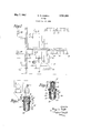
Fig. 1 is a diagrammatic view of one form of system in which the invention is embodied;
Fig. 2 is a section through one of the elements of the system, and
Fig. 3 is a section through another element of the system.
Referring to Fig. 1, the wires L1, L2 represent the usual power lines entering a building and passing to the usual fuse box 10. A circuit comprising wires 12, 14 is illustrated as servicing one portion of the building, such as the lower floor or basement, and another circuit 16, 18 services another portion of the building. Circuit interrupters or fuses 20 control the current through the wires 14, 18 for providing overload protection for-the two circuits.
Each of the circuit interrupters is illustrated as comprising a base 22 formed of suitable electric insulating material and having a pair of contactor members 24, 26 as in the conventional screw type fuse. The contact members are electrically connected by a strip or wire 28 of fusible metal which melts upon the passage of a current of predetermined amperage therethrough to interrupt the current flow, and by a flexible connection 30.
The fuse also includes means for closing another circuit when an overload in the controlled circuit causes the wire 28 to melt. For this purpose, to the inner end of the wire 28 is connected a rod 32 of electrical insulating material guided for movement axially of the base 22 by an apertured plate 34 clamped between the base 22'and a head 36 secured to the base by a clamping ring 38. The outer end of the rod 32 carries a switch or conductor member 40 urged toward a pair of contact members 42 by a spring 44. Normally however the wire 28 holds the conductor member in the position illustrated against the action of the spring, but upon an overload in the controlled circuit suificient to cause melting of the wire 28, the spring 44 forces the conductor member 40 into engagement with the contact members 42 to establish a circuit through them.
Across each of the circuits 12, 1.4, and 16, 18 are illustrated light bulb sockets and/or appliance outlets 45 into which may be connected any suitable electric appliance. Connected into certain of the bulb sockets or appliance outlets are temperature responsive fuse blowers 46 which are arranged to cause a short in the circuit when the temperature in the vicinity of the fuse blower attains a predetermined value. One form which this fuse blower may assume is illustrated in Fig. 3 and is shown to comprise a base 48 of electrical insulating material carrying contact members 50, 52 adapted to be received in a conventional bulb socket. Connected to the members 5%, 52 are con ductors 54 having terminal portions 56 which lie adja cent to a conical internal portion of the base 43.
Normally adjacent to but held out of contact with the terminal portions 56 is a conical conductor 58 carried by a rod 60 guided in a plate 62 clamped between the base 48 and a head 64 secured in the base by a clamping ring 66. The conductor is held out of contact with the tcrminal portions 56 of the conductors 54 against the action of a spring 68 by a wire or link 70 of fusible metal secured between the rod 50 and the head 64. The head 64 may be apertured or be formed of an open ribbed construction so that the wire 70 is affected directly by the temperature of the ambient atmosphere, which will cause melting of the wire when the temperature reaches a predetermined value, thus permitting movement of the conductor 58 into engagement with the terminal portions 56, causing a direct short across the circuit in which the member 46 is con- Patented May 7, 1957 nected. A screen 72 covers the openings in the head 64 to protect the wire 70 without insulating it from the atmosphere.
I It will be understood that the fuse blowers 46 may either be of the screw-in type as shown, or may be provided with a pair of prong contact members for plugging into the conventional appliance outlet, or may be inserted into extension cords so that they may be located in any desir able spot in a room. Any desired number of fuse blowers may be inserted in a circuit to provide maximum protec tion for the building.
Connected to the lines L1, L2 on the input side of the fuse box is a step down transformer 74 to one side of the secondary of which are connected bells 76, 78 each of which is connected through contact members 42, 42 of the circuit breakers 20. Thus, upon the existence of a short in either of the circuits caused by any of the fuse blowers by reason of a fire in its vicinity, the wire 28 in the circuit breaker controlling the particular circuit will melt, and the contact member 42 will be connected to complete a circuit through the associated bell 76 to warn an occupant or attendant of the building. Any other form of signal either visible or audible, may of course be substituted for the bells illustrated, and because of their low voltage actuation, they may be located at any desired place within the building and connected into the system with a minimum of difliculty.
Additional alarms 88 may be located outside of the building in parallel with the interior alarms and controlled by switches 82 so that if the building is to be left unoccupied and the switches are closed, the outside alarms will operate should a fire start within the building.
In addition to the usefulness of my system in providing fire protection to private dwellings, it is particularly useful in apartment buildings and the like, in which the circuits to the several apartments are controlled by a central fuse box. Such buildings often have an attendant or watchman in constant service, in which case all the alarms might be located in the vicinity of the fuse box, and the fuse blowers located wherever desired throughout the structure, thus providing adequate protection at small cost without having to string wires throughout the building. The same of course applies where a group of buildings, many of which are frequently left unattended, such as buildings on a farm, have electrical service controlled by a fuse box in the main building or house.
It will be understood that in place of the fuse blowers 46, which close the circuit in response to the attainment of a predetermined high temperature of the air surrounding them, a control which operates in response to an abnormally rapid rise in temperature may be substituted. Thus, the alarm may be operated either in response to the attainment of a predetermined temperature or in response to a rapid rise in temperature, either of which will reflect the presence of a fire in the vicinity of the control member.
It will be apparent that my system may also be employed as a burglar alarm system. In such case, all that is required is to replace or supplement the fuse blowers 46 by switch members which will close and short the circuits into which they are connected upon intrusion of unwanted persons within the building. Such devices might be operated by opening of windows, walking on carpets etc., and disconnected from the circuit when burglar protection is not needed or desired.
it is to be understood that my present invention is capable of exemplification in other and further modifications not shown or described in this application for Letters Patent, but all modifications insofar as they embody the principle of the present invention are to be deemed within the scope and purview of the appended claim.
What I claim as new and desire to secure by Letters Patent of the United States is:
A circuit breaker comprising a body member formed of two parts, a partition between said parts forming two chambers, a pair of electrical contact members in an end wall of one chamber, a rod slidable through said partition toward said contact members, conducting means carried by an end of said rod arranged, when the rod is moved toward said end wall, to close a circuit through said contact members, a spring urging said rod toward said end wall, a pair of conductor members carried by the end wall of the other chamber of said body member, a fusible element connecting said other conductor members, said fusible element being connected to said rod and holding it away from the first-mentioned end wall against the action of said spring whereby, upon an overload in the circuit through the fusible element, the element will rupture, interrupting the circuit through said conductor members and permitting movement of the red by the spring and closure of the circuit through the contact members.
References Cited in the file of this patent UNITED STATES PATENTS 1,068,440 McCarthy iuly 29, 1913 1,734,071 Blalack Nov. 5, 1929 1,813,844 Gilbert July 7, 1931 3 1,927,744 Jones Sept. 19, 1933 2,011,112 McBrien et a1 Aug. 13, 1935 2,085,386 Phillips et a1 July 29, 1937
Priority Applications (1)
| Application Number | Priority Date | Filing Date | Title |
|---|---|---|---|
| US482709A US2791663A (en) | 1955-01-19 | 1955-01-19 | Alarms |
Applications Claiming Priority (1)
| Application Number | Priority Date | Filing Date | Title |
|---|---|---|---|
| US482709A US2791663A (en) | 1955-01-19 | 1955-01-19 | Alarms |
Publications (1)
| Publication Number | Publication Date |
|---|---|
| US2791663A true US2791663A (en) | 1957-05-07 |
Family
ID=23917122
Family Applications (1)
| Application Number | Title | Priority Date | Filing Date |
|---|---|---|---|
| US482709A Expired - Lifetime US2791663A (en) | 1955-01-19 | 1955-01-19 | Alarms |
Country Status (1)
| Country | Link |
|---|---|
| US (1) | US2791663A (en) |
Cited By (1)
| Publication number | Priority date | Publication date | Assignee | Title |
|---|---|---|---|---|
| US3465280A (en) * | 1966-04-12 | 1969-09-02 | Bassani Spa | Fuse-holder |
Citations (6)
| Publication number | Priority date | Publication date | Assignee | Title |
|---|---|---|---|---|
| US1068440A (en) * | 1912-10-28 | 1913-07-29 | John J Mccarthy | Fire-alarm system. |
| US1734071A (en) * | 1927-07-18 | 1929-11-05 | Jacob L Blalack | Circuit-controlling device |
| US1813844A (en) * | 1929-04-26 | 1931-07-07 | Tyson H Gilbert | Circuit closing device |
| US1927744A (en) * | 1926-06-14 | 1933-09-19 | Chas Cory Corp | Signal or alarm system |
| US2011112A (en) * | 1931-07-24 | 1935-08-13 | Mcbrien | Electric alarm circuit |
| US2085386A (en) * | 1936-01-13 | 1937-06-29 | William J Phillips | Thermocircuit controller |
-
1955
- 1955-01-19 US US482709A patent/US2791663A/en not_active Expired - Lifetime
Patent Citations (6)
| Publication number | Priority date | Publication date | Assignee | Title |
|---|---|---|---|---|
| US1068440A (en) * | 1912-10-28 | 1913-07-29 | John J Mccarthy | Fire-alarm system. |
| US1927744A (en) * | 1926-06-14 | 1933-09-19 | Chas Cory Corp | Signal or alarm system |
| US1734071A (en) * | 1927-07-18 | 1929-11-05 | Jacob L Blalack | Circuit-controlling device |
| US1813844A (en) * | 1929-04-26 | 1931-07-07 | Tyson H Gilbert | Circuit closing device |
| US2011112A (en) * | 1931-07-24 | 1935-08-13 | Mcbrien | Electric alarm circuit |
| US2085386A (en) * | 1936-01-13 | 1937-06-29 | William J Phillips | Thermocircuit controller |
Cited By (1)
| Publication number | Priority date | Publication date | Assignee | Title |
|---|---|---|---|---|
| US3465280A (en) * | 1966-04-12 | 1969-09-02 | Bassani Spa | Fuse-holder |
Similar Documents
| Publication | Publication Date | Title |
|---|---|---|
| US3522595A (en) | Self-contained fire detecting and warning apparatus | |
| US3872355A (en) | Fire detection and projection circuit and device | |
| US3909814A (en) | Detecting and control method and apparatus | |
| US3644912A (en) | Alarm system | |
| US3320601A (en) | Combined fire sensing alarm and electric power receptacle | |
| US3510863A (en) | Apartment alarm | |
| US3786502A (en) | Security system | |
| US3045226A (en) | Theft detection system for television receivers or the like | |
| US1081884A (en) | Burglar-alarm. | |
| US2791663A (en) | Alarms | |
| US3603403A (en) | Automatic fire extinguishing apparatus | |
| US4754263A (en) | Burglar alarm system | |
| US2701874A (en) | Burglar alarm system | |
| US2916730A (en) | Alarm system | |
| US2107525A (en) | Fire detecting and alarm mechanism | |
| US4506254A (en) | Alarm system with detectors and signaling devices on the same cable pair | |
| US2866181A (en) | Burglar alarm having both visual and audible alarm means | |
| US3938121A (en) | Electrical wiring and alarm system | |
| US2202535A (en) | Wall box switch | |
| US3046536A (en) | Automatic fire alarm energizing means | |
| US3682250A (en) | Enclosed and confined area automatic fire extinguisher hose and apparatus | |
| US3801971A (en) | Telephone alarm system | |
| US1935611A (en) | Open circuit fire alarm | |
| US2704840A (en) | Fire alarm system | |
| US3234535A (en) | Combined burglar and fire alarm device |