US2781663A - Well fluid sampling device - Google Patents
Well fluid sampling device Download PDFInfo
- Publication number
- US2781663A US2781663A US559461A US55946156A US2781663A US 2781663 A US2781663 A US 2781663A US 559461 A US559461 A US 559461A US 55946156 A US55946156 A US 55946156A US 2781663 A US2781663 A US 2781663A
- Authority
- US
- United States
- Prior art keywords
- conduit
- tool
- fluid
- well
- bore
- Prior art date
- Legal status (The legal status is an assumption and is not a legal conclusion. Google has not performed a legal analysis and makes no representation as to the accuracy of the status listed.)
- Expired - Lifetime
Links
- 239000012530 fluid Substances 0.000 title description 33
- 238000005070 sampling Methods 0.000 title description 12
- 238000007789 sealing Methods 0.000 description 46
- 238000004891 communication Methods 0.000 description 16
- 230000015572 biosynthetic process Effects 0.000 description 9
- 239000004020 conductor Substances 0.000 description 4
- 239000000523 sample Substances 0.000 description 4
- 239000012267 brine Substances 0.000 description 3
- HPALAKNZSZLMCH-UHFFFAOYSA-M sodium;chloride;hydrate Chemical compound O.[Na+].[Cl-] HPALAKNZSZLMCH-UHFFFAOYSA-M 0.000 description 3
- 238000003466 welding Methods 0.000 description 3
- 238000010276 construction Methods 0.000 description 2
- 238000011835 investigation Methods 0.000 description 2
- 238000004519 manufacturing process Methods 0.000 description 2
- 230000007246 mechanism Effects 0.000 description 2
- 238000012856 packing Methods 0.000 description 2
- 238000012360 testing method Methods 0.000 description 2
- 239000008280 blood Substances 0.000 description 1
- 210000004369 blood Anatomy 0.000 description 1
- 239000004568 cement Substances 0.000 description 1
- 230000008859 change Effects 0.000 description 1
- 238000007796 conventional method Methods 0.000 description 1
- 230000008878 coupling Effects 0.000 description 1
- 238000010168 coupling process Methods 0.000 description 1
- 238000005859 coupling reaction Methods 0.000 description 1
- 230000000694 effects Effects 0.000 description 1
- 230000005611 electricity Effects 0.000 description 1
- 230000005484 gravity Effects 0.000 description 1
- 238000011065 in-situ storage Methods 0.000 description 1
- 239000007788 liquid Substances 0.000 description 1
- 230000005291 magnetic effect Effects 0.000 description 1
- 238000005259 measurement Methods 0.000 description 1
- 238000000034 method Methods 0.000 description 1
- 238000012986 modification Methods 0.000 description 1
- 230000004048 modification Effects 0.000 description 1
- 230000002093 peripheral effect Effects 0.000 description 1
- 230000035699 permeability Effects 0.000 description 1
- 230000001105 regulatory effect Effects 0.000 description 1
- 239000012858 resilient material Substances 0.000 description 1
- 230000000717 retained effect Effects 0.000 description 1
- 239000007787 solid Substances 0.000 description 1
- XLYOFNOQVPJJNP-UHFFFAOYSA-N water Substances O XLYOFNOQVPJJNP-UHFFFAOYSA-N 0.000 description 1
Images
Classifications
-
- E—FIXED CONSTRUCTIONS
- E21—EARTH OR ROCK DRILLING; MINING
- E21B—EARTH OR ROCK DRILLING; OBTAINING OIL, GAS, WATER, SOLUBLE OR MELTABLE MATERIALS OR A SLURRY OF MINERALS FROM WELLS
- E21B33/00—Sealing or packing boreholes or wells
- E21B33/10—Sealing or packing boreholes or wells in the borehole
- E21B33/12—Packers; Plugs
- E21B33/124—Units with longitudinally-spaced plugs for isolating the intermediate space
- E21B33/1243—Units with longitudinally-spaced plugs for isolating the intermediate space with inflatable sleeves
-
- E—FIXED CONSTRUCTIONS
- E21—EARTH OR ROCK DRILLING; MINING
- E21B—EARTH OR ROCK DRILLING; OBTAINING OIL, GAS, WATER, SOLUBLE OR MELTABLE MATERIALS OR A SLURRY OF MINERALS FROM WELLS
- E21B49/00—Testing the nature of borehole walls; Formation testing; Methods or apparatus for obtaining samples of soil or well fluids, specially adapted to earth drilling or wells
- E21B49/08—Obtaining fluid samples or testing fluids, in boreholes or wells
- E21B49/081—Obtaining fluid samples or testing fluids, in boreholes or wells with down-hole means for trapping a fluid sample
- E21B49/083—Samplers adapted to be lowered into or retrieved from a landing nipple, e.g. for testing a well without removing the drill string
Definitions
- This invention relates to an improved device for obtaining samples of well fluids from a well bore, and in particular concerns a device for taking samples of well fluids from a plurality of fluid-producing strata penetrated by a well bore and transporting said samples to the earths surface in substantially the same state as they occur in said strata.
- the producing formation extends over a very considerable interval and comprises a relatively large number of fluidA producing strata which lie closely adjacent to each other.
- the production interval it is not uncommon for the production interval to extend over 200 feet and to comprise 60-100 oil-producing, water-producing and non-producing strata all lying closely adjacent and even intermingled with one another.
- the location of the various strata and the nature of the fluid, if any, produced from each stratum be determined accurately. In the past, however, this has proved very diiiicult.
- Another object is to provide a device for accurately locating fluid-bearing strata traversed by a well bore.
- a further object is to provide a device for isolating, one from the other, a plurality of fluid-bearing strata traversed by a well bore and simultaneously taking samples of the uids produced by each of the isolated strata.
- each section is then taken out of communication with the bore hole, and the tool is raised to the surface Where each section may be examined for the presence of iluid and the nature thereof. Since the position which each of the tool sections previously occupied within the well bore is accurately known, the location of the duid-bearing strata along the length of the bore subjected to investigation can accurately be determined and the exact nature of the fluid produced by each of such .2,781,663 Patented Feb. 19, 1957 strata can readily be ascertained. Also, since each section was taken out of communication with the bore hole at the exact point where the uid flowed into such section, the iluid sample obtained at the earths surface corresponds exactly to the duid as it existed in the bore hole. Other means of employing the device of the invention are set forth hereinafter.
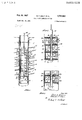
- Figure l schematically illustrates the operating principle of the device provided by the invention
- Figure 2 is a cross-sectional view of one form which the device may take
- Figure 3 is a fragmentary view showing how the device of Figure 2 is positioned within the well casing
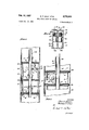
- Figure 4 is a cross-sectional view of one form which one of the elements of the device may take
- Figures 5 and 6 are cross-sectional views of other forms of the device embodying the principle of the invention.
- bore hole 10 is shown extending through a producing formation 11 containing Huid-bearing strata 12-16, inclusive.
- Well casing 17 is cemented within the bore by means of cement plug 18, and perforations 19 (formed, for example, by conventional gun perforation) extend through the walls of casing 17 and plug 18, thereby placing the inside of casing 17 in direct communication with the various strata tra-.
- the sampling tool of the invention rests within casing 17 on tool support 20 atxed to the inner Wall of casing 17 at a known depth.
- Said tool consists essentially of an elongated vertical supporting member 21 carrying a plurality of spaced horizontal separators 22 which engage the inner Wall of casing 17 at their peripheries to form fluid-tight seals therewith.
- Cylindrical shells 23 having an inside diameter larger than the diameter of supporting member 21 and provided with lateral perforations 24, extend between adjacent separators 22 which form fluid-tight seals therewith.
- positioning the tool within the casing effects division of the bore hole into a series of vertically stacked chambers or cells, each of which is defined by two of the separators 22, a shell 23, and a portion of supporting member 21, and each of which communicates: wlth a corresponding thickness of the formation via ⁇ perforation 24 in shell 23.
- a short conduit 25 carrying a valve 26 is to the earths surface through cable 28.
- tool support 20 which may take the form of a casing packer set by means of a wire line devlce, is positioned in casing 17 immediately below the portlon of formation 11 selected for investigation.
- the bottom of the hole itself may constitute the support for the tool.
- the well is then pumped dry and, if necessary, superimposed pressure may be applied to the caslng to prevent well fluids from entering the same while the tool is being placed in position.
- the tool is lowered into Ithe casing by means of cable 28 until it rests on tool support 20.
- each of separators 22 is caused to expand radially (by means hereinafter described) so as to form a fluid-tight seal at its periphery with the inner wall of casing 17.
- Valves 26 are then opened by suitable operation of control means 27 from the earths surface, thereby putting each chamber or cell of the tool into communication with that portion of the formation which it spans and allowing the well fluids produced therefrom to enter the corerspondng chamber. After a measured period of time, valves 26 are closed, the
- this information indicates that at 1595-1596 feet there occurs one or more brine-producing strata; at 1596-1598 feet there occurs one or more oilbearing strata; at 1598-1599 feet there occur both oiland brine-bearing strata; and at 1595-1600 feet there occurs one or more brine-bearing strata.
- the foregoing condsiderations are illustrative only, and do not necessarily represent the conditions in an actual producing formation; usually the production interval extends over a much greater length of the well bore and the tool employed will provide for considerably more than ve cells.
- the device therein shown consists of a central longitudinal conduit 30 which may be provided with means, not shown, for coupling to a well tubing string.
- Separators 31 are positioned along the length of conduit 30 in spaced pairs, the uppermost separator being welded or otherwise aixed to conduit 30, as at 32, but the remaining separators being free to slide along conduit 30.
- the lowermost of separators 31 is retained on conduit 30 by a pin or other clamping means 33 which holds the entire assembly together while the tool is being lowered into the well casing.
- Each separator 31 conveniently takes the form of a flat disc having a center hole corresponding closely to the diameter of conduit 30 and having a diameter somewhat less, say 1/2, than that of the internal diameter of the well casing in which the tool is to be employed. The latter is indicated by dotted lines 34.
- a resilient sealing means 35 in the form of a flat disc having a center hole closely corresponding to the outside ⁇ diameter of conduit 30 and a diameter corresponding closely to the inside diameter of casing 34, occupies ⁇ the space between each two separators which constitute a pair.
- Each pair of separators 31 is separated, one pair from the other, by a cylindrical shell or tube 36 which is of substantially the same outside diameter as that of separators 31 and which engages yopposed separators 31.
- edges of shells 36 and the faces of separators 31 are machined so that a fluid-tight seal is formed upon mere frictional engagement, thereby simplifying assembly and disassembly of the device, but if desired shells 36 may be positively sealed to separators 31, as by welding.
- each of shells 36 is provided with a lateral perforation 37
- conduit 30 is provided with a similar perforation 38 between each pair of separators 31
- the tool illustrated by Figure 2 consists of a longitudinal stack of isolated cells, each of which is defined by imperforate end ⁇ portions constituted by opposed separators 31, an outside walll constituted by shell 36 perforated at 37, and an inside Wall constituted by a portion of conduit 30 perforated at 38, and each separated from its adjacent cell by resilient sealing means 35 in the form of a septum.
- conduits 39 and 40 are in register with perforations 38 and 37, respectively, and lead to a double solenoid valve 41.
- valves 41 places the interior of conduit 30 in communication with each of the cells via conduits 39 and ports 43 and 43a, and also places each cell in communication with the well bore via conduits 40 and ports 42 and 42a.
- a telemetering device 46 for transmitting data to the earths surface via electrical conductor 47.
- Such device may take the form of a pressure tap or thermocouple to permit determining the pressure or temperature of the contents of each cell while the tool is positioned in the bore hole.
- the construction of such devices is well known in the art of bore hole measuring and testing.
- telemetering device 46 may be replaced by a recording thermometer or presure gauge in which the data are recorded on a chart driven by a clockwork or other timing mechanism.
- Figure 3 illustrates the tool of Figure 2 positioned within a well bore.
- Tool support 48 is welded or otherwise axed to the inside of well casing 34 which has been perforated as at 49, and ⁇ the device of Figure 2 has been run down the casing until the lowermost of separators 31 rests on support 48.
- resilient sealing means are compressed and expand laterally to form fluid-tight lseals with well casing 34, as at 49a.
- the well bore is divided laterally into a plurality of isolated cylindrical chambers of relatively short length, ⁇ and ythe total flow of fluid from the strata spanned by the tool is subdivided into separate streams.
- each stream of fluid enters a separate chamber of the tool via perforations 49 and 37, conduit 40, valve 41, and ports 42 and 42a, driving out the air through port 43a, valve 41, and conduit 39 into conduit 30.
- the pressure and temperature of each stream of uid is simultaneously taken by means of telemetering device or recording gauge 46.
- valves 41 are subsequently closed and the tool is raised -to the earths surface where an examination of the contents of each chamber will establish the nature thereof and the rate at which it ilowed into the tool.
- the location of each fluid stream with respect to the position of tool support 48 is readily determined from the dimensions of the particular tool.
- Said valve (shown in open position) consists of a hollow body portion 50 having an internal wall 51 dividing its interior into two chambers 52 and 53. Each chamber communicates with the exterior via ports 42, 42a, 43 and 43a. Within each chamber, a valve core 56 provided with an upwardly extending valve ⁇ stem 57 is free to reciprocate in a vertical direction. The length of core 56 is such that at the lower limit of lits travel it covers ports 42 and 43, and its diameter ⁇ is such as to form a fluidtight t with the walls of the chamber in which it is contained. If desired, packing rings (not shown) may be employed to insure such a tit.
- a hollow solenoid coil 58 is mounted -in the upper part of each chamber in such manner that valve stem 57 is pulled upwardly by the mag netic eld generated Whenthe solenoid coil is energized.
- Conductors 59 supply electrical energy to solenoid coils 58 from an exterior source, not shown, and may be so connected through switching means that both of coils 58 can be energized separately or together.
- coils S8 when coils S8 are energized, cores 56 are pulled upwardly, as shown, thereby placing port 43 in communication with port 43a and port 42 in communication with port 42a.
- valves 41 when valves 41 are connected as shown in Figure 2 and solenoid coils 58 are energized, well fluids can enter the chamber of the tool via perforations 37, conduits 40, portsl 42, chambers 53 and ports 42a, while displacing air from the chamber into conduit 30 via ports 43a, chambers 52, ports 43, conduits 39, and perforations 38.
- FIG. 5 represents another form which the device of the invention may take.
- Central longitudinal conduit 60 carries conical Wedges or cams 61 having their apexes directed downwardly spaced at intervals along its length. Said wedges may be integral with conduit 60, as shown, or may take the form of conical collars axed to conduit 60, as by welding.
- Resilient sealing means 62 take the form of relatively thick circular discs having a diameter slightly less than the diameter of perforated well casing 63 in which the device is employed, and being provided with a central hole having a diameter slightly larger than the outside diameter of conduit 60.
- sealing means 62 is mounted on conduit 60 immediately below ea-ch of wedges 61 so that the apex of the latter is in register with the central hole of sealing means 62.
- Cylindrical shells 64 having a diameter slightly less than that of sealing means 62 and having a perforation 65 extending laterally through their walls extend between the opposed faces of adjacent sealing means 62, and register in peripheral grooves 66 cut in the faces of sealing means 62.
- Bottom plate 67 is axed at the lower end of conduit 60, as by welding at 68, and serves as clamping means to hold the assembly together.
- Perforations 69 extend laterally through the walls of conduit 60 between wedges 61.
- the device of Figure thus takes the form of a series of isolated fluid-tight cylindrical chambers strung along the length of conduit 60, each of said chambers being defined by the opposed faces of adjacent sealing means 62, ⁇ the inner wall of shell 64, and the outer wall of conduit 60.
- flexible conduits 70 and 71 are in register with perforations 65 and 69 respectively, and extend therefrom to a valve 72 which is operated by a clockwork mechanism 73.
- Valve 72 is of such construction that when opened it places conduits 70 and 71 in communication with the interior of the chamber.
- the assembly is lowered into the well bore until bottom plate 67 rests on Itool support 75 which has previously been affixed to the inside of casing 63 at the desired depth.
- Conduit 60 is then moved downwardly with respect to sealing means 62 and shells 64, said movement being effected either by the force of gravity acting on conduit 60 and/or tubing string to which i-t is attached at its upper end, or by a positively applied pressure. Said downward movement forces wedges 61 into the center hole of sealing means 62, thereby causing the latter to expand laterally and contact well casing 63 at their peripheries to form fluidtight seals therewith.
- the casing is thus divided vertically into a series of chambers, each of which is in communication with the strata traversed by the casing via the perforation therein, and the ow of fluids ⁇ from the formation 4is caused to be subdivided by horizontal planes into a number of streams.
- valves 72 When valves 72 are opened each of said streams flows into one or more of the chambers of the tool and upon subsequent closing of valves 72 and withdrawing the tool from the casing by a lifting force applied to conduit 68 the contents of each chamber can be examined as to quantity and identity. Also upon withdrawal of the tool the physical conditions under which the flu-id sample was obtained can be ascertained by examining the chart of recording gauge 74.
- wedges 61 may be tapered upwardly and the central holes of sealing means 62 so in register therewith Ithat the lateral expansion of the sealing means is effected by raising conduit 60 and attached wedges 61 with respect thereto.
- FIG. 6 there is there shown a form of device in which hydraulic or pneumatic means are employed to seal off the bore hole into a plurality of chambers.
- Longitudinal conduit has separators 81 rigidly affixed along its length inspaced pairs.
- Av cylindrical shell 82 having a perforation 83 extending through its walls extends between adjacent pairs of separators 81 and forms fluid-tight seals therewith at its upper and lower edges.
- Sealing means 84 occupy the space between each two separators 81 which together constitute one of said spaced pairs, and takes the form of a flat inflatable hollow disc having relatively thin walls constructed of a resilient material such as rubber.
- sealing means 84 in a deated condition is somewhat less than the inner diameter of well casing 85 in which the tool is to be employed.
- Each of said sealing means has a center hole through which conduit 80 extends and is sealed to conduit 80 at the edges of said hole.
- Each sealing means thus resembles a tubeless automotive pneumatic tire mounted on conduit 80 between each two separators 81 which form a pair.
- Hydraulic or pneumatic line 86 which is connected with a source of gas or liquid pressure, not shown, runs substantially parallel to conduit 80 and communicates via ports 87 to the hollow interior of each of sealing means 84.
- Conduit 88 in register with perforation 83 leads to the inlet port of solenoid valve 89 which operates upon being energized by a current of electricity supplied through conductor 90.
- the outlet port of valve 89 communicates with recording owmeter 91 via conduit 92, and outlet 93 of ilowmeter 91 opens into the interior of the tool.
- a small weephole 94 is provided in conduit 86 to permit air to be displaced from the chamber as the uid ows thereinto.
- it is positioned in casing 85 as previously described and gas or fluid pressure is applied to line 86, thereby inating sealing means 84 and causing them to expand laterally to meet and form fluid-tight seals with the inside wall of casing 85 at their peripheries.
- the fluid sam-ples are then obtained by operating valves 89 as previously described.
- any of a wide variety of remotely or automatically controlled valves may be employed as the means of placing the separate chambers of the tool into communication with the bore hole in which the tool is placed.
- any of a wide variety of instruments may be employed within each chamber to detect and transmit or record any desired physical condition therein.
- the central supporting member of the tool has been shown and described as a conduit which is coupled to the well tubing string, such element may be a solid body member provided with means for attaching it to a cable for lowering into the well bore.
- the tool may be employed simply as a sampling device, i.
- the permeability of the strata spanned thereby may be determined in situ.
- the measurements are taken dynamically, i. e., after allowing the well to ow through the device until equilibrium conditions have become established and during such equilibrium flow.
- the invention consists of a well fluid sampling tool comprising an elongated body member, a plurality of resilient fluid-tight sealing members coaxially spaced along the length of the body member and capable of being laterally expanded to form fluid tight seals at their peripheries with the walls of a well casing, means for so expanding said sealing members, a plurality of outer shells extending between adjacent sealing members, and controllable means for placing each of the chambers defined byy adjacent sealing means, one of said shells and saidbody member into communication with the well bore in which the tool is employed.
- a well uid sampling device comprising, in combination, an elongated body member; a plurality of resilient fluid-tight sealing members coaxially spaced along the length of said body member in uid-tight relationship therewith, each of said sealing members having a normal diameter less than that of the well bore in which the device is employed but capable of lateral expansion to form a fluid-tight seal at its periphery with the walls of said bore; means for so expanding said sealing members; tubular members extending between adjacent sealing means and registering therewith in fluid-tight relationship, each of said tubular members being coaxially positioned around said body member and having an internal dipoint out and distinctly ameter substantially larger than the diameter of said body l member and an external diameter less than that of said sealing members with which it is in register; and controllable valve means in register with perforations in said tubular members for establishing and disestablishing communication between the exterior of the device and the annular spaces between said tubular members and said body member.
- valve means are electrically controlled from the earths surface.
- a device as defined in claim l wherein means for detecting and recording physical conditions within said annular spaces are positioned therein.
- a well fluid sampling device comprising, in combination, a longitudinal central conduit; a plurality of resilient fluid-tight sealing members coaxially spaced alon-g the outside of said conduit in fluid-tight relationship therewith, each of said sealing members having a normal diameter less than that of the well bore in which the device is employed but capable of lateral expansion to form a fluid-tight seal at its periphery with the walls of said bore; means for so expanding ⁇ said sealing members; tubular members extending between adjacent sealing means and registering therewith in fluid-tight relationship, each of said tubular members being coaxially positioned around said central conduit and having an inside diameter substantially larger than the outside diameter of said central conduit and an outside diameter less ⁇ than that of :said sealing members with which Iit is inregister, thereby forming a plurality of annular chambers defined by the opposed faces of adjacent sealing means, the inside wall of said tubular member and the outside surface of said central conduit; and controllable valve means in register with perforations in said tubular member and said central conduit for establishing
- valve means are electrically controlled from the earths surface.
- a well iiuid sampling device comprising, in combination, a longitudinal central conduit; a plurality of resilient fluid-tight sealing membersv coaxially spaced yalong the outside of said conduit in fluid-tight relationship therewith, each of said sealing members having a normal diameter less than that of the well bore in which the device is employed but capable of lateral expansion to form a fluid-tight seal at lits periphery with the walls of said bore; relatively rigid disc-like members having a diameter less than that of said well bore coaxially mounted on said central conduit immediately above and below each of said sealing members to minimize longitudinal expansion thereof; means for laterally expanding said sealling members; tubular members extending between adjacent sealing members and registering therewith in fluidtight relationship, each of said tubular members being ,coaxially positioned around said central conduit and having an inside diameter substantially larger than the outside diameter of said central conduit and an outside di- '.ameter less than that of said sealing means with which it is in register, whereby there is formed a plurality of fannular chambers each of
- valve means are electrically controlled from the earths surface.
- a device as defined in claim 10 including means for detecting and recording physical conditions within said annular chamber.
- Al device as defined in claim 10 including means for detecting and recording the pressure within each of :said annular chambers.
- a device as defined in claim 10 including means for ydetecting and recording the rate of fluid flow through said Yvalve means from the exterior of the device into each of said annular chambers.
- each of said sealing members is a hollow inflatable member, the diameter of which when deflated is less than :that of the well bore in which the device is employed but such that upon inflation said sealing members engage the wall of said well bore to form iiu'id-tight seals therewith; and including means for inflating said sealing members.
Landscapes
- Life Sciences & Earth Sciences (AREA)
- Engineering & Computer Science (AREA)
- Geology (AREA)
- Mining & Mineral Resources (AREA)
- Physics & Mathematics (AREA)
- Environmental & Geological Engineering (AREA)
- Fluid Mechanics (AREA)
- General Life Sciences & Earth Sciences (AREA)
- Geochemistry & Mineralogy (AREA)
- Sampling And Sample Adjustment (AREA)
Description
MARCH ROOM ifgmwm Feb. 19, 1957 G. P. MALY Erm. WELL FLUID SAMPLING DEVICE 2 Sheets-Sheet 1 Filed Jan. 16, 1956 Feb. 19, 1957 G. P. MALY Erm.
WELL FLUID SAMPLING DEVICE;
2 Sheets-Sheet 2 Filed Jan. 16, 1956 liza-5:
WM W u l l a l A PJJ Q Mi" #fraz/my.
United States Patent Vifice 2,781,663 WELL FLUID SAMPLING DEVICE George P. Maly, Fullerton, and John R. Brown, Inglewood, Calif., assignors to Union Oil Company of California, Los Angeles, Calif., a corporation of California Application January 16, 1956, Serial No. 559,461 15 Claims. (Cl. 73--151) This invention relates to an improved device for obtaining samples of well fluids from a well bore, and in particular concerns a device for taking samples of well fluids from a plurality of fluid-producing strata penetrated by a well bore and transporting said samples to the earths surface in substantially the same state as they occur in said strata.
In certain of the oil-producing areas of the world, the producing formation extends over a very considerable interval and comprises a relatively large number of fluidA producing strata which lie closely adjacent to each other. For example, in certain California fields it is not uncommon for the production interval to extend over 200 feet and to comprise 60-100 oil-producing, water-producing and non-producing strata all lying closely adjacent and even intermingled with one another. In producing oil from such type of formation it is very desirable that the location of the various strata and the nature of the fluid, if any, produced from each stratum be determined accurately. In the past, however, this has proved very diiiicult. Conventional methods for locating strata interfaces are not well adapted to use in such type of formation, and even if the individual strata be located accurately their close proximity prevents their being isolated, one from the other, by conventional well packing devices. Also, ordinary well fluid samplers can not conveniently be employed to take samples from a plurality of points within the well bore.
It is accordingly an object of the present invention to provide an improved well iluid sampling device.
Another object is to provide a device for accurately locating fluid-bearing strata traversed by a well bore.
A further object is to provide a device for isolating, one from the other, a plurality of fluid-bearing strata traversed by a well bore and simultaneously taking samples of the uids produced by each of the isolated strata.
Other and related objects will be apparent from the following detailed description of the invention, and various`advantages not specifically referred to herein will occur to those skilled in the art upon employment of the invention in practice.
We have now found that the above objects and related advantages may be realized by means of a device or tool which operates on the principle of laterally dividing a selected portion of the well bore into a plurality of isolated increments or sections of relatively short length and sampling the fluid which flows into each of such sections. Means are provided for regulating the ow of uid into or out of each section so that after the device is lowered into the well bore to the desired depth each section can be placed into communication with that part of the bore hole which surrounds it, whereby whatever well uids are produced from such portion of the bore hole ow into the section of the tool which corresponds thereto. Each section is then taken out of communication with the bore hole, and the tool is raised to the surface Where each section may be examined for the presence of iluid and the nature thereof. Since the position which each of the tool sections previously occupied within the well bore is accurately known, the location of the duid-bearing strata along the length of the bore subjected to investigation can accurately be determined and the exact nature of the fluid produced by each of such .2,781,663 Patented Feb. 19, 1957 strata can readily be ascertained. Also, since each section was taken out of communication with the bore hole at the exact point where the uid flowed into such section, the iluid sample obtained at the earths surface corresponds exactly to the duid as it existed in the bore hole. Other means of employing the device of the invention are set forth hereinafter.
In the accompanying drawings which form a part of this specification: Figure l schematically illustrates the operating principle of the device provided by the invention; Figure 2 is a cross-sectional view of one form which the device may take; Figure 3 is a fragmentary view showing how the device of Figure 2 is positioned within the well casing; Figure 4 is a cross-sectional view of one form which one of the elements of the device may take; and Figures 5 and 6 are cross-sectional views of other forms of the device embodying the principle of the invention.
Referring now to Figure 1, and with particular reference to the manner in which the device operates rather than to its constructional details, bore hole 10 is shown extending through a producing formation 11 containing Huid-bearing strata 12-16, inclusive. Well casing 17 is cemented within the bore by means of cement plug 18, and perforations 19 (formed, for example, by conventional gun perforation) extend through the walls of casing 17 and plug 18, thereby placing the inside of casing 17 in direct communication with the various strata tra-.
versed by bore 10. The sampling tool of the invention rests within casing 17 on tool support 20 atxed to the inner Wall of casing 17 at a known depth. Said tool consists essentially of an elongated vertical supporting member 21 carrying a plurality of spaced horizontal separators 22 which engage the inner Wall of casing 17 at their peripheries to form fluid-tight seals therewith. Cylindrical shells 23 having an inside diameter larger than the diameter of supporting member 21 and provided with lateral perforations 24, extend between adjacent separators 22 which form fluid-tight seals therewith. As will readily be seen, positioning the tool within the casing effects division of the bore hole into a series of vertically stacked chambers or cells, each of which is defined by two of the separators 22, a shell 23, and a portion of supporting member 21, and each of which communicates: wlth a corresponding thickness of the formation via` perforation 24 in shell 23. Within each of said chambers or cells, a short conduit 25 carrying a valve 26 is to the earths surface through cable 28.
In accordance with one method of employing the tool illustrated by Figure l, tool support 20, which may take the form of a casing packer set by means of a wire line devlce, is positioned in casing 17 immediately below the portlon of formation 11 selected for investigation. When the bottom-most portion of the bore is to be investigated, the bottom of the hole itself may constitute the support for the tool. The well is then pumped dry and, if necessary, superimposed pressure may be applied to the caslng to prevent well fluids from entering the same while the tool is being placed in position. The tool is lowered into Ithe casing by means of cable 28 until it rests on tool support 20. After the tool has been set, each of separators 22 is caused to expand radially (by means hereinafter described) so as to form a fluid-tight seal at its periphery with the inner wall of casing 17. Valves 26 are then opened by suitable operation of control means 27 from the earths surface, thereby putting each chamber or cell of the tool into communication with that portion of the formation which it spans and allowing the well fluids produced therefrom to enter the corerspondng chamber. After a measured period of time, valves 26 are closed, the
tool is withdrawn from the bore, and each chamber or cell is examined for the quantity and nature of its contents. From these data, plus the dimensions of the tool and the location of tool support 20, there can be calculated the location of the various strata spanned by the tool, the nature of the uids produced thereby, and the rate at which such fluids are produced therefrom. For example, in Figure 1, let it be assumed that tool support 20 is positioned at afdepth of 1600 and that each cell is l high. Let it further be assumed that after valves 26 have been opened to allow well fluids to flow into the tool and then closed and the tool withdrawn from the bore the contents of the cells (numbering from the top) are as follows:
As will readily be seen, this information indicates that at 1595-1596 feet there occurs one or more brine-producing strata; at 1596-1598 feet there occurs one or more oilbearing strata; at 1598-1599 feet there occur both oiland brine-bearing strata; and at 1595-1600 feet there occurs one or more brine-bearing strata. It will be understood that the foregoing condsiderations are illustrative only, and do not necessarily represent the conditions in an actual producing formation; usually the production interval extends over a much greater length of the well bore and the tool employed will provide for considerably more than ve cells.
Referring now to Figure 2, which illustrates one specific embodiment of the invention, the device therein shown consists of a central longitudinal conduit 30 which may be provided with means, not shown, for coupling to a well tubing string. Separators 31 are positioned along the length of conduit 30 in spaced pairs, the uppermost separator being welded or otherwise aixed to conduit 30, as at 32, but the remaining separators being free to slide along conduit 30. The lowermost of separators 31 is retained on conduit 30 bya pin or other clamping means 33 which holds the entire assembly together while the tool is being lowered into the well casing. Each separator 31 conveniently takes the form of a flat disc having a center hole corresponding closely to the diameter of conduit 30 and having a diameter somewhat less, say 1/2, than that of the internal diameter of the well casing in which the tool is to be employed. The latter is indicated by dotted lines 34. A resilient sealing means 35, in the form of a flat disc having a center hole closely corresponding to the outside `diameter of conduit 30 and a diameter corresponding closely to the inside diameter of casing 34, occupies `the space between each two separators which constitute a pair. Each pair of separators 31 is separated, one pair from the other, by a cylindrical shell or tube 36 which is of substantially the same outside diameter as that of separators 31 and which engages yopposed separators 31. Preferably the edges of shells 36 and the faces of separators 31 are machined so that a fluid-tight seal is formed upon mere frictional engagement, thereby simplifying assembly and disassembly of the device, but if desired shells 36 may be positively sealed to separators 31, as by welding. Each of shells 36 is provided with a lateral perforation 37, and conduit 30 is provided with a similar perforation 38 between each pair of separators 31 As will readily be seen, the tool illustrated by Figure 2 consists of a longitudinal stack of isolated cells, each of which is defined by imperforate end` portions constituted by opposed separators 31, an outside walll constituted by shell 36 perforated at 37, and an inside Wall constituted by a portion of conduit 30 perforated at 38, and each separated from its adjacent cell by resilient sealing means 35 in the form of a septum. Within each cell, conduits 39 and 40 are in register with perforations 38 and 37, respectively, and lead to a double solenoid valve 41. The latter is provided with ports 42, 42a, 43, and 43a, and is Ioperated by electric energy supplied through conductor 44 which passes through the wall of conduit 30 via seal 45 and runs to switching means and a source of electrical energy located at the earths surface. As is hereinafter more fully explained, operation of valves 41 places the interior of conduit 30 in communication with each of the cells via conduits 39 and ports 43 and 43a, and also places each cell in communication with the well bore via conduits 40 and ports 42 and 42a.
Also positioned within each cell is a telemetering device 46 for transmitting data to the earths surface via electrical conductor 47. Such device may take the form of a pressure tap or thermocouple to permit determining the pressure or temperature of the contents of each cell while the tool is positioned in the bore hole. The construction of such devices is well known in the art of bore hole measuring and testing. If desired, telemetering device 46 may be replaced by a recording thermometer or presure gauge in which the data are recorded on a chart driven by a clockwork or other timing mechanism.
Figure 3 illustrates the tool of Figure 2 positioned within a well bore. Tool support 48 is welded or otherwise axed to the inside of well casing 34 which has been perforated as at 49, and `the device of Figure 2 has been run down the casing until the lowermost of separators 31 rests on support 48. When the full weight of the tool and/or the tubing to which lit lis coupled rests on support 48, resilient sealing means are compressed and expand laterally to form fluid-tight lseals with well casing 34, as at 49a. Thus, the well bore is divided laterally into a plurality of isolated cylindrical chambers of relatively short length, `and ythe total flow of fluid from the strata spanned by the tool is subdivided into separate streams. When valves 41 are opened each stream of fluid enters a separate chamber of the tool via perforations 49 and 37, conduit 40, valve 41, and ports 42 and 42a, driving out the air through port 43a, valve 41, and conduit 39 into conduit 30. The pressure and temperature of each stream of uid is simultaneously taken by means of telemetering device or recording gauge 46. As has been previously explained, valves 41 are subsequently closed and the tool is raised -to the earths surface where an examination of the contents of each chamber will establish the nature thereof and the rate at which it ilowed into the tool. The location of each fluid stream with respect to the position of tool support 48 is readily determined from the dimensions of the particular tool.
v Figure 4, to which reference is now made, illustrates one form which the solenoid valve 41 of Figure 2 may take.
Said valve (shown in open position) consists of a hollow body portion 50 having an internal wall 51 dividing its interior into two chambers 52 and 53. Each chamber communicates with the exterior via ports 42, 42a, 43 and 43a. Within each chamber, a valve core 56 provided with an upwardly extending valve `stem 57 is free to reciprocate in a vertical direction. The length of core 56 is such that at the lower limit of lits travel it covers ports 42 and 43, and its diameter `is such as to form a fluidtight t with the walls of the chamber in which it is contained. If desired, packing rings (not shown) may be employed to insure such a tit. A hollow solenoid coil 58 is mounted -in the upper part of each chamber in such manner that valve stem 57 is pulled upwardly by the mag netic eld generated Whenthe solenoid coil is energized. Conductors 59 supply electrical energy to solenoid coils 58 from an exterior source, not shown, and may be so connected through switching means that both of coils 58 can be energized separately or together. As will be apparent, when coils S8 are energized, cores 56 are pulled upwardly, as shown, thereby placing port 43 in communication with port 43a and port 42 in communication with port 42a. Accordingly, when valves 41 are connected as shown in Figure 2 and solenoid coils 58 are energized, well fluids can enter the chamber of the tool via perforations 37, conduits 40, portsl 42, chambers 53 and ports 42a, while displacing air from the chamber into conduit 30 via ports 43a, chambers 52, ports 43, conduits 39, and perforations 38.
Figure 5, to which reference is now made, represents another form which the device of the invention may take. Central longitudinal conduit 60 carries conical Wedges or cams 61 having their apexes directed downwardly spaced at intervals along its length. Said wedges may be integral with conduit 60, as shown, or may take the form of conical collars axed to conduit 60, as by welding. Resilient sealing means 62 take the form of relatively thick circular discs having a diameter slightly less than the diameter of perforated well casing 63 in which the device is employed, and being provided with a central hole having a diameter slightly larger than the outside diameter of conduit 60. VEach of sealing means 62 is mounted on conduit 60 immediately below ea-ch of wedges 61 so that the apex of the latter is in register with the central hole of sealing means 62. Cylindrical shells 64 having a diameter slightly less than that of sealing means 62 and having a perforation 65 extending laterally through their walls extend between the opposed faces of adjacent sealing means 62, and register in peripheral grooves 66 cut in the faces of sealing means 62. Bottom plate 67 is axed at the lower end of conduit 60, as by welding at 68, and serves as clamping means to hold the assembly together. Perforations 69 extend laterally through the walls of conduit 60 between wedges 61. The device of Figure thus takes the form of a series of isolated fluid-tight cylindrical chambers strung along the length of conduit 60, each of said chambers being defined by the opposed faces of adjacent sealing means 62, `the inner wall of shell 64, and the outer wall of conduit 60. Within each of said chambers flexible conduits 70 and 71 are in register with perforations 65 and 69 respectively, and extend therefrom to a valve 72 which is operated by a clockwork mechanism 73. Valve 72 is of such construction that when opened it places conduits 70 and 71 in communication with the interior of the chamber. Also positioned within each of the chambers is a recording gauge 74of the type in which data such as temperature and pressure are picked up by a sensing element and recorded on a clockwork-driven chart.
In employing the device of Figure 5, the assembly is lowered into the well bore until bottom plate 67 rests on Itool support 75 which has previously been affixed to the inside of casing 63 at the desired depth. Conduit 60 is then moved downwardly with respect to sealing means 62 and shells 64, said movement being effected either by the force of gravity acting on conduit 60 and/or tubing string to which i-t is attached at its upper end, or by a positively applied pressure. Said downward movement forces wedges 61 into the center hole of sealing means 62, thereby causing the latter to expand laterally and contact well casing 63 at their peripheries to form fluidtight seals therewith. The casing is thus divided vertically into a series of chambers, each of which is in communication with the strata traversed by the casing via the perforation therein, and the ow of fluids `from the formation 4is caused to be subdivided by horizontal planes into a number of streams. When valves 72 are opened each of said streams flows into one or more of the chambers of the tool and upon subsequent closing of valves 72 and withdrawing the tool from the casing by a lifting force applied to conduit 68 the contents of each chamber can be examined as to quantity and identity. Also upon withdrawal of the tool the physical conditions under which the flu-id sample was obtained can be ascertained by examining the chart of recording gauge 74. As will readily be apparent, wedges 61 may be tapered upwardly and the central holes of sealing means 62 so in register therewith Ithat the lateral expansion of the sealing means is effected by raising conduit 60 and attached wedges 61 with respect thereto.
Referring now to Figure 6, there is there shown a form of device in which hydraulic or pneumatic means are employed to seal off the bore hole into a plurality of chambers. Longitudinal conduit has separators 81 rigidly affixed along its length inspaced pairs. Av cylindrical shell 82 having a perforation 83 extending through its walls extends between adjacent pairs of separators 81 and forms fluid-tight seals therewith at its upper and lower edges. Sealing means 84 occupy the space between each two separators 81 which together constitute one of said spaced pairs, and takes the form of a flat inflatable hollow disc having relatively thin walls constructed of a resilient material such as rubber. The outer diameter of sealing means 84 in a deated condition is somewhat less than the inner diameter of well casing 85 in which the tool is to be employed. Each of said sealing means has a center hole through which conduit 80 extends and is sealed to conduit 80 at the edges of said hole. Each sealing means thus resembles a tubeless automotive pneumatic tire mounted on conduit 80 between each two separators 81 which form a pair. Hydraulic or pneumatic line 86, which is connected with a source of gas or liquid pressure, not shown, runs substantially parallel to conduit 80 and communicates via ports 87 to the hollow interior of each of sealing means 84. Conduit 88, in register with perforation 83 leads to the inlet port of solenoid valve 89 which operates upon being energized by a current of electricity supplied through conductor 90. The outlet port of valve 89 communicates with recording owmeter 91 via conduit 92, and outlet 93 of ilowmeter 91 opens into the interior of the tool. By energizing solenoid valve 89 that portion of the well bore between adjacent sealing means 84 is placed into communication via owmeter 89 with the chamber of the tool lying between adjacent sealing means 84, and the rate of flow of fluid into such portion of the bore hole is recorded by flowmeter 89. A small weephole 94 is provided in conduit 86 to permit air to be displaced from the chamber as the uid ows thereinto. In employing the device of Figure 6, it is positioned in casing 85 as previously described and gas or fluid pressure is applied to line 86, thereby inating sealing means 84 and causing them to expand laterally to meet and form fluid-tight seals with the inside wall of casing 85 at their peripheries. The fluid sam-ples are then obtained by operating valves 89 as previously described.
As will be apparent to those skilled in the mechanical arts, many modifications other than those explained above may be made without departing from the scope of the invention. Thus, any of a wide variety of remotely or automatically controlled valves may be employed as the means of placing the separate chambers of the tool into communication with the bore hole in which the tool is placed. Similarly, any of a wide variety of instruments may be employed within each chamber to detect and transmit or record any desired physical condition therein. Also, while the central supporting member of the tool has been shown and described as a conduit which is coupled to the well tubing string, such element may be a solid body member provided with means for attaching it to a cable for lowering into the well bore. The tool may be employed simply as a sampling device, i. e., as a device for entrapping samples of the fluids produced by the strata spanned by the device and raising such samples to the surface, or it may be employed as a logging or testing device by positioning any of a variety of recording or remote-indicating instruments within any or all of the chambers comprised by the device. Thus, by providing a flowmeter, a pressure tap and a thermocouple in each such chamber, the permeability of the strata spanned thereby may be determined in situ. Usually, the measurements are taken dynamically, i. e., after allowing the well to ow through the device until equilibrium conditions have become established and during such equilibrium flow. If desired, there may be provided a small 7 by-pass conduit extending through each chamber of the tool through which flow may be initiated to establish equilibrium flow conditions prior to taking a fluid sample and/or taking data with respect to rate of fluid flow, pressure, temperature etc. In essence, the invention consists of a well fluid sampling tool comprising an elongated body member, a plurality of resilient fluid-tight sealing members coaxially spaced along the length of the body member and capable of being laterally expanded to form fluid tight seals at their peripheries with the walls of a well casing, means for so expanding said sealing members, a plurality of outer shells extending between adjacent sealing members, and controllable means for placing each of the chambers defined byy adjacent sealing means, one of said shells and saidbody member into communication with the well bore in which the tool is employed.
Other modes of applying the principle of my invention may be employed instead of those explained, change being made as regards the means or elements employed, provided the apparatus stated by any of the following claims, or the equivalent of such stated apparatus, be produced.
We, therefore, particularly claim as our invention: l
1. A well uid sampling device comprising, in combination, an elongated body member; a plurality of resilient fluid-tight sealing members coaxially spaced along the length of said body member in uid-tight relationship therewith, each of said sealing members having a normal diameter less than that of the well bore in which the device is employed but capable of lateral expansion to form a fluid-tight seal at its periphery with the walls of said bore; means for so expanding said sealing members; tubular members extending between adjacent sealing means and registering therewith in fluid-tight relationship, each of said tubular members being coaxially positioned around said body member and having an internal dipoint out and distinctly ameter substantially larger than the diameter of said body l member and an external diameter less than that of said sealing members with which it is in register; and controllable valve means in register with perforations in said tubular members for establishing and disestablishing communication between the exterior of the device and the annular spaces between said tubular members and said body member.
2. A device as defined in claim l wherein said valve means are electrically controlled from the earths surface.
3. A device as defined in claim l wherein means for detecting and recording physical conditions within said annular spaces are positioned therein.
4. A device as defined in claim 1 wherein means for detecting physical conditions within said annular spaces and means for transmitting the detected information to the earths surface are positioned within said annular spaces.
5. A well fluid sampling device comprising, in combination, a longitudinal central conduit; a plurality of resilient fluid-tight sealing members coaxially spaced alon-g the outside of said conduit in fluid-tight relationship therewith, each of said sealing members having a normal diameter less than that of the well bore in which the device is employed but capable of lateral expansion to form a fluid-tight seal at its periphery with the walls of said bore; means for so expanding `said sealing members; tubular members extending between adjacent sealing means and registering therewith in fluid-tight relationship, each of said tubular members being coaxially positioned around said central conduit and having an inside diameter substantially larger than the outside diameter of said central conduit and an outside diameter less `than that of :said sealing members with which Iit is inregister, thereby forming a plurality of annular chambers defined by the opposed faces of adjacent sealing means, the inside wall of said tubular member and the outside surface of said central conduit; and controllable valve means in register with perforations in said tubular member and said central conduit for establishing and disestablishing communication between the exterior of the device and said annular chambers and between said central conduit and said annular chambers.
6. A device as defined in claim 5 wherein said valve means are electrically controlled from the earths surface.
7. A device as defined in claim 5 wherein means for detecting and recordingphysical conditions Within said annular chambers are positioned therein.
8. A device as defined in claim S'wherein means for detecting pressure within said annular chambers are positioned therein.
9. A device as defined in claim 1 wherein means for detecting the rate of fluid flow through said valve means are positioned with-in said annular chambers.
10. A well iiuid sampling device comprising, in combination, a longitudinal central conduit; a plurality of resilient fluid-tight sealing membersv coaxially spaced yalong the outside of said conduit in fluid-tight relationship therewith, each of said sealing members having a normal diameter less than that of the well bore in which the device is employed but capable of lateral expansion to form a fluid-tight seal at lits periphery with the walls of said bore; relatively rigid disc-like members having a diameter less than that of said well bore coaxially mounted on said central conduit immediately above and below each of said sealing members to minimize longitudinal expansion thereof; means for laterally expanding said sealling members; tubular members extending between adjacent sealing members and registering therewith in fluidtight relationship, each of said tubular members being ,coaxially positioned around said central conduit and having an inside diameter substantially larger than the outside diameter of said central conduit and an outside di- '.ameter less than that of said sealing means with which it is in register, whereby there is formed a plurality of fannular chambers each of which is defined by the opposed rfaces of adjacent sealing members, the inside wall of one of said tubular members and the outside surface *of said central conduit; and controllable valve means in uregister with perforations in said tubular members and said central conduit for establishing and disestablishing ycommunication between the exterior of the device and Isaid annular chambers and between said central conduit and said annular chambers.
11. A device as defined in claim 10 wherein said valve means are electrically controlled from the earths surface. 12. A device as defined in claim 10 including means for detecting and recording physical conditions within said annular chamber. 13. Al device as defined in claim 10 including means for detecting and recording the pressure within each of :said annular chambers.
14. A device as defined in claim 10 including means for ydetecting and recording the rate of fluid flow through said Yvalve means from the exterior of the device into each of said annular chambers.
15. A device as defined in claim 10 wherein each of said sealing members is a hollow inflatable member, the diameter of which when deflated is less than :that of the well bore in which the device is employed but such that upon inflation said sealing members engage the wall of said well bore to form iiu'id-tight seals therewith; and including means for inflating said sealing members.
References Cited in the file of this patent UNITED STATES PATENTS 1,652,472 Erwin et al. Dec. 13, 1927 V2,189,919 Moore Feb. 13, 1940 2,564,198 Elkins Aug. 14, 1951 2,581,070 Blood Ian. 1, 1952 2,688,872 Hartline Sept. "14, 1954
Priority Applications (1)
| Application Number | Priority Date | Filing Date | Title |
|---|---|---|---|
| US559461A US2781663A (en) | 1956-01-16 | 1956-01-16 | Well fluid sampling device |
Applications Claiming Priority (1)
| Application Number | Priority Date | Filing Date | Title |
|---|---|---|---|
| US559461A US2781663A (en) | 1956-01-16 | 1956-01-16 | Well fluid sampling device |
Publications (1)
| Publication Number | Publication Date |
|---|---|
| US2781663A true US2781663A (en) | 1957-02-19 |
Family
ID=24233677
Family Applications (1)
| Application Number | Title | Priority Date | Filing Date |
|---|---|---|---|
| US559461A Expired - Lifetime US2781663A (en) | 1956-01-16 | 1956-01-16 | Well fluid sampling device |
Country Status (1)
| Country | Link |
|---|---|
| US (1) | US2781663A (en) |
Cited By (33)
| Publication number | Priority date | Publication date | Assignee | Title |
|---|---|---|---|---|
| US2942668A (en) * | 1957-11-19 | 1960-06-28 | Union Oil Co | Well plugging, packing, and/or testing tool |
| US2945541A (en) * | 1955-10-17 | 1960-07-19 | Union Oil Co | Well packer |
| US3056288A (en) * | 1959-07-06 | 1962-10-02 | Sinclair Research Inc | Method using a reversible solid-forming material to profile a subterranean formation |
| US3059695A (en) * | 1960-03-07 | 1962-10-23 | Jersey Prod Res Co | Drill stem testing device |
| US3062012A (en) * | 1957-09-12 | 1962-11-06 | Phillips Petroleum Co | Detection of leaks from underground storage caverns |
| US3078862A (en) * | 1960-01-19 | 1963-02-26 | Union Oil Co | Valve and well tool utilizing the same |
| US3187567A (en) * | 1961-11-16 | 1965-06-08 | Pure Oil Co | Fluid flow indicating method and apparatus for well bores |
| US3323361A (en) * | 1963-08-13 | 1967-06-06 | Schlumberger Technology Corp | Methods and apparatus for analyzing well production |
| US3369405A (en) * | 1964-11-03 | 1968-02-20 | Phillips Petroleum Co | Sampling system |
| US3384170A (en) * | 1966-08-03 | 1968-05-21 | Marathon Oil Co | Well-bore sampling device and process for its use |
| US3448611A (en) * | 1966-09-29 | 1969-06-10 | Schlumberger Technology Corp | Method and apparatus for formation testing |
| US3739845A (en) * | 1971-03-26 | 1973-06-19 | Sun Oil Co | Wellbore safety valve |
| US3871218A (en) * | 1972-08-25 | 1975-03-18 | Anvar | Method and apparatus for determining the permeability characteristics of a porous or fissured medium |
| US3885627A (en) * | 1971-03-26 | 1975-05-27 | Sun Oil Co | Wellbore safety valve |
| US4538683A (en) * | 1983-01-27 | 1985-09-03 | The Babcock & Wilcox Company | Multiple point groundwater sampler |
| NL8602215A (en) * | 1985-09-02 | 1987-04-01 | Israel State | SAMPLING DEVICE. |
| US4860580A (en) * | 1988-11-07 | 1989-08-29 | Durocher David | Formation testing apparatus and method |
| US5293931A (en) * | 1992-10-26 | 1994-03-15 | Nichols Ralph L | Modular, multi-level groundwater sampler |
| US5460224A (en) * | 1993-08-26 | 1995-10-24 | Battelle Memorial Institute | Well purge and sample apparatus and method |
| US5490561A (en) * | 1995-03-06 | 1996-02-13 | The United States As Represented By The Department Of Energy | Purge water management system |
| US5549159A (en) * | 1995-06-22 | 1996-08-27 | Western Atlas International, Inc. | Formation testing method and apparatus using multiple radially-segmented fluid probes |
| US5794696A (en) * | 1996-10-04 | 1998-08-18 | National Center For Manufacturing Sciences | Groundwater testing well |
| US5831156A (en) * | 1997-03-12 | 1998-11-03 | Mullins; Albert Augustus | Downhole system for well control and operation |
| US5922975A (en) * | 1997-12-15 | 1999-07-13 | Butler; Gilbert S. | Multi-screen groundwater monitoring well system |
| US5955666A (en) * | 1997-03-12 | 1999-09-21 | Mullins; Augustus Albert | Satellite or other remote site system for well control and operation |
| US6098020A (en) * | 1997-04-09 | 2000-08-01 | Shell Oil Company | Downhole monitoring method and device |
| US7111682B2 (en) | 2003-07-21 | 2006-09-26 | Mark Kevin Blaisdell | Method and apparatus for gas displacement well systems |
| US20110048122A1 (en) * | 2007-11-30 | 2011-03-03 | Pierre Le Foll | Downhole, single trip, multi-zone testing system and downhole testing method using such |
| US20120273186A1 (en) * | 2009-09-15 | 2012-11-01 | Schlumberger Technology Corporation | Fluid minotiring and flow characterization |
| EP1989397A4 (en) * | 2006-02-10 | 2014-09-24 | Tco As | Logging tool for hydrocarbon-producing wells |
| WO2020163274A1 (en) * | 2019-02-07 | 2020-08-13 | Saudi Arabian Oil Company | Subterranean zone fluid sampling tool |
| US20220213677A1 (en) * | 2021-01-04 | 2022-07-07 | United States Government As Represented By The Secretary Of The Navy | In-Pipe Storm Water Filter |
| US11851951B2 (en) | 2021-10-18 | 2023-12-26 | Saudi Arabian Oil Company | Wellbore sampling and testing system |
Citations (5)
| Publication number | Priority date | Publication date | Assignee | Title |
|---|---|---|---|---|
| US1652472A (en) * | 1927-01-10 | 1927-12-13 | Weldon C Erwin | Oil-well tester and sampler for determining point of fluid entry |
| US2189919A (en) * | 1936-07-18 | 1940-02-13 | Standard Oil Dev Co | Method and apparatus for formation pressure testing |
| US2564198A (en) * | 1945-01-15 | 1951-08-14 | Stanolind Oil & Gas Co | Well testing apparatus |
| US2581070A (en) * | 1948-02-06 | 1952-01-01 | Standard Oil Dev Co | Formation tester |
| US2688872A (en) * | 1949-06-08 | 1954-09-14 | Stanolind Oil & Gas Co | Apparatus for fluid entry logging |
-
1956
- 1956-01-16 US US559461A patent/US2781663A/en not_active Expired - Lifetime
Patent Citations (5)
| Publication number | Priority date | Publication date | Assignee | Title |
|---|---|---|---|---|
| US1652472A (en) * | 1927-01-10 | 1927-12-13 | Weldon C Erwin | Oil-well tester and sampler for determining point of fluid entry |
| US2189919A (en) * | 1936-07-18 | 1940-02-13 | Standard Oil Dev Co | Method and apparatus for formation pressure testing |
| US2564198A (en) * | 1945-01-15 | 1951-08-14 | Stanolind Oil & Gas Co | Well testing apparatus |
| US2581070A (en) * | 1948-02-06 | 1952-01-01 | Standard Oil Dev Co | Formation tester |
| US2688872A (en) * | 1949-06-08 | 1954-09-14 | Stanolind Oil & Gas Co | Apparatus for fluid entry logging |
Cited By (40)
| Publication number | Priority date | Publication date | Assignee | Title |
|---|---|---|---|---|
| US2945541A (en) * | 1955-10-17 | 1960-07-19 | Union Oil Co | Well packer |
| US3062012A (en) * | 1957-09-12 | 1962-11-06 | Phillips Petroleum Co | Detection of leaks from underground storage caverns |
| US2942668A (en) * | 1957-11-19 | 1960-06-28 | Union Oil Co | Well plugging, packing, and/or testing tool |
| US3056288A (en) * | 1959-07-06 | 1962-10-02 | Sinclair Research Inc | Method using a reversible solid-forming material to profile a subterranean formation |
| US3078862A (en) * | 1960-01-19 | 1963-02-26 | Union Oil Co | Valve and well tool utilizing the same |
| US3059695A (en) * | 1960-03-07 | 1962-10-23 | Jersey Prod Res Co | Drill stem testing device |
| US3187567A (en) * | 1961-11-16 | 1965-06-08 | Pure Oil Co | Fluid flow indicating method and apparatus for well bores |
| US3323361A (en) * | 1963-08-13 | 1967-06-06 | Schlumberger Technology Corp | Methods and apparatus for analyzing well production |
| US3369405A (en) * | 1964-11-03 | 1968-02-20 | Phillips Petroleum Co | Sampling system |
| US3384170A (en) * | 1966-08-03 | 1968-05-21 | Marathon Oil Co | Well-bore sampling device and process for its use |
| US3448611A (en) * | 1966-09-29 | 1969-06-10 | Schlumberger Technology Corp | Method and apparatus for formation testing |
| US3739845A (en) * | 1971-03-26 | 1973-06-19 | Sun Oil Co | Wellbore safety valve |
| US3885627A (en) * | 1971-03-26 | 1975-05-27 | Sun Oil Co | Wellbore safety valve |
| US3871218A (en) * | 1972-08-25 | 1975-03-18 | Anvar | Method and apparatus for determining the permeability characteristics of a porous or fissured medium |
| US4538683A (en) * | 1983-01-27 | 1985-09-03 | The Babcock & Wilcox Company | Multiple point groundwater sampler |
| NL8602215A (en) * | 1985-09-02 | 1987-04-01 | Israel State | SAMPLING DEVICE. |
| US4860580A (en) * | 1988-11-07 | 1989-08-29 | Durocher David | Formation testing apparatus and method |
| US5293931A (en) * | 1992-10-26 | 1994-03-15 | Nichols Ralph L | Modular, multi-level groundwater sampler |
| WO1994010423A1 (en) * | 1992-10-26 | 1994-05-11 | University Of South Carolina | Modular, multi-level groundwater sampler |
| US5460224A (en) * | 1993-08-26 | 1995-10-24 | Battelle Memorial Institute | Well purge and sample apparatus and method |
| US5490561A (en) * | 1995-03-06 | 1996-02-13 | The United States As Represented By The Department Of Energy | Purge water management system |
| US5549159A (en) * | 1995-06-22 | 1996-08-27 | Western Atlas International, Inc. | Formation testing method and apparatus using multiple radially-segmented fluid probes |
| US5794696A (en) * | 1996-10-04 | 1998-08-18 | National Center For Manufacturing Sciences | Groundwater testing well |
| US5831156A (en) * | 1997-03-12 | 1998-11-03 | Mullins; Albert Augustus | Downhole system for well control and operation |
| US5955666A (en) * | 1997-03-12 | 1999-09-21 | Mullins; Augustus Albert | Satellite or other remote site system for well control and operation |
| US6098020A (en) * | 1997-04-09 | 2000-08-01 | Shell Oil Company | Downhole monitoring method and device |
| US5922975A (en) * | 1997-12-15 | 1999-07-13 | Butler; Gilbert S. | Multi-screen groundwater monitoring well system |
| US7360597B2 (en) | 2003-07-21 | 2008-04-22 | Mark Kevin Blaisdell | Method and apparatus for gas displacement well systems |
| US20070017674A1 (en) * | 2003-07-21 | 2007-01-25 | Blaisdell Mark K | Method and Apparatus for Gas displacement Well Systems |
| US7111682B2 (en) | 2003-07-21 | 2006-09-26 | Mark Kevin Blaisdell | Method and apparatus for gas displacement well systems |
| EP1989397A4 (en) * | 2006-02-10 | 2014-09-24 | Tco As | Logging tool for hydrocarbon-producing wells |
| US20110048122A1 (en) * | 2007-11-30 | 2011-03-03 | Pierre Le Foll | Downhole, single trip, multi-zone testing system and downhole testing method using such |
| US8776591B2 (en) * | 2007-11-30 | 2014-07-15 | Schlumberger Technology Corporation | Downhole, single trip, multi-zone testing system and downhole testing method using such |
| US20120273186A1 (en) * | 2009-09-15 | 2012-11-01 | Schlumberger Technology Corporation | Fluid minotiring and flow characterization |
| US9371710B2 (en) * | 2009-09-15 | 2016-06-21 | Schlumberger Technology Corporation | Fluid minotiring and flow characterization |
| WO2020163274A1 (en) * | 2019-02-07 | 2020-08-13 | Saudi Arabian Oil Company | Subterranean zone fluid sampling tool |
| US11549867B2 (en) | 2019-02-07 | 2023-01-10 | Saudi Arabian Oil Company | Subterranean zone fluid sampling tool |
| US20220213677A1 (en) * | 2021-01-04 | 2022-07-07 | United States Government As Represented By The Secretary Of The Navy | In-Pipe Storm Water Filter |
| US11459744B2 (en) * | 2021-01-04 | 2022-10-04 | United States Of America As Represented By The Secretary Of The Navy | In-pipe storm water filter |
| US11851951B2 (en) | 2021-10-18 | 2023-12-26 | Saudi Arabian Oil Company | Wellbore sampling and testing system |
Similar Documents
| Publication | Publication Date | Title |
|---|---|---|
| US2781663A (en) | Well fluid sampling device | |
| EP0697502B1 (en) | Downhole tool for determination of formation properties | |
| US4936139A (en) | Down hole method for determination of formation properties | |
| US2814947A (en) | Indicating and plugging apparatus for oil wells | |
| US2441894A (en) | Flexible packer tester | |
| US4635717A (en) | Method and apparatus for obtaining selected samples of formation fluids | |
| US2564198A (en) | Well testing apparatus | |
| US7296462B2 (en) | Multi-purpose downhole tool | |
| US5687791A (en) | Method of well-testing by obtaining a non-flashing fluid sample | |
| US4597439A (en) | Full-bore sample-collecting apparatus | |
| US4480690A (en) | Accelerated downhole pressure testing | |
| US2688872A (en) | Apparatus for fluid entry logging | |
| US2404825A (en) | Well tester | |
| US3107729A (en) | Apparatus for drill stem testing | |
| US2198821A (en) | Sample-taking apparatus | |
| US3121459A (en) | Formation testing systems | |
| US3248938A (en) | Fluid producing and testing system for petroleum reservoir formations | |
| US3010517A (en) | Formation testing systems | |
| US2600173A (en) | Formation tester | |
| US3289474A (en) | Borehole porosity testing device | |
| US4282750A (en) | Process for measuring the formation water pressure within an oil layer in a dipping reservoir | |
| US2963092A (en) | Testing tool | |
| USRE32755E (en) | Accelerated downhole pressure testing | |
| US2143962A (en) | Fluid flow meter | |
| EP0046651B1 (en) | Method and apparatus for obtaining selected samples of formation fluids |