US2777083A - Electrode construction for cathoderay tubes - Google Patents
Electrode construction for cathoderay tubes Download PDFInfo
- Publication number
- US2777083A US2777083A US423935A US42393554A US2777083A US 2777083 A US2777083 A US 2777083A US 423935 A US423935 A US 423935A US 42393554 A US42393554 A US 42393554A US 2777083 A US2777083 A US 2777083A
- Authority
- US
- United States
- Prior art keywords
- conductors
- electron
- grid
- adjacent
- target
- Prior art date
- Legal status (The legal status is an assumption and is not a legal conclusion. Google has not performed a legal analysis and makes no representation as to the accuracy of the status listed.)
- Expired - Lifetime
Links
- 238000010276 construction Methods 0.000 title description 4
- 239000004020 conductor Substances 0.000 description 106
- OAICVXFJPJFONN-UHFFFAOYSA-N Phosphorus Chemical compound [P] OAICVXFJPJFONN-UHFFFAOYSA-N 0.000 description 21
- 238000004804 winding Methods 0.000 description 18
- 238000010894 electron beam technology Methods 0.000 description 9
- 239000003086 colorant Substances 0.000 description 7
- 238000000576 coating method Methods 0.000 description 6
- 230000005686 electrostatic field Effects 0.000 description 6
- 239000011248 coating agent Substances 0.000 description 5
- 230000002829 reductive effect Effects 0.000 description 4
- 230000008901 benefit Effects 0.000 description 3
- 230000008859 change Effects 0.000 description 3
- 230000000694 effects Effects 0.000 description 3
- 238000010348 incorporation Methods 0.000 description 3
- 239000000463 material Substances 0.000 description 3
- 230000001133 acceleration Effects 0.000 description 2
- 239000000654 additive Substances 0.000 description 2
- 230000000996 additive effect Effects 0.000 description 2
- 238000000429 assembly Methods 0.000 description 2
- 230000015572 biosynthetic process Effects 0.000 description 2
- 230000003247 decreasing effect Effects 0.000 description 2
- 239000010965 430 stainless steel Substances 0.000 description 1
- PLXMOAALOJOTIY-FPTXNFDTSA-N Aesculin Natural products OC[C@@H]1[C@@H](O)[C@H](O)[C@@H](O)[C@H](O)[C@H]1Oc2cc3C=CC(=O)Oc3cc2O PLXMOAALOJOTIY-FPTXNFDTSA-N 0.000 description 1
- 101100072702 Drosophila melanogaster defl gene Proteins 0.000 description 1
- 241000023813 Isia Species 0.000 description 1
- 230000009471 action Effects 0.000 description 1
- 238000005452 bending Methods 0.000 description 1
- 238000011109 contamination Methods 0.000 description 1
- 238000013016 damping Methods 0.000 description 1
- 210000003298 dental enamel Anatomy 0.000 description 1
- 230000005684 electric field Effects 0.000 description 1
- 239000010408 film Substances 0.000 description 1
- 230000002401 inhibitory effect Effects 0.000 description 1
- 238000009413 insulation Methods 0.000 description 1
- 239000007788 liquid Substances 0.000 description 1
- 230000013011 mating Effects 0.000 description 1
- 239000002184 metal Substances 0.000 description 1
- 238000000034 method Methods 0.000 description 1
- 229920000136 polysorbate Polymers 0.000 description 1
- 229910052573 porcelain Inorganic materials 0.000 description 1
- 230000009467 reduction Effects 0.000 description 1
- 238000005507 spraying Methods 0.000 description 1
- 239000010935 stainless steel Substances 0.000 description 1
- 229910001220 stainless steel Inorganic materials 0.000 description 1
- 239000000126 substance Substances 0.000 description 1
- 239000010409 thin film Substances 0.000 description 1
Images
Classifications
-
- H—ELECTRICITY
- H04—ELECTRIC COMMUNICATION TECHNIQUE
- H04N—PICTORIAL COMMUNICATION, e.g. TELEVISION
- H04N9/00—Details of colour television systems
- H04N9/12—Picture reproducers
- H04N9/16—Picture reproducers using cathode ray tubes
- H04N9/22—Picture reproducers using cathode ray tubes using the same beam for more than one primary colour information
- H04N9/26—Picture reproducers using cathode ray tubes using the same beam for more than one primary colour information using electron-optical colour selection means, e.g. line grid, deflection means in or near the gun or near the phosphor screen
Definitions
- linear conductors may take is that of a series of strips of sheet metal mounted parallel to one another in the dimension extending across the target area and lying in planes substantially parallel to the paths of electrons from the gun to the phosphor coated tar-get proper. Adjacent strips are mutually insulated from one another, and alternate strips are connected together to respective output terminals. The elements of this strip assembly are so arranged that the struc ture as a whole is at a substantially uniform distance from the surface of the target area.
- the latter is coated with a conductive film having electron permeable characteristics, so that, when suitable potentials are applied thereto and to the strips of the electrode structure, these elements will together constitute an electron lens which has a converging effect upon .the electrons of the scanning beam which pass between adjacent plates. This convergence may be to a line focus on the target surface.
- linear conductors as wires may be employed. All of these linear conductors are intended to lie in .a single plane close to the sur face of the target electrode.
- adjacent conductors of the electrode assembly are mutually insulated and alternate strips or conductors are connected together. If now a difference of potential is applied between these two sets of conductors, a deflection field is created such that all of the electrons in the beam passing through the interspace between the conductors will be given equal accelerations away from the conductor which is negative toward the one which is positive. The result is a shifting of focus toward whichever of the conductors happens to be positive at the moment. In adjacent elementary lenses, therefore, the deflection occurs in opposite directions.
- the colon-control voltage used will preferably be of substantially rectangular wave form of a frequency equal to one-third the field frequency, the wave form having a positive potential for the first one-third of the cycle, zero for the next onethird, and negative for the last one-third of the cycle.
- the wave form might be substantially the same but at one-third line instead of one-third field frequency.
- the dot-sequential system or one in which colors are displayed at socalled element frequency, could still use the same wave form at a corresponding higher frequency, or this wave form could be that of a sine WIZJVS which would display green twice per cycle fora short period, and red and blue once per cycle for a longer period.
- this sine wave could be broken up into display periods spaced 60 electrical degrees apart.
- any grid structure constructed in accordance with the above it is fundamental that the lateral velocity imparted to electrons passing between adjacent conductors, is proportional to the number'of lines of force they cross or out. It is also fundamental that the number of lines of force produced in the space between adjacent conductors is proportional to the high frequency alternating current which charges and discharges the conductors to create the electronic field. Since the power requirement of the structure are directly proportional to the voltage multiplied by this charging current divided by the circuit efficiency factor Q, it will be seen that a reduction in the required power may be brought about if some way can be found of opera-ting the tube with a lower voltage on the grid conductors without decreasing deflection field strength. This the present invention is designed to accomplish.
- .thapwe .tequ rement in .aeathoderay tube of the nature described above are materially reduced by lowering the voltage applied to the strand conductors .o he gri s ructure i 'a rd rl t t-prod a micr ;d qn of h sca in :be m- -.I a m.u h .1 th PP varies in direct :preportion to ,-the-,;applied-v.oltage,-.and inasmuch,as'theqlatter isinversely proportionaito the capacity between;adjaeent.
- object of the present ,---invention is to -provide a grid structure of the,- above natureor; imagereproducing cathode-ray tubes designed to,reeonstitute images in ..p olychrome.
- ,A further: object of;thepresent inventionis to reduce the power required for .micro-defleetion in .a cathoderay tube of -the,.above;type.
- objecteof the;p res,ent invention is -:to Pr v d a r ath -ray t be d s gned t rspo y hr me image vreproduction and incorporating a grid structure positioned adjacent toa striped phosphoriscreen, in which the powerrequired by.this--grid structure formicro-de- -ilection of the cathode-ray beam-.is materiallymeduced over structures previously (employed.
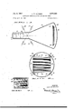
- Figure I is asemi-diagrammaticview of a cathoderay.tube showing'in crossrscct-ion a color;,gridstructure in accordance @with the presentv invention;
- Figure'2 is a plan .viewvofrthe. color grid structure-of Fig. 1; as-scen fromthe, electron, gun end of;the.-cathoderay t be;
- Figure 4- is,a perspective'view ;of Fig.3, showing-in addition one manner of (securing-the base plateassembly ,to; the color grid unit;
- figure 5 is;a;perspectiveview of aport-ion. of --Fig. 3, ,showing in further detail the mannerinxwhich thfiztWO .sets of ,grid conductors are positioned by .the grooved side members;
- Figure. 6 is an end- ,-vi ew of one of the side -members of Figs. 3, 4, and 5, yShOWirigI-h manner in nwhich -arr-ivingwan.d;dep arting -wires ⁇ o f av single turn are eaused' ,tog'bepositioned one; above theother by means ofigrooves ;cut into thesurface of the :side member; and
- Figure .7 isa;plan-view-of a portion of the target. area -of ,Fig. 2, showing one preferred relationship between the 1 grid conductors" and phosphor .strips.
- Fig. 1 a cathode-ray tube certain ;-parts of which .are :coniventional.
- cathode 1,2 which act vas a sour e of ele ron f0r .dev 1 pment ,into a sc n n beam.
- the electron beam 14 is caused to scan a phosphor-coated target, or base plate, 26 to develop light which is visible through the end wall 28 of the envelope 10.
- a substantially rectangular frame 30 adapted to fit within the envelope of the cathode-ray tube 10.
- This frame 30 is made up of a pair of oppositely-disposed -L-sh aped channel members 32, which form two sidesof theframe, and a pair of grooved .side, members 34.which; form the remainingtwo sides, thus defining a central window,.a-rea. 1'Ihe'.,L-shaped members 32 are respectively securedJto the-.side-anembers 34 by rivets ,36, :one of Which is shownin each of Figs. 4 and 5.
- Each side member34' is of generally flat configuration, and maybe fabricated for example, from .062" thick type 430 stainless steel sheet bent double as indicated in the drawing.
- the particular manner of fabricating the frame-30 formsno part of ,the; present invention, and anygindication that it. maybe formed by bending and rivetingroperationsis;merelyrfor the, purpose ,of. explanation.
- Theframe 30 is provided .at :each:v corner .withsa lug vor.tab,38-vv hich is .shown in;Fig..2.;ashavin g. a contour generally similar to the internal .periphery..of .the-envelope .10. ,In thecaseofwa metal-envelopelO, small angles 40 may be welded to the inside surface .ofthe envelope EllizPOSitiOHS .where.it .is desiredtoattachthe lugs 38. .T helugsare joined to the .angles bymeans of. rivetsAZavhich preferably assthmughMceramic.
- bushings .(not shown) which areprovided .with insulating di-scs.on eachend to isolate ,electricallytthe frame 30 from theenvelope 10.
- Other meansof attachment may be employed, especially .when ,glassinstead Ofmetal en- ,velopes are used. l-Iowever, .these .constructional featnres per seformno-partof the. present invention,.and
- A. first continuous. filamentaryconductor. (such as #302 .stainless-steel of.6 milthickness) is wound around the oppositely-disposed frame ,side members 34 in coil-like fashion so as to formtwohsets .of .strands.
- the .above .operation which may be termed the first, or.initial,.winding, is so carried out that the spacing'be- .tween adjacent turns .is substantially twice the spacing desired between adjacent conductors tof the finished, grid assembly.
- grooves are cut into the outer edge of one of the side members 34, with the direction of such grooves being nominally vertical or normal to the plane of the finished grid, but at the same time deviating from this normal condition by an amount necessary to take into account the angle at which the cathoderay scanning beam arrives at the plane of the grid assembly.
- Such grooves are generally indicated by the reference numeral 43 in Fig. 4, and are so cut into the side member 34 that the first winding operation described above results in the continuous filamentary conductor being received in these grooves to thus establish the position of the strands as they cross the open, or window area defined by the frame members. It is intended that the parallel condition of the wires constituting each turn be maintained across the entire window area of the cathode-ray tube.
- Means must also be provided for causing the wire to be shifted laterally'to a new position following the completion of any particular turn and prior to the commencement of a succeeding turn, so that during the latter winding the two strand conductors 44 and 46 thereof will also be substantially parallel to one another and lie directly one above the other as seen by an electron passing adjacent thereto.
- the remaining one of the two side members 34 has grooves cut into its outer edge which are not substantially normal to the plane of the grid assembly (as are the grooves of the first-mentioned member) but instead are caused to have the angular relationship best illustrated in Fig. 6 of the drawings.
- the upper, or arriving, strand conductors 44 which are formed by the first winding operation (or by wire #1 as indicated in this figure) arrive along the upper surface of the side member 34 in the position shown. However, in passing over the outer edge of this side member, they fall within grooves which are cut angularly as indicated in the drawing.
- the wire By the time the wire reaches the lower, or under, surface of the side member, it is offset to the position 46 shown therein.
- This position 46 bears such a relationship to the position 44 that (considered in a plane normal to the plane of the frame member) it is shifted laterally by substantially twice the distance desired between adjacent turns of the finished grid assembly.
- a second winding operation is carried out in an exactly similar manner except that (as best shown in Fig. 6) wire #2 begins at a point midway between two adjacent turns of wire #1.
- This second winding operation produces two further sets of conductors lying intermediate the conductors 44 and 46, and hence these two second sets of conductors are given the designations 44a and 46a (see Figs. 4, 5 and 6).
- Each turn of the second winding operation forms two strand conductors 44a and 46a lying in an essentially vertical plane in the same manner as two corresponding conductors 44 and 46 formed by the first winding operation.
- the finished grid assembly as shown in the drawings, consists of two sets of strands lying intermediate each other (insofar as the spacing between adjacent turns is concerned) and with each turn of each winding operation producing two conductors which lie one above the other as they are viewed by an electron of the scanning beam 14. Consequently, such an electron passing between two adjacent upper strand conductors 44 and 44a will likewise pass between two lower strands 46 and 46a. This will be clear from a consideration of Figs. 3 and 4 of the drawings.
- the backing area, or base plate, 26 carries on one of its surfaces a series of phosphor strips laid down in a manner such as will be described in connection with Fig. 7. That is, the sequence of these phosphor strips may be, for example, red, green, blue, green, red, green, etc.
- the sequence of these phosphor strips may be, for example, red, green, blue, green, red, green, etc.
- wires are associated with each red and blue strip but none with the green.
- the base plate 26 is mounted in a pair of L-shaped support members 48, one of which is shown in each of Figs. 3 and 4.
- the plate 26 is cradled in these support members in the manner shown, the latter being preferably composed of the same material as the frame sections 32 and 34.
- Fig. 7 The relative position of the conducting strands, or grid wires, andthe red, blue and green phosphor strips which are applied to that surface of the base plate 26 impacted by the electron scanning beam 14, is shown in Fig. 7.
- a desirable'pattern has been found to consist of repeating groups of strips in the order red, green, blue, green, red, green, etc.
- the strip widths are chosen in accordance with tube design so as to provide electro-optical rather than physical relationships between the grid wires and the phosphor strips.
- Each adjacent pair of grid wires accordingly is designed to subtend (in an electro-optical sense) a portion of the target electrode surface which includes phosphor areas of each of the component colors.
- the distance between adjacent grid wires is substantially equal in one dimension to a single elemental area of the image to be resolved by the cathode-ray tube.
- an electron of the scanning beam 14 arriving at the grid wire assembly from the main deflecting area of the cathode-ray tube 10 will pass first through one of the apertures formed by a strand conductor 44 and an adjacent strand conductor 44a.
- the electron will be subjected to a micro-deflection in a sidewise, or transverse, direction the magnitude of which depends upon the potentials applied to these conductors 44 and 44a.
- there is an electric field established between these conductors and the electron-in question will be subjected to a'- la'teral' deflectiomdepent'iing upon the number of lines off-force-of this electrostatic-field "cut by the electron during its passage between the two strand conductors.
- the electron After passing'through'this area, the electron continues toward the base plate 2'6, and passes through a secondele'ct'ric field developed 'betweentwo lower conductors 46 and 46a. In passing through this se'cond electrostatic field, the electron cuts a further number of lines of force,and, hence, is subjected to- -a further transverse o'r micro defl'ec'tio'n depending again u'pon the number of field lines cut thereby. These two 'micro deflection' forces when added together, produce: a total deflection of the electron which'is greater than: that produced by'either. field alone.
- a still further advantage to be realized by employing the concept set forth in the present application is that the tendency of the individualstrand conductors of the grid to vibrate due to rapid changes in the value of the color switching potentials is very materially reduced as the magnitude of these 'deflection'potentials is lowered.
- the importance of inhibiting grid wire vibration is brought out in a copending United States patent application. of Howard R. Patterson, Serial No. 364,778, filed June 29, 19.53, and assigned to the same assignee as the present application. In this Patterson application, it is brought out that unrestricted vibration of the grid wires, in many cases, produces such severe color contamination in. the reproduced image as to make the latter commercially unacceptable.
- the vibrational elfects of the grid assembly are much less severe, and in some cases it may even be possible to omit the various damping devices which previously had been mandatory in grid wire construction of the present type.
- a still further benefit obtained from the use of a grid assembly constructedzin accordance with the present invention is'that stars or random spots of intense illumir nation developed on the phosphor-coated target, are reduced both in number and'severity due to the decreased electron emission from the grid wireswhen lower deflecting voltages are employed.
- a grid structure wound in continuous fashion doesnot possess many ofthe properties inherent in gridstructures fabricated by back-and-forth wind ing techniques, such-as-the problem of the wires adhering to the hooks around which they pass.v
- one of the principal advantages of the present invention resides in a lowering of the power requirementsfor micro-deflection of a cathode-ray beam, in a tube of the nature described above, by causing the scanning beam electrons to pass sequentially through two-electrostatic fields each of which produces a lateral deflection of the cathode-ray beam for color-changing purposes.
- the two fields acting together may crcatea condition in which an electron passing therethrough cuts double the number of lines of force which it would'cut in passage through-one of the .two field's alone. Consequently, its lateral deflection may be double that of a single field.
- each of the two fields of this'di sclosure' maybe so developed that the number of linesof' force out by an electron is substa'ntiallyequalto thatof'a single grid. This) requires but half as r'nuch voltage on the conductors and consequently les's deflecting power.
- l-. Ina grid structure designed for incorporation into'a cathode-ray tube having a phosphor-coated target electrode on'which images are reconstituted in a plurality of colors: the combination of a frame having two pairsof oppositely dispos'ed members together defining a Window area thereb'etween, one member of one of the said pairs being'provided with aseries of parallel grooves onits outer edge, thedirection of said grooves being essentially normal to the :plane of said frame, the other member of saidone pair also being provided with a series of parallelgrooves on its outer edge, the direction of said last-men'- tionedJgrooves being other than essentially normal to the plane'of said frame; a.
- first continuous conductor wound in coil-like fashion around said frame and electrically insulatedtherefromwith successive turns of said'co'il lying within alternate grooves in each of said one pair of frame members; and a second continuous conductor also wound in coil-like fashionaround said frame and electrically insulatedtherefrom with successive turnsof said coil lying within the alternate grooves in each of said one pair of frame members not occupied by said first conductor, thereby to formtwosets of interleaved parallel strands across the Window of said frame respectively lying in planes which are separate yetparallel to one another, with each completeturn of both saidfirst conductor and said second conductor consisting of two strands defining a plane which is substantially parallel to the trajectory of an electron developed Within said cathode-ray tube and directed to that area of the said target electrode proximate to the said two strands.
- a grid structure designedfor incorporation into a cathode-ray tube in which an electron scanning beam is developed and then deflected so as to scan a phosphorcoated-target thereby to reconstitute images in a plurality of colors
- said grid structure including a pair'of continuous electrical conductorswound in coil-like fashion so that each turn of each'conductor consists of two strands lying in a plane substantially parallel to the trajectory of an electron developed by said cathode-ray tube and direct'ed t'o that'p'ortion of said target adjacent said' two strands, such that the latter are passed sequentially by said electron in its journey to said target, and means for electrically insulating one of said pair of conductors from the other so that diiferent electrical potentials may'b'e'applied thereto while maintaining allp'ortions of each individual conductor in a substantially unipotential condition.
- a second continuous conductor also wound in essentially coil-like fashion around'said frame sothatthetu'rns formed by said-second conductor are interleaved with the turnsfo'rmed by said first conductorand are electrically insulated therefrom, eaclilturnformed by said secondconducto'r also consisting of two strands each of which lies substantially equi distantly-'throughoiit' its length from thephosphor-coated 9 surface of said target electrode, and with the two lastmentioned strands also defining a plane essentially parallel to the path of an electron of said scanning beam passing adjacent to said strands toward said target electrode such that the electron in following this path will pass by the two said strands in sequence.
- a grid structure adapted for positioning substantially adjacent to a target upon which is a coating of a plurality of different phosphors arranged in strip formation in a repeating cycle and which strips are adapted to become luminous in different colors under electron beam impact, which comprises a first plurality of generally uniformly spaced linear conductors supported in substantially parallel relationship to each other along a surface adapted to be located adjacent to the target and within the cathode-ray tube to extend within the electron beam path to the target substantially parallel to the strips of the target, a second plurality of linear conductors extending parallel to the linear conductors of the first set and spaced from each other by substantially the spacings of the con ductors of the first set and uniformly spaced from the conductors of the first set, the linear conductors of the second set being adjacent to those of the first set and adapted to be held closer to the electron beam source than the linear conductors of the first set, means to connect electrically alternate linear conductors of each set to
- a grid structure for a cathode-ray tube comprising a pair of parallelly positioned support elements spaced by substantially one dimension of a raster to be traced upon the tube target, a plurality of parallelly tautly strung conductors stretched between the supports, one part of the conductors being stretched between the supports to lie at one side thereof in a surface defined by the support and the other part of the conductors being stretched between the supports to lie at the other side thereof with each conductor of each set equally spaced from the space-related conductor of the other set, means to connect electrically alternate linear conductors of each set to maintain the connected conductors at like potential and so as to connect adjacent conductors to permit the application of different relative potentials thereto, and means to connect the conductors of the two sets electrically in parallel.
- a grid structure adapted for positioning substantially adjacent to a target having thereon coatings of material adapted to luminesce in selected color light under electron beam impact according to a repeating pattern of strips arranged in a cycle of an additive color series which comprises a pair of supports separated from each other by a distance at least as great as one dimension of a raster to be traced in the target, a first conductor 10 strung back and forth between and around each of the supports and in a continuous strand pattern extending lengthwise of the support with each adjacent strand substantially uniformly spaced and each adapted to extend parallel to the target strips and of which the portion spanning the distance between the supports on one side thereof is uniformly spaced from the portion spanning the distance between the supports on the other side thereof, a second conductor similarly strung between the supports with each conducting strand spanning the distance between the supports being positioned intermediate a corresponding strand of the first conductor, means electrically to insulate the conductors of each set and means to apply potentials to each. conductor so that at
- a grid structure adapted for positioning adjacent to the target for color switching control which comprises a first plurality of generally uniformly spaced linear conductors in parallel relationship to each other supported along a surface adapted to locate adjacent to the target and in the cathode-ray beam path to the target with.
- a second plurality of uniformly spaced linear conductors also in parallel relationship to each other and extending parallel to the linear conductors of the first set and spaced from each other by substantially the spacings of the conductors of the first set and uniformly spaced from the conductors of the first set, the linear conductors of the second set being located adjacent to those of the first set and in such relation thereto as to be closer to the electron beam source and more remote from the target than the linear conductors of the first set, means to connect electrically alternate linear conductors of each set to maintain the connected conductors at like potential and so as to connect adjacent conductors to permit the application of different relative potentials thereto and means to connect the conductors of the two sets electrically in parallel.
Landscapes
- Engineering & Computer Science (AREA)
- Multimedia (AREA)
- Signal Processing (AREA)
- Cathode-Ray Tubes And Fluorescent Screens For Display (AREA)
Description
ELECTRODE CONSTRUCTION FOR CATHODE-RAY TUBES Filed April 19. 1954 L. W. ALVAREZ Jan. 8, 1957 2 Sheets-Sheet l EIIE IISIIHHIK IHIHI [Hill I IIHHIIHHIIHI \HIHIIHHIHH Hllll I HIIIHIHHIIIII INVENTOR. Lu/s h./ fl/uaraz Jan. 8, 1957 w. ALVAREZ 2,777,083
ELECTRODE CONSTRUCTION FOR CATHODE-RAY TUBES Filed April 19; 1954 2 Sheets-Sheet 2 ;z 44 34 .f 0 K a}- z/// A EIJE| 3 3/4/7} IN V EN TOR. W 2 Luis M flll a/"ez EII5- E BY United tes ELECTRGDE CONSTRUCTIGN FOR CATHODE- RAY TUBES Luis W. Alvarez, Berkeley, Calif., assignor to Chromatic Television Laboratories, Inc, New York, N. Y., a corporation of California Application April 19, 1954, Serial No. 423,935
7 Claims. (Cl. 313-78) cent to a striped phosphor screen. A grid of this nature may serve as one component of an electron lens system to focus the beam electrons into a pattern of thin lines registered with the phosphor strips of the screen, and,
by the application of proper switching potentials to the linear conductors of the grid, a selective nucro deflection of the beam onto the various phosphor areas may be brought about and hence the reproduction of a polychrome image.
One form which these linear conductors may take is that of a series of strips of sheet metal mounted parallel to one another in the dimension extending across the target area and lying in planes substantially parallel to the paths of electrons from the gun to the phosphor coated tar-get proper. Adjacent strips are mutually insulated from one another, and alternate strips are connected together to respective output terminals. The elements of this strip assembly are so arranged that the struc ture as a whole is at a substantially uniform distance from the surface of the target area. The latter is coated with a conductive film having electron permeable characteristics, so that, when suitable potentials are applied thereto and to the strips of the electrode structure, these elements will together constitute an electron lens which has a converging effect upon .the electrons of the scanning beam which pass between adjacent plates. This convergence may be to a line focus on the target surface.
Alternatively, instead of plates, linear conductors as wires may be employed. All of these linear conductors are intended to lie in .a single plane close to the sur face of the target electrode.
The above effect will be more clearly understood when the action of the electrostatic field in the region of the conductors on an electron passing between adjacent conductors is considered. The lines of force which comprise this electrostatic field set upon the electrons in the scanning beams in such a manner that any particular electron passing through the space between two adjacent strand conductors (unless it passes through the exact center of the space between these conductors and normal to the plane thereof) is directed away from the nearest conductor by the lateral component of this electrostatic field. Expressed ditferently, an electron passing perpendicularly through the exact center of the space between adjacent conductors will cross or cut none of the lines of force, and therefore will hold to its original p-ath. An electron passing very close to either conductor Patented Jan. 8, 1957 will cut a major portion of the field lines term 'mating on that conductor, and therefore will be repelled from the latter by a relatively large lateral force. It may thus be said that all of the electrons in the scanning beam which pass between any two adjacent conductors are subjected to lateral forces which are at least approximately proportional to their distance from the axis of the individual lens defined by the conductors in question, so that there is a resultant convergence of the beam electrons toward a single line upon the phosphor-coated target surface.
As brought out above, adjacent conductors of the electrode assembly are mutually insulated and alternate strips or conductors are connected together. If now a difference of potential is applied between these two sets of conductors, a deflection field is created such that all of the electrons in the beam passing through the interspace between the conductors will be given equal accelerations away from the conductor which is negative toward the one which is positive. The result is a shifting of focus toward whichever of the conductors happens to be positive at the moment. In adjacent elementary lenses, therefore, the deflection occurs in opposite directions.
In the case of deflection of the beam at a field-sequential rate, the colon-control voltage used will preferably be of substantially rectangular wave form of a frequency equal to one-third the field frequency, the wave form having a positive potential for the first one-third of the cycle, zero for the next onethird, and negative for the last one-third of the cycle. With a line-sequential systern, the wave form might be substantially the same but at one-third line instead of one-third field frequency. The dot-sequential system, or one in which colors are displayed at socalled element frequency, could still use the same wave form at a corresponding higher frequency, or this wave form could be that of a sine WIZJVS which would display green twice per cycle fora short period, and red and blue once per cycle for a longer period. As a still further example, this sine wave could be broken up into display periods spaced 60 electrical degrees apart.
When the phosphor-coated target is covered with an electron-permeable layer of conductive material, and when this electron-permeable layer has a potential applied thereto which is considerably higher than the average, or mean, potential of the deflecting electrode, then very little power will be required to cause a deflection of the cathode-ray beam back-and-forth between various colored phosphor areas of the screen in the manner above described. It will also be recognized that the frequency of color change has a very material effect upon the power requirements, the latter being very much higher for color change produced at so-called element frequency than it is for either lineor field-sequential color change.
In any grid structure constructed in accordance with the above, it is fundamental that the lateral velocity imparted to electrons passing between adjacent conductors, is proportional to the number'of lines of force they cross or out. It is also fundamental that the number of lines of force produced in the space between adjacent conductors is proportional to the high frequency alternating current which charges and discharges the conductors to create the electronic field. Since the power requirement of the structure are directly proportional to the voltage multiplied by this charging current divided by the circuit efficiency factor Q, it will be seen that a reduction in the required power may be brought about if some way can be found of opera-ting the tube with a lower voltage on the grid conductors without decreasing deflection field strength. This the present invention is designed to accomplish.
In accordance with a principal feature of this disclosure .thapwe .tequ rement in .aeathoderay tube of the nature described above are materially reduced by lowering the voltage applied to the strand conductors .o he gri s ructure i 'a rd rl t t-prod a micr ;d qn of h sca in :be m- -.I a m.u h .1 th PP varies in direct :preportion to ,-the-,;applied-v.oltage,-.and inasmuch,as'theqlatter isinversely proportionaito the capacity between;adjaeent. -elementsof t-he;., grid, this, capacity :is raised -.by;ut,-i lizing.1w sets-of: linean conductors instead :of one set; lying-onebehind; the other along-the e t o m t t the nhesp en arg r Qne. object of the present ,---invention, therefore, is to -provide a grid structure of the,- above natureor; imagereproducing cathode-ray tubes designed to,reeonstitute images in ..p olychrome.
,A further: object of;thepresent inventionis to reduce the power required for .micro-defleetion in .a cathoderay tube of -the,.above;type.
A.. still further. objecteof the;p res,ent invention is -:to Pr v d a r ath -ray t be d s gned t rspo y hr me image vreproduction and incorporating a grid structure positioned adjacent toa striped phosphoriscreen, in which the powerrequired by.this--grid structure formicro-de- -ilection of the cathode-ray beam-.is materiallymeduced over structures previously (employed.
Otherobjects,,andadvantages of the presentinvention will be apparent from the following description and from .therdrawings, in which:
Figure I is asemi-diagrammaticview of a cathoderay.tube showing'in crossrscct-ion a color;,gridstructure in accordance @with the presentv invention;
Figure'2 is a plan .viewvofrthe. color grid structure-of Fig. 1; as-scen fromthe, electron, gun end of;the.-cathoderay t be;
Figure v3 isia detailedview eta-portion of-Fig. 2;
,Figure 4-is,a perspective'view ;of Fig.3, showing-in addition one manner of (securing-the base plateassembly ,to; the color grid unit;
figure 5 .is;a;perspectiveview of aport-ion. of --Fig. 3, ,showing in further detail the mannerinxwhich thfiztWO .sets of ,grid conductors are positioned by .the grooved side members;
Figure. 6 is an end- ,-vi ew of one of the side -members of Figs. 3, 4, and 5, yShOWirigI-h manner in nwhich -arr-ivingwan.d;dep arting -wires\ o f av single turn are eaused' ,tog'bepositioned one; above theother by means ofigrooves ;cut into thesurface of the :side member; and
Figure .7 ,isa;plan-view-of a portion of the target. area -of ,Fig. 2, showing one preferred relationship between the 1 grid conductors" and phosphor .strips.
Referring now.to;the-;drawing, there isshown in Fig. 1 a cathode-ray tube certain ;-parts of which .are :coniventional. For example, in the :neck end of :the en- \velope it) there is an indirectlyrheated cathode 1,2 which act vas a sour e of ele ron f0r .dev 1 pment ,into a sc n n beam. the l r 111' indic e rseh mtica ly vih rac At ia en tton na-rti lly;. u ounding :the thod 1 2 1 cen ro ..-g-tt elre ele r e 161 .ahly apertured 1, to permit @the passage ;of ;electrons which are subsequently for-med into the .beam :14. Ihe c n- -trol grid .16 functions in ,the usual manner zto -m0d u- .late the emittedstream ofaelectrons in accordance with tl1e potential applied ;thereto relativeztolthe eathode 12. .Alsoin the-.neck-;end\of the:tubeithereiis provided agrid #2 or first anode tidentified by :Ecferencemumeral .118) .to which .suitable potentials l-may vb .flhp ied $80 as to -result in aninitial acceleration-of the;electrons ernitted zfrom thercathode d2. -Adjacentitoithe grid:,#;3 there is ;-p,os-itioned a grid or second anode ,Qreference numeral 20) for supplying an ,additional acceleration to theelectron.
:D,fi g w t t mnr sin a horiz Pa. r s22 .andva vertical pair-. ZZQ- are provided for ;tl 1 e usual scanning purposes. Obviously, the terms horizontal ;and
--fvertic-al .are used herein in ;a descriptive. :tsen-se :only.
'4 Thus, the electron beam 14 is caused to scan a phosphor-coated target, or base plate, 26 to develop light which is visible through the end wall 28 of the envelope 10.
Best shown in Fig. 2 is a substantially rectangular frame 30 adapted to fit within the envelope of the cathode-ray tube 10. This frame 30 is made up of a pair of oppositely-disposed -L-sh aped channel members 32, which form two sidesof theframe, and a pair of grooved .side, members 34.which; form the remainingtwo sides, thus defining a central window,.a-rea. 1'Ihe'.,L-shaped members 32 are respectively securedJto the-.side-anembers 34 by rivets ,36, :one of Which is shownin each of Figs. 4 and 5. Each side member34'is of generally flat configuration, and maybe fabricated for example, from .062" thick type 430 stainless steel sheet bent double as indicated in the drawing. However, the particular manner of fabricating the frame-30 formsno part of ,the; present invention, and anygindication that it. maybe formed by bending and rivetingroperationsis;merelyrfor the, purpose ,of. explanation.
.Theframe 30 is provided .at :each:v corner .withsa lug vor.tab,38-vv hich is .shown in;Fig..2.;ashavin g. a contour generally similar to the internal .periphery..of .the-envelope .10. ,In thecaseofwa metal-envelopelO, small angles 40 may be welded to the inside surface .ofthe envelope EllizPOSitiOHS .where.it .is desiredtoattachthe lugs 38. .T helugsare joined to the .angles bymeans of. rivetsAZavhich preferably assthmughMceramic. bushings .(not shown) which areprovided .with insulating di-scs.on eachend to isolate ,electricallytthe frame 30 from theenvelope 10. Other meansof attachment may be employed, especially .when ,glassinstead Ofmetal en- ,velopes are used. l-Iowever, .these .constructional featnres per seformno-partof the. present invention,.and
furtherrnoreareof the samegeneralnature ,asalready' in use in the art, so that no further details in regard thereto vwill beset forth herein.
A. first continuous. filamentaryconductor. (such as #302 .stainless-steel of.6 milthickness) is wound around the oppositely-disposed frame ,side members 34 in coil-like fashion so as to formtwohsets .of .strands. One such set of strands (indieatedin the drawingby.the reference numeral 44) .is.comp.osed of those Which1passalong the upper surface. of each grooved, side member 34 .(as .best showniniFig. 5) .and the. o.t,her=set.of strands :(idmtified as .46) is.c0mp0sed;of those passing along the under surface;of the side member. .It will be apparent from aconsideration of the drawings, ,and especially Figs. 3, -.4 and 5,.thatthese two sets of strand conductors-lie in separateplanes one above the other, the distance be- ,tweenthe planes being determined by the thickness of vthe frame member.3f4.
The .above .operation, which may be termed the first, or.initial,.winding, is so carried out that the spacing'be- .tween adjacent turns .is substantially twice the spacing desired between adjacent conductors tof the finished, grid assembly. Eurthermore, ,since eachiturn of theifir'st winding operation consists of an arriving, .oriuppenstrand .44 ,and a .departing, or .lower, :strand '46, these-two strands whichconstitute-a singleturn are intended .to lie in a :plane which .is .nominally .vertical, .or normal, .torthe surface ofthe ,base plate .26, but at=the same.,time.departs from this normal state by varying .amounts fromcne --section-of-the finished gridassembly to theother depend- -ingtupon-the angle of .lIlGidGHCBgOf the. electron beam. as it arrives at such po-int from the electrongunend:ofithe ,cathode-ray :tube. Expressed differently, theaplane .in which these -,two strand conductors of a ,single turn; lie is substantially;paralleltothe path ofascanning-heamelectron the trajectory of'whiehilies inaor adjacent lZO'athiS pla e. ,Hence,,in1a;general-.sense, itimay besaid that this :plane (whi h includes the 1two-,strand. conductors making ;up :a; single turn of thersO-Qfllldififst (winding) als o,in-
:cludes'the gcenter .of deflection pf thetcathodeqray beam.
In order to insure that each of the strand conductors 44 and 46 which together constitute a single turn of the first winding lie in such a plane, grooves are cut into the outer edge of one of the side members 34, with the direction of such grooves being nominally vertical or normal to the plane of the finished grid, but at the same time deviating from this normal condition by an amount necessary to take into account the angle at which the cathoderay scanning beam arrives at the plane of the grid assembly. Such grooves are generally indicated by the reference numeral 43 in Fig. 4, and are so cut into the side member 34 that the first winding operation described above results in the continuous filamentary conductor being received in these grooves to thus establish the position of the strands as they cross the open, or window area defined by the frame members. It is intended that the parallel condition of the wires constituting each turn be maintained across the entire window area of the cathode-ray tube.
Means must also be provided for causing the wire to be shifted laterally'to a new position following the completion of any particular turn and prior to the commencement of a succeeding turn, so that during the latter winding the two strand conductors 44 and 46 thereof will also be substantially parallel to one another and lie directly one above the other as seen by an electron passing adjacent thereto. To produce this offset condition of successive turns of the so-called first winding operation, the remaining one of the two side members 34 has grooves cut into its outer edge which are not substantially normal to the plane of the grid assembly (as are the grooves of the first-mentioned member) but instead are caused to have the angular relationship best illustrated in Fig. 6 of the drawings.
As shown in this figure, the upper, or arriving, strand conductors 44 which are formed by the first winding operation (or by wire # 1 as indicated in this figure) arrive along the upper surface of the side member 34 in the position shown. However, in passing over the outer edge of this side member, they fall within grooves which are cut angularly as indicated in the drawing. By the time the wire reaches the lower, or under, surface of the side member, it is offset to the position 46 shown therein. This position 46 bears such a relationship to the position 44 that (considered in a plane normal to the plane of the frame member) it is shifted laterally by substantially twice the distance desired between adjacent turns of the finished grid assembly.
Following the first winding operation set forth above, a second winding operation is carried out in an exactly similar manner except that (as best shown in Fig. 6) wire #2 begins at a point midway between two adjacent turns of wire # 1. This second winding operation produces two further sets of conductors lying intermediate the conductors 44 and 46, and hence these two second sets of conductors are given the designations 44a and 46a (see Figs. 4, 5 and 6). Each turn of the second winding operation forms two strand conductors 44a and 46a lying in an essentially vertical plane in the same manner as two corresponding conductors 44 and 46 formed by the first winding operation. Thus, the finished grid assembly, as shown in the drawings, consists of two sets of strands lying intermediate each other (insofar as the spacing between adjacent turns is concerned) and with each turn of each winding operation producing two conductors which lie one above the other as they are viewed by an electron of the scanning beam 14. Consequently, such an electron passing between two adjacent upper strand conductors 44 and 44a will likewise pass between two lower strands 46 and 46a. This will be clear from a consideration of Figs. 3 and 4 of the drawings.
Since different potentials are intended to be applied to the two sets of strand conductors respectively formed by the two winding operations (or, in other words, wires # 1 and #2 as indicated in Fig. 6) means are provided for insulating these two sets of conductors both from each other and from the electrically-conductive side members 34 which form part of the frame 30. One preferred means of accomplishing this result is by coating the entire frame 30 (or, alternatively, coating only the grooved side members 34) with a suitable insulating substance. This coating may be applied by spraying the frame with thermo-setting enamel or liquid porcelain, for example, prior to the above-mentioned winding operations. This will result in a thin film of insulation being formed over that portion of the surface of the frame contacted by the strand conductors of the grid assembly.
The backing area, or base plate, 26 carries on one of its surfaces a series of phosphor strips laid down in a manner such as will be described in connection with Fig. 7. That is, the sequence of these phosphor strips may be, for example, red, green, blue, green, red, green, etc. For satisfactory operation of the tube being described, it is necessary that each of the strand conductors be properly positioned with respect to these phosphor strips. That is, wires are associated with each red and blue strip but none with the green.
The base plate 26 is mounted in a pair of L-shaped support members 48, one of which is shown in each of Figs. 3 and 4. The plate 26 is cradled in these support members in the manner shown, the latter being preferably composed of the same material as the frame sections 32 and 34.
There have now been described two units, or sub-assemblies, one of which may be designated as the grid wire sub-assembly, as shown in Fig. 5, for example, and the remaining one constituting the base plate sub-assembly, which includes the phosphor-coated plate 26 and the two support members 48. These two sub-assemblies are now brought into position as best shown in Fig. 4, and, in this position, the two units are secured together by means of the angles 50 (one of which is shown in Fig. 4). The rivet 36, which joins one of the L-shaped channel members 32 to one of the grooved side members 34, may also pass through this angle 50, as best shown in Fig. 4, while another rivet 52 secures the angle 50 to the base plate support member 48. Obviously, four such securing means are employed, one on each corner of the frame 30.
The relative position of the conducting strands, or grid wires, andthe red, blue and green phosphor strips which are applied to that surface of the base plate 26 impacted by the electron scanning beam 14, is shown in Fig. 7. Although the particular arrangement of the phosphor strips forms no part of the present invention, nevertheless a desirable'pattern has been found to consist of repeating groups of strips in the order red, green, blue, green, red, green, etc. The strip widths are chosen in accordance with tube design so as to provide electro-optical rather than physical relationships between the grid wires and the phosphor strips. Each adjacent pair of grid wires accordingly is designed to subtend (in an electro-optical sense) a portion of the target electrode surface which includes phosphor areas of each of the component colors. Generally speaking, however, it may be said that the distance between adjacent grid wires is substantially equal in one dimension to a single elemental area of the image to be resolved by the cathode-ray tube.
It will now be appreciated that an electron of the scanning beam 14 arriving at the grid wire assembly from the main deflecting area of the cathode-ray tube 10 will pass first through one of the apertures formed by a strand conductor 44 and an adjacent strand conductor 44a. As such, the electron will be subjected to a micro-deflection in a sidewise, or transverse, direction the magnitude of which depends upon the potentials applied to these conductors 44 and 44a. Expressed differently, there is an electric field established between these conductors and the electron-in question will be subjected to a'- la'teral' deflectiomdepent'iing upon the number of lines off-force-of this electrostatic-field "cut by the electron during its passage between the two strand conductors. After passing'through'this area, the electron continues toward the base plate 2'6, and passes through a secondele'ct'ric field developed 'betweentwo lower conductors 46 and 46a. In passing through this se'cond electrostatic field, the electron cuts a further number of lines of force,and, hence, is subjected to- -a further transverse o'r micro defl'ec'tio'n depending again u'pon the number of field lines cut thereby. These two 'micro deflection' forces when added together, produce: a total deflection of the electron which'is greater than: that produced by'either. field alone.
Instead of producing a greater overall deflectiont ofthe electron beam, it will be recognizedthat a deflection may be obtained whichise'qual torthatproduced by the electro static field developed between al single 'set'of conductors through-the expedient of causing each of the two fields to produce approximately half the total desired deflection; The voltage required for producing such a total deflection by these'two individual fieldsacting in sequence-may be only half of the voltage required to produce the same deflection by a single field, inasmuch as the capacity factor ofthe grid assembly hasbeen doubled.
A still further advantage to be realized by employing the concept set forth in the present application is that the tendency of the individualstrand conductors of the grid to vibrate due to rapid changes in the value of the color switching potentials is very materially reduced as the magnitude of these 'deflection'potentials is lowered. The importance of inhibiting grid wire vibration is brought out in a copending United States patent application. of Howard R. Patterson, Serial No. 364,778, filed June 29, 19.53, and assigned to the same assignee as the present application. In this Patterson application, it is brought out that unrestricted vibration of the grid wires, in many cases, produces such severe color contamination in. the reproduced image as to make the latter commercially unacceptable. By producing the same degree of microdeflection of the cathode-ray beam with reduced deflection potentials, as is accomplished by use of the concept disclosedherein, the vibrational elfects of the grid assembly are much less severe, and in some cases it may even be possible to omit the various damping devices which previously had been mandatory in grid wire construction of the present type.
A still further benefit obtained from the use of a grid assembly constructedzin accordance with the present invention is'that stars or random spots of intense illumir nation developed on the phosphor-coated target, are reduced both in number and'severity due to the decreased electron emission from the grid wireswhen lower deflecting voltages are employed. Still further, a grid structure wound in continuous fashion (as in the one set forth herein) doesnot possess many ofthe properties inherent in gridstructures fabricated by back-and-forth wind ing techniques, such-as-the problem of the wires adhering to the hooks around which they pass.v
In summary, therefore, it may be said that one of the principal advantages of the present invention resides in a lowering of the power requirementsfor micro-deflection of a cathode-ray beam, in a tube of the nature described above, by causing the scanning beam electrons to pass sequentially through two-electrostatic fields each of which produces a lateral deflection of the cathode-ray beam for color-changing purposes. The two fields acting together may crcatea condition in which an electron passing therethrough cuts double the number of lines of force which it would'cut in passage through-one of the .two field's alone. Consequently, its lateral deflection may be double that of a single field. For thesameamount of deflection, each of the two fields of this'di sclosure' maybe so developed that the number of linesof' force out by an electron is substa'ntiallyequalto thatof'a single grid. This) requires but half as r'nuch voltage on the conductors and consequently les's deflecting power.
Having thus-described the invention, what is claimed is:
l-. =Ina grid structure designed for incorporation into'a cathode-ray tube having a phosphor-coated target electrode on'which images are reconstituted in a plurality of colors: the combination of a frame having two pairsof oppositely dispos'ed members together defining a Window area thereb'etween, one member of one of the said pairs being'provided with aseries of parallel grooves onits outer edge, thedirection of said grooves being essentially normal to the :plane of said frame, the other member of saidone pair also being provided with a series of parallelgrooves on its outer edge, the direction of said last-men'- tionedJgrooves being other than essentially normal to the plane'of said frame; a. first continuous conductor wound in coil-like fashion around said frame and electrically insulatedtherefromwith successive turns of said'co'il lying within alternate grooves in each of said one pair of frame members; and a second continuous conductor also wound in coil-like fashionaround said frame and electrically insulatedtherefrom with successive turnsof said coil lying within the alternate grooves in each of said one pair of frame members not occupied by said first conductor, thereby to formtwosets of interleaved parallel strands across the Window of said frame respectively lying in planes which are separate yetparallel to one another, with each completeturn of both saidfirst conductor and said second conductor consisting of two strands defining a plane which is substantially parallel to the trajectory of an electron developed Within said cathode-ray tube and directed to that area of the said target electrode proximate to the said two strands.
2 In a grid structure designedfor incorporation into a cathode-ray tube in which an electron scanning beam is developed and then deflected so as to scan a phosphorcoated-target thereby to reconstitute images in a plurality of colors, the combination of a grid structure positioned adjacent to said target and in the path of the said scanning beam,- said grid structure including a pair'of continuous electrical conductorswound in coil-like fashion so that each turn of each'conductor consists of two strands lying in a plane substantially parallel to the trajectory of an electron developed by said cathode-ray tube and direct'ed t'o that'p'ortion of said target adjacent said' two strands, such that the latter are passed sequentially by said electron in its journey to said target, and means for electrically insulating one of said pair of conductors from the other so that diiferent electrical potentials may'b'e'applied thereto while maintaining allp'ortions of each individual conductor in a substantially unipotential condition.
3. In a grid structure designed for incorporation into a cathode-'raytube'having a phosphor-coated target electrode which the electron scanning beam of said tube is caused to impinge thereby to reconstitute images in a plurality of colors, the-combination of a substantially'rec tangular frame; a first continuous conductor wound in essentially coil-like fashion around oppositely-disposed portions of said frame so'that each turn of saidcoil-like winding consists of two'st'rands each of which lies substantially" equidistantly throughout its length from the phosphor-coated surface of said target electrode; and with the two said strands defining a plane essentially parallel-'to th'e' path of' an electronof said scanning beam passing adjacent to said strands-toward said targetelee trode, whereby the. electron in following this path" will pass'th'e' two said-strands in sequence, a second continuous conductor also wound in essentially coil-like fashion around'said frame sothatthetu'rns formed by said-second conductor are interleaved with the turnsfo'rmed by said first conductorand are electrically insulated therefrom, eaclilturnformed by said secondconducto'r also consisting of two strands each of which lies substantially equi distantly-'throughoiit' its length from thephosphor-coated 9 surface of said target electrode, and with the two lastmentioned strands also defining a plane essentially parallel to the path of an electron of said scanning beam passing adjacent to said strands toward said target electrode such that the electron in following this path will pass by the two said strands in sequence.
4. In a cathode-ray tube for color television, a grid structure adapted for positioning substantially adjacent to a target upon which is a coating of a plurality of different phosphors arranged in strip formation in a repeating cycle and which strips are adapted to become luminous in different colors under electron beam impact, which comprises a first plurality of generally uniformly spaced linear conductors supported in substantially parallel relationship to each other along a surface adapted to be located adjacent to the target and within the cathode-ray tube to extend within the electron beam path to the target substantially parallel to the strips of the target, a second plurality of linear conductors extending parallel to the linear conductors of the first set and spaced from each other by substantially the spacings of the con ductors of the first set and uniformly spaced from the conductors of the first set, the linear conductors of the second set being adjacent to those of the first set and adapted to be held closer to the electron beam source than the linear conductors of the first set, means to connect electrically alternate linear conductors of each set to maintain the connected conductors at like potential and so as to connect adjacent conductors to permit the application of different relative potentials thereto, and means to connect the conductors of the two sets electrically in parallel.
5. A grid structure for a cathode-ray tube comprising a pair of parallelly positioned support elements spaced by substantially one dimension of a raster to be traced upon the tube target, a plurality of parallelly tautly strung conductors stretched between the supports, one part of the conductors being stretched between the supports to lie at one side thereof in a surface defined by the support and the other part of the conductors being stretched between the supports to lie at the other side thereof with each conductor of each set equally spaced from the space-related conductor of the other set, means to connect electrically alternate linear conductors of each set to maintain the connected conductors at like potential and so as to connect adjacent conductors to permit the application of different relative potentials thereto, and means to connect the conductors of the two sets electrically in parallel.
6. In color television apparatus, a grid structure adapted for positioning substantially adjacent to a target having thereon coatings of material adapted to luminesce in selected color light under electron beam impact according to a repeating pattern of strips arranged in a cycle of an additive color series which comprises a pair of supports separated from each other by a distance at least as great as one dimension of a raster to be traced in the target, a first conductor 10 strung back and forth between and around each of the supports and in a continuous strand pattern extending lengthwise of the support with each adjacent strand substantially uniformly spaced and each adapted to extend parallel to the target strips and of which the portion spanning the distance between the supports on one side thereof is uniformly spaced from the portion spanning the distance between the supports on the other side thereof, a second conductor similarly strung between the supports with each conducting strand spanning the distance between the supports being positioned intermediate a corresponding strand of the first conductor, means electrically to insulate the conductors of each set and means to apply potentials to each. conductor so that at either side of the supports a grid structure is provided wherein alternate conductors are maintained at like potential and adjacent conductors may be maintained at relative potentials in accordance with the supplied potentials.
7. In a cathode-ray tube for color television, having a target formed as a coating of a plurality of difierent light producing phosphors arranged in strip formation in a repeating cycle and adapted to become luminous under electron beam impact to develop light in colors additive to produce white light, a grid structure adapted for positioning adjacent to the target for color switching control which comprises a first plurality of generally uniformly spaced linear conductors in parallel relationship to each other supported along a surface adapted to locate adjacent to the target and in the cathode-ray beam path to the target with. the conductors extending parallel to the strips of the target, a second plurality of uniformly spaced linear conductors also in parallel relationship to each other and extending parallel to the linear conductors of the first set and spaced from each other by substantially the spacings of the conductors of the first set and uniformly spaced from the conductors of the first set, the linear conductors of the second set being located adjacent to those of the first set and in such relation thereto as to be closer to the electron beam source and more remote from the target than the linear conductors of the first set, means to connect electrically alternate linear conductors of each set to maintain the connected conductors at like potential and so as to connect adjacent conductors to permit the application of different relative potentials thereto and means to connect the conductors of the two sets electrically in parallel.
References Cited in the file of this patent UNITED STATES PATENTS Re. 23,672 Okolicsanyi June 23, 1953 1,565,708 Bullimore Dec. 15, 1925 1,980,341 Kayko et a1. Nov. 13, 1934 2,067,825 Bullimore Ian. 12, 1937 2,660,684 Parker Nov. 24, 1953
Priority Applications (3)
| Application Number | Priority Date | Filing Date | Title |
|---|---|---|---|
| NL196563D NL196563A (en) | 1954-04-19 | ||
| US423935A US2777083A (en) | 1954-04-19 | 1954-04-19 | Electrode construction for cathoderay tubes |
| GB9878/55A GB784167A (en) | 1954-04-19 | 1955-04-05 | Improvements in or relating to electrode construction for cathode-ray tubes |
Applications Claiming Priority (1)
| Application Number | Priority Date | Filing Date | Title |
|---|---|---|---|
| US423935A US2777083A (en) | 1954-04-19 | 1954-04-19 | Electrode construction for cathoderay tubes |
Publications (1)
| Publication Number | Publication Date |
|---|---|
| US2777083A true US2777083A (en) | 1957-01-08 |
Family
ID=23680776
Family Applications (1)
| Application Number | Title | Priority Date | Filing Date |
|---|---|---|---|
| US423935A Expired - Lifetime US2777083A (en) | 1954-04-19 | 1954-04-19 | Electrode construction for cathoderay tubes |
Country Status (3)
| Country | Link |
|---|---|
| US (1) | US2777083A (en) |
| GB (1) | GB784167A (en) |
| NL (1) | NL196563A (en) |
Citations (5)
| Publication number | Priority date | Publication date | Assignee | Title |
|---|---|---|---|---|
| US1565708A (en) * | 1922-10-11 | 1925-12-15 | Bullimore William Richard | Thermionic valve |
| US1980341A (en) * | 1931-04-15 | 1934-11-13 | Sparks Withington Co | Vacuum tube grid construction |
| US2067825A (en) * | 1930-12-11 | 1937-01-12 | Bullimore William Richard | Thermionic valve of the screened grid type |
| USRE23672E (en) * | 1946-11-16 | 1953-06-23 | Television tube | |
| US2660684A (en) * | 1948-02-06 | 1953-11-24 | Int Standard Electric Corp | Electronic color television |
-
0
- NL NL196563D patent/NL196563A/xx unknown
-
1954
- 1954-04-19 US US423935A patent/US2777083A/en not_active Expired - Lifetime
-
1955
- 1955-04-05 GB GB9878/55A patent/GB784167A/en not_active Expired
Patent Citations (5)
| Publication number | Priority date | Publication date | Assignee | Title |
|---|---|---|---|---|
| US1565708A (en) * | 1922-10-11 | 1925-12-15 | Bullimore William Richard | Thermionic valve |
| US2067825A (en) * | 1930-12-11 | 1937-01-12 | Bullimore William Richard | Thermionic valve of the screened grid type |
| US1980341A (en) * | 1931-04-15 | 1934-11-13 | Sparks Withington Co | Vacuum tube grid construction |
| USRE23672E (en) * | 1946-11-16 | 1953-06-23 | Television tube | |
| US2660684A (en) * | 1948-02-06 | 1953-11-24 | Int Standard Electric Corp | Electronic color television |
Also Published As
| Publication number | Publication date |
|---|---|
| GB784167A (en) | 1957-10-02 |
| NL196563A (en) |
Similar Documents
| Publication | Publication Date | Title |
|---|---|---|
| GB1417185A (en) | Cathode ray tube construction | |
| US2653263A (en) | Color control grid structure for cathode-ray tubes | |
| US2695372A (en) | Grid structure for cathode-ray tubes | |
| US3398309A (en) | Post-deflection-focus cathoderay tube | |
| US2719241A (en) | Three color kinescope for sequential color systems | |
| US4131823A (en) | Modular flat display device with beam convergence | |
| US2777083A (en) | Electrode construction for cathoderay tubes | |
| US3860849A (en) | Channel plate with color selection electrodes and color phosphors | |
| US2736832A (en) | Hoop electrode structure | |
| US4622497A (en) | Flat type cathode ray tube | |
| US2801355A (en) | Target structure for color television display tubes | |
| US3603839A (en) | Color television picture tube of the single electron gun type | |
| US2726348A (en) | Multiple beam gun | |
| US2747134A (en) | Dual focus cathode-ray tubes | |
| US2862141A (en) | Color television tube | |
| US4023064A (en) | Channel plate with color selection electrodes and color phosphors | |
| US2701847A (en) | Color television tube structure | |
| US2811661A (en) | Target structure for color television display tubes | |
| US2939981A (en) | Grid frame support structures for cathode ray tubes | |
| US3018405A (en) | Colour television tube | |
| US3939375A (en) | Cathode ray tube having channel multiplier and electron reflecting system for energizing color phosphor strips | |
| US4621214A (en) | Color selection means having a charged insulator portion for a cathode-ray tube | |
| US4311944A (en) | CRT With dipolar deflection and quadrupolar-focusing color-selection structure | |
| US2936399A (en) | Color structure for cathode-ray tubes designed for polychrome image reproduction | |
| US2772376A (en) | Grid structure for cathode-ray tubes designed for polychrome image reproduction |