US2755152A - Combination level and sloping table - Google Patents
Combination level and sloping table Download PDFInfo
- Publication number
- US2755152A US2755152A US482478A US48247855A US2755152A US 2755152 A US2755152 A US 2755152A US 482478 A US482478 A US 482478A US 48247855 A US48247855 A US 48247855A US 2755152 A US2755152 A US 2755152A
- Authority
- US
- United States
- Prior art keywords
- table section
- section
- legs
- extension
- main
- Prior art date
- Legal status (The legal status is an assumption and is not a legal conclusion. Google has not performed a legal analysis and makes no representation as to the accuracy of the status listed.)
- Expired - Lifetime
Links
- 125000006850 spacer group Chemical group 0.000 description 6
- 230000000717 retained effect Effects 0.000 description 3
- 230000008901 benefit Effects 0.000 description 2
- 239000000463 material Substances 0.000 description 2
- 230000003796 beauty Effects 0.000 description 1
- 238000006243 chemical reaction Methods 0.000 description 1
- 238000010276 construction Methods 0.000 description 1
- 230000037431 insertion Effects 0.000 description 1
- 238000003780 insertion Methods 0.000 description 1
- 239000002650 laminated plastic Substances 0.000 description 1
- 230000014759 maintenance of location Effects 0.000 description 1
- 238000004519 manufacturing process Methods 0.000 description 1
- 239000002184 metal Substances 0.000 description 1
- 238000009958 sewing Methods 0.000 description 1
- 230000036642 wellbeing Effects 0.000 description 1
- 239000002023 wood Substances 0.000 description 1
Images

Classifications
-
- A—HUMAN NECESSITIES
- A61—MEDICAL OR VETERINARY SCIENCE; HYGIENE
- A61G—TRANSPORT, PERSONAL CONVEYANCES, OR ACCOMMODATION SPECIALLY ADAPTED FOR PATIENTS OR DISABLED PERSONS; OPERATING TABLES OR CHAIRS; CHAIRS FOR DENTISTRY; FUNERAL DEVICES
- A61G13/00—Operating tables; Auxiliary appliances therefor
- A61G13/10—Parts, details or accessories
- A61G13/105—Portable, foldable or collapsible tables, e.g. for surgery or treatment
Definitions
- This invention relates to tables, and in particular to a combination, multi-purpose table.
- Inclined or sloping tables and platforms have been highly recommended by medical authorities for healthful relaxation, beauty aid and general physical benefit, it being found that reclining rest with the feet elevated slightly above the level of the head aids circulation and generally contributes to physical well-being.
- Many devices have been proposed for such purpose, but few present day households can accommodate large, unwieldy pieces of furniture adapted for only occasional and specialized use.
- a further object of the invention is to provide a combination level work table and inclined rest platform which may be completely folded to compact size, for ease of transportation and storage.
- Another object of the invention is to provide a combination work table and sloping rest platform of simple and durable construction, readily adapted for manufacture from commonly available, inexpensive materials and standard parts. Further objects will be in part evident and in part pointed out hereinafter.
- Figure 1 is a side elevational view of an exemplary embodiment of the invention, set up and arranged as a.- common work table of convenient size;
- Figure 2 is a side elevational view of the table' of Figure '1, converted however into an extended, sloping restplatform;
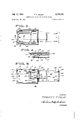
- Figure 3 is a bottom plan view of the device, completely folded for storage
- Figure 4 is a sectional view, on enlarged scale,'taken on the line 4-4 of Figure 3 and illustrating means for detachably engaging the extension table section in st'o'w'ed,
- Figure 5 is a bottom plan view of the device set up as a slopingrest platform conforming generally to the configuration of Figure 2, and illustrating optional sup-. port means.
- the exemplary embodiment includes a square or rectangular main table sec tion 10, supported at one-"end thereof by a pair of legs 12.
- the legs 12 may be joined as a unit by crosspiece'13, which .is hinged to the underside of the table section at 14 to permit inward folding.
- a conventional folding lock bracket 15 may extend between each leg and the table section, to determine and limit the extended position of the legs and prevent inadvertent folding thereof.
- the legs 12 and 16 are of equal length, whereby they may support the table section 10 as a level work surface, corresponding substantially in size and height to a conventional card table and equally versatile in use.
- the legs 16 are desirably offset laterally relative to the legs 12, so that all four legs may be simultaneously folded flush against the underside of the main table section.
- the legs 16 are positioned adjacent th'eside edges of the table section, and the legs 12 positioned inwardly thereof.
- Suitable latches 19 may be mounted on the underside of the main table section to detachably retain the legs 12 and 16 thereagainst, as by the engagement of bayonet fittings 19' suitably positioned on the legs, to prevent inadvertent unfolding thereof.
- An extension table section 20 is pivotally engaged to that end of the main table section supported by legs 16.
- transversely separated spacer blocks 22 are secured to the underside of table section 10 adjacent that end, and hinges 23 are engaged to the spacer blocks, the common hinge line of the hinges 23 being thereby disposed in general alignment with the end edge of table section 10, but somewhat below the lower surface thereof.
- Hinges 19 are engaged also to similar spacer blocks 24, attached to the underside of the extension table section 20 adjacent its inner end.
- the extension table section 20 is appreciably narrower in width than the main table section 10.
- the extension table section may be equal inlength or may be slightly shorter in length than the main table section.
- the extension table section 20 is provided with a pair of legs 25, which may be joined as a unit by a crosspiece 26. This leg unit is hingedly engaged to the underside of the extension table section at 27, and may be provided with lock brackets 28 corresponding. in structure and function to the lock brackets 15 and 18.
- the extension table section legs 25 are shorter than the main table section legs 12 and 16, by for example four inches.
- the extension table section 20 may be detachably secured in folded position below the main table section,.as by means of a spring latch 29, conveniently mounted on the'un-derside of a block 30 fastened to the underside of the table section 10.
- a small hook 32 may be fastened to the crosspiece 26 of the extension table section leg unit.
- the hook 32 is adapted to engage the spring latch 29, which thereupon servesto retain the extension table section in such position.
- extension table section it may be apertured at 33, to permit insertion of a finger to engage and displace the release lever 34 ( Figure 4) of the spring latch, whereby the latch may be pivoted out of engagement with hook 32 and the extension table section thereby released for swinging movement away therefrom.
- the main table section may be set up on its extended legs 12 and 16, with the extension table section 26 folded under and retained therebeneath' bypthe spring latch 29. So set up, the main table section may be utilized as an ordinary level work table, card table orthe like.
- the extension table section 20 may be released from the stowed position illustrated in Figure 1, byreaching through the aperture 33 thereof. torelease the spring latch. 29, and pivoted downwardly and outwardly to the dotted line position of Figure l whereat it may be supported and utilized as an extension of the level table.
- the so added extension surface may be convenient for sewing or the like, but obviously cannot support great weight without overbalancing.
- the combination table may be readily and quickly converted from the level small table configuration of Figure l to an extended sloping table adapted to accommodate a reclining person, as illustrated in Figure 2.
- the extension table section is first released and opened to the extended position shown in dotted lines in Figure l, in the manner previously described.
- the extension table section legs may then be extended at right angles to the extension table section, and locked by means of lock brackets 28.
- the main table section legs 16 may be released by unlocking the associated lock brackets 18, and then folded inwardly and upwardly against the underside of the main table section.
- the extension table section legs 25 being shorter than the main table section legs 12, the resultant configuration is an inclined, extended table or platform, six feet or more in length, supported at both ends by legs and entirely suitable for support of a reclining person in head low position.
- Means may be provided to positively engage the table sections when in extended copoplanar relationship, and rigidity the joint therebetween.
- such means may include a rectangular support 35, slidably retained immediately below the main table section by a slide strap 36 extending between side guides 37, mounted on the under surface of the main table section.
- the side guides 37 correspond in thickness to the support 35, and are spaced from each other a distance corresponding closely to the width of the support.
- the sliding support is retained also by a slide strap 38 extending between the spacer blocks 22, which may also correspond in spacing and thickness to the dimensions of the support, in order to properly serve the guiding function.
- the block mounting spring latch 29 may function as a stop for the support in retracted position, the support desirably being of such length as to extend from block 30 into slide strap 38, but not beyond the confines of the main table section 10.
- the extension table section spacer blocks 24 are similarly spaced apart to serve as side guides for the sliding support, and may mount a slide strap 39 extending therebetwecn.
- the extension table section may carry on its underside a pair of side guides 40 similar to the main table section side guides 37, and provided with a similar slide strap 42.
- the sliding support 35 is provided with finger holds 43 adjacent each end thereof, and. as will be readily understood, when the extension table section is pivoted into planar alignment 5 with the main table section, the support may be easily moved by means of its finger holds from retracted position against block 30 to a position engaging all four slide straps 36, 38, 39 and 42, as clearly shown in Figure 5.
- the support 35 may be provided with a side pin 44 adapted to encounter one of the side guides 37, to thereby limit the movement of the support in outward direction.
- the heavy support 35 engaged by the slide straps of both table sections will materially strengthen and rigidify the joint therebetween, so that the extended table may firmly and securely support a reclining person, of any weight.
- a central support for the platform extending to the floor. This may be simply provided by a suitably dimensioned rod 45, adapted to seat in a socket 46 formed in support 35, adjacent the center thereof (see Figure 5).
- Convenient stowage for the rod when not in use may be provided in a cut-away portion 47 of one of the side guides 37, and temporary retention of the rod in the cut-away portion may be insured by means of a pivotal dog 48.
- the table When converted into an extended sloping platform, then, the table may be rigidified by sliding the support 35 from retracted position against block 30 to the extended position shown in Figure 5, and the support rod 45 may be removed from cut-away portion 47 of the side guide 37, and positioned in the support socket 46, to extend therefrom to the floor as illustrated in Figure 2. So arranged, the device functions as an inclined reclining platform of exceedingly great strength.
- the table may be folded into a compact package, for convenient storage or for transportation. From the configuration of Figure 2, this may be accomplished by removing rod 45 from socket 46, and stowing the rod in the side guide cut-away portion 47 as shown in Figure 5.
- the main table section legs 12 may then be unlocked and folded inwardly against the underside thereof.
- the extension table section is freed for folding.
- the extension table section legs 25 being then folded against the underside thereof, this section may be swingably rotated inwardly to the main table section, until its hook 32 is engaged by the spring latch 29.
- the unit is then compactly folded into a package corresponding in length and width to the main table section, and of slightly greater thickness.
- the folded relationship of the device is illustrated in Figure 3.
- the device may be readily constructed of wood, metal, laminated plastic or other common material, due consideration being given to strength and overall weight. It will thus be seen that there has been provided by this invention a structure in which the various objects hereinbefore set forth, together with many practical advantages, are successfully achieved. As various possible embodiments may be made of the mechanical features of the above invention, all without departing from the scope thereof, it is to be understood that all matter hereinbefore set forth or shown in the accompanying drawings is to be interpreted as illustrative, and not in a limiting sense.
- a combination table comprising a main table section, a pair of folding legs engaged to each end of said main section, said pairs of legs being laterally offset to permit simultaneous inward folding against the underside of said main section, an extension table section pivotally engaged to one end of said main table section, said extension section being narrower than said main section, means for detachably holding said extension section in stowed position beneath said main section, means engaged to said main section and adapted to engage and maintain said extension section in extended coplanar position and rigidity the joint thercbetween. and a pair of folding legs engaged to the outer end of said extension section, said extension section legs being shorter than the legs of said main section.
- a combination table as defined in claim 1, wherein said means adapted to rigidify the joint is provided with a socket to receive the end of a support post, and including means on the underside of said main section for stowing a support post when not in use.
Landscapes
- Health & Medical Sciences (AREA)
- Engineering & Computer Science (AREA)
- Biomedical Technology (AREA)
- Life Sciences & Earth Sciences (AREA)
- Animal Behavior & Ethology (AREA)
- General Health & Medical Sciences (AREA)
- Public Health (AREA)
- Veterinary Medicine (AREA)
- Passenger Equipment (AREA)
Description
July 17, 1956 F. F. CALGY 2,755,152
COMBINATION LEVEL AND SLOPING TABLE Filed Jan. 18, 1955 2 Sheets-Sheet l INVENTOR FRANCES E CALGY ATTORNEYS July 17, 1956 Filed Jan. 18, 1955 F. F. CALGY 2,755,152
COMBINATION LEVEL AND SLOPING TABLE? 2 Sheets-Sheet 2 IN VENTOR F/PAA/c'is F cm GY WW 9m? MW ATTORNEYS United States Patent COMBINATION LEVEL AND SLOPING TABLE Frances F. Calgy, Gallatin, Tenn.
Application January 18,- 1955, Serial No. 482,478
3 Claims. (Cl. 311-52) This invention relates to tables, and in particular to a combination, multi-purpose table.
Inclined or sloping tables and platforms have been highly recommended by medical authorities for healthful relaxation, beauty aid and general physical benefit, it being found that reclining rest with the feet elevated slightly above the level of the head aids circulation and generally contributes to physical well-being. Many devices have been proposed for such purpose, but few present day households can accommodate large, unwieldy pieces of furniture adapted for only occasional and specialized use.
It is a principal object of the present invention to provide a combination, convertible multipurpose table, adapted for use as a level work table of convenient size, and also as an extended inclined platform'large and strong. enough to accommodate a reclining person.
A further object of the invention is to provide a combination level work table and inclined rest platform which may be completely folded to compact size, for ease of transportation and storage.
Another object of the invention is to provide a combination work table and sloping rest platform of simple and durable construction, readily adapted for manufacture from commonly available, inexpensive materials and standard parts. Further objects will be in part evident and in part pointed out hereinafter.
The invention and the novel features thereof may best be made clear from the following description and the accompanying drawings, in which:
Figure 1 is a side elevational view of an exemplary embodiment of the invention, set up and arranged as a.- common work table of convenient size;
Figure 2 is a side elevational view of the table' of Figure '1, converted however into an extended, sloping restplatform;
Figure 3 is a bottom plan view of the device, completely folded for storage;
Figure 4 is a sectional view, on enlarged scale,'taken on the line 4-4 of Figure 3 and illustrating means for detachably engaging the extension table section in st'o'w'ed,
out of the Way position beneath the main table section, and
Figure 5 is a bottom plan view of the device set up as a slopingrest platform conforming generally to the configuration of Figure 2, and illustrating optional sup-. port means.
Referring to the drawings in detail, the exemplary embodiment includes a square or rectangular main table sec tion 10, supported at one-"end thereof by a pair of legs 12. The legs 12 may be joined as a unit by crosspiece'13, which .is hinged to the underside of the table section at 14 to permit inward folding. A conventional folding lock bracket 15 may extend between each leg and the table section, to determine and limit the extended position of the legs and prevent inadvertent folding thereof.
At the other end of the table section is provided a pair of legs 16, also hinged at 17 to the underside of the table section for inward folding, and each provided 2,755,152 Patented July 17, 1956 with a folding lock bracket 18. The legs 12 and 16 are of equal length, whereby they may support the table section 10 as a level work surface, corresponding substantially in size and height to a conventional card table and equally versatile in use. As illustrated in Figures 3 and 5, the legs 16 are desirably offset laterally relative to the legs 12, so that all four legs may be simultaneously folded flush against the underside of the main table section. In the exemplary embodiment, the legs 16 are positioned adjacent th'eside edges of the table section, and the legs 12 positioned inwardly thereof. Suitable latches 19 (Fig ure 5) may be mounted on the underside of the main table section to detachably retain the legs 12 and 16 thereagainst, as by the engagement of bayonet fittings 19' suitably positioned on the legs, to prevent inadvertent unfolding thereof.
An extension table section 20 is pivotally engaged to that end of the main table section supported by legs 16. As bestshown in Figures 1 and 5, transversely separated spacer blocks 22 are secured to the underside of table section 10 adjacent that end, and hinges 23 are engaged to the spacer blocks, the common hinge line of the hinges 23 being thereby disposed in general alignment with the end edge of table section 10, but somewhat below the lower surface thereof. Hinges 19 are engaged also to similar spacer blocks 24, attached to the underside of the extension table section 20 adjacent its inner end. In order to clear the legs 16, the extension table section 20 is appreciably narrower in width than the main table section 10. The extension table section may be equal inlength or may be slightly shorter in length than the main table section.
At its outer end, the extension table section 20 is provided with a pair of legs 25, which may be joined as a unit by a crosspiece 26. This leg unit is hingedly engaged to the underside of the extension table section at 27, and may be provided with lock brackets 28 corresponding. in structure and function to the lock brackets 15 and 18. The extension table section legs 25 are shorter than the main table section legs 12 and 16, by for example four inches.
The extension table section 20 may be detachably secured in folded position below the main table section,.as by means of a spring latch 29, conveniently mounted on the'un-derside of a block 30 fastened to the underside of the table section 10. To cooperate with the spring latch 29, a small hook 32 may be fastened to the crosspiece 26 of the extension table section leg unit. As best shown iii-Figures l and 4, when the extension table section is folded up below the main table section, the hook 32 is adapted to engage the spring latch 29, which thereupon servesto retain the extension table section in such position. To provide for ready release of the extension table section, it may be apertured at 33, to permit insertion of a finger to engage and displace the release lever 34 (Figure 4) of the spring latch, whereby the latch may be pivoted out of engagement with hook 32 and the extension table section thereby released for swinging movement away therefrom.
As illustrated in Figure l, the main table section may be set up on its extended legs 12 and 16, with the extension table section 26 folded under and retained therebeneath' bypthe spring latch 29. So set up, the main table section may be utilized as an ordinary level work table, card table orthe like. If desired, the extension table section 20 may be released from the stowed position illustrated in Figure 1, byreaching through the aperture 33 thereof. torelease the spring latch. 29, and pivoted downwardly and outwardly to the dotted line position of Figure l whereat it may be supported and utilized as an extension of the level table. The so added extension surface may be convenient for sewing or the like, but obviously cannot support great weight without overbalancing.
The combination table may be readily and quickly converted from the level small table configuration of Figure l to an extended sloping table adapted to accommodate a reclining person, as illustrated in Figure 2. For such conversion, the extension table section is first released and opened to the extended position shown in dotted lines in Figure l, in the manner previously described. The extension table section legs may then be extended at right angles to the extension table section, and locked by means of lock brackets 28. The main table section legs 16 may be released by unlocking the associated lock brackets 18, and then folded inwardly and upwardly against the underside of the main table section. The extension table section legs 25 being shorter than the main table section legs 12, the resultant configuration is an inclined, extended table or platform, six feet or more in length, supported at both ends by legs and entirely suitable for support of a reclining person in head low position.
Means may be provided to positively engage the table sections when in extended copoplanar relationship, and rigidity the joint therebetween. Most simply, such means may include a rectangular support 35, slidably retained immediately below the main table section by a slide strap 36 extending between side guides 37, mounted on the under surface of the main table section. Preferably, the side guides 37 correspond in thickness to the support 35, and are spaced from each other a distance corresponding closely to the width of the support. The sliding support is retained also by a slide strap 38 extending between the spacer blocks 22, which may also correspond in spacing and thickness to the dimensions of the support, in order to properly serve the guiding function. The block mounting spring latch 29 may function as a stop for the support in retracted position, the support desirably being of such length as to extend from block 30 into slide strap 38, but not beyond the confines of the main table section 10.
The extension table section spacer blocks 24 are similarly spaced apart to serve as side guides for the sliding support, and may mount a slide strap 39 extending therebetwecn. At a position suitably spaced longitudinally from spacer blocks 24, the extension table section may carry on its underside a pair of side guides 40 similar to the main table section side guides 37, and provided with a similar slide strap 42. On its underside, the sliding support 35 is provided with finger holds 43 adjacent each end thereof, and. as will be readily understood, when the extension table section is pivoted into planar alignment 5 with the main table section, the support may be easily moved by means of its finger holds from retracted position against block 30 to a position engaging all four slide straps 36, 38, 39 and 42, as clearly shown in Figure 5. The support 35 may be provided with a side pin 44 adapted to encounter one of the side guides 37, to thereby limit the movement of the support in outward direction.
The heavy support 35 engaged by the slide straps of both table sections will materially strengthen and rigidify the joint therebetween, so that the extended table may firmly and securely support a reclining person, of any weight. I n rare cases, it may be desirable to provide also a central support for the platform, extending to the floor. This may be simply provided by a suitably dimensioned rod 45, adapted to seat in a socket 46 formed in support 35, adjacent the center thereof (see Figure 5). Convenient stowage for the rod when not in use may be provided in a cut-away portion 47 of one of the side guides 37, and temporary retention of the rod in the cut-away portion may be insured by means of a pivotal dog 48. When converted into an extended sloping platform, then, the table may be rigidified by sliding the support 35 from retracted position against block 30 to the extended position shown in Figure 5, and the support rod 45 may be removed from cut-away portion 47 of the side guide 37, and positioned in the support socket 46, to extend therefrom to the floor as illustrated in Figure 2. So arranged, the device functions as an inclined reclining platform of exceedingly great strength.
The principal configurations of the table are illustrated in Figures 1 and 2. As a further important feature of the invention, the table may be folded into a compact package, for convenient storage or for transportation. From the configuration of Figure 2, this may be accomplished by removing rod 45 from socket 46, and stowing the rod in the side guide cut-away portion 47 as shown in Figure 5. The main table section legs 12 may then be unlocked and folded inwardly against the underside thereof. By retracting the sliding support into engagement with the main table section block 30, the extension table section is freed for folding. The extension table section legs 25 being then folded against the underside thereof, this section may be swingably rotated inwardly to the main table section, until its hook 32 is engaged by the spring latch 29. The unit is then compactly folded into a package corresponding in length and width to the main table section, and of slightly greater thickness. The folded relationship of the device is illustrated in Figure 3.
As will be evident, the device may be readily constructed of wood, metal, laminated plastic or other common material, due consideration being given to strength and overall weight. It will thus be seen that there has been provided by this invention a structure in which the various objects hereinbefore set forth, together with many practical advantages, are successfully achieved. As various possible embodiments may be made of the mechanical features of the above invention, all without departing from the scope thereof, it is to be understood that all matter hereinbefore set forth or shown in the accompanying drawings is to be interpreted as illustrative, and not in a limiting sense.
I claim:
I. A combination table comprising a main table section, a pair of folding legs engaged to each end of said main section, said pairs of legs being laterally offset to permit simultaneous inward folding against the underside of said main section, an extension table section pivotally engaged to one end of said main table section, said extension section being narrower than said main section, means for detachably holding said extension section in stowed position beneath said main section, means engaged to said main section and adapted to engage and maintain said extension section in extended coplanar position and rigidity the joint thercbetween. and a pair of folding legs engaged to the outer end of said extension section, said extension section legs being shorter than the legs of said main section.
2. A combination table as defined in claim 1, wherein said table sections are pivotally engaged on a transverse hinge axis disposed below the level of the underside of said main section.
3. A combination table as defined in claim 1, wherein said means adapted to rigidify the joint is provided with a socket to receive the end of a support post, and including means on the underside of said main section for stowing a support post when not in use.
References Cited in the file of this patent UNITED STATES PATENTS 1,595,574 SChlappe Aug. 10, 1926 1,599,247 Ridabock Sept. 7, 1926 ,990,600 Fridheim Feb. 12, 1935 2,579,783 Branto Dec. 25, 1951 2,658,754 Courtney Nov. 10, 1953 2,699,977 Breslow Jan. 16, 1955
Priority Applications (1)
| Application Number | Priority Date | Filing Date | Title |
|---|---|---|---|
| US482478A US2755152A (en) | 1955-01-18 | 1955-01-18 | Combination level and sloping table |
Applications Claiming Priority (1)
| Application Number | Priority Date | Filing Date | Title |
|---|---|---|---|
| US482478A US2755152A (en) | 1955-01-18 | 1955-01-18 | Combination level and sloping table |
Publications (1)
| Publication Number | Publication Date |
|---|---|
| US2755152A true US2755152A (en) | 1956-07-17 |
Family
ID=23916247
Family Applications (1)
| Application Number | Title | Priority Date | Filing Date |
|---|---|---|---|
| US482478A Expired - Lifetime US2755152A (en) | 1955-01-18 | 1955-01-18 | Combination level and sloping table |
Country Status (1)
| Country | Link |
|---|---|
| US (1) | US2755152A (en) |
Cited By (8)
| Publication number | Priority date | Publication date | Assignee | Title |
|---|---|---|---|---|
| US2799546A (en) * | 1956-09-13 | 1957-07-16 | Michael J Lowry | Foldable, extensible table |
| US3859930A (en) * | 1972-03-28 | 1975-01-14 | Peter G Sherwin | Tiltable tray with pivotally mounted legs having extensible feet |
| US4546948A (en) * | 1983-03-21 | 1985-10-15 | Summagraphics Corporation | Easel |
| DE3712994A1 (en) * | 1986-10-10 | 1988-04-21 | Southco | ARRANGEMENT WITH ROTATING JOINT AND FALLING Pawl |
| US5373794A (en) * | 1989-12-11 | 1994-12-20 | Wiberg; Ole | Furniture extension mechanism |
| US5443532A (en) * | 1994-01-04 | 1995-08-22 | Hudak; Thomas P. | Apparatus for enhancing sexual intimacy |
| US5540158A (en) * | 1994-08-29 | 1996-07-30 | Ford; Henry E. | Sectional folding table |
| US11191350B2 (en) * | 2020-11-24 | 2021-12-07 | Space Innovation Labs Llc | Cantilever table for mounting to vehicle cargo area |
Citations (6)
| Publication number | Priority date | Publication date | Assignee | Title |
|---|---|---|---|---|
| US1595574A (en) * | 1925-10-21 | 1926-08-10 | Marie J Quevli | Food chopper |
| US1599247A (en) * | 1926-02-01 | 1926-09-07 | Alice B Ridabock | Combined card and invalid table |
| US1990600A (en) * | 1934-03-22 | 1935-02-12 | Ester A Fridheim | Massage table |
| US2579783A (en) * | 1951-03-06 | 1951-12-25 | Andrew F Branto | Foldable portable chiropractor's table |
| US2658754A (en) * | 1950-11-07 | 1953-11-10 | William F Courtney | Foldable exercising and resting table |
| US2699977A (en) * | 1953-04-09 | 1955-01-18 | Breslow Leon | Folding sectional top table |
-
1955
- 1955-01-18 US US482478A patent/US2755152A/en not_active Expired - Lifetime
Patent Citations (6)
| Publication number | Priority date | Publication date | Assignee | Title |
|---|---|---|---|---|
| US1595574A (en) * | 1925-10-21 | 1926-08-10 | Marie J Quevli | Food chopper |
| US1599247A (en) * | 1926-02-01 | 1926-09-07 | Alice B Ridabock | Combined card and invalid table |
| US1990600A (en) * | 1934-03-22 | 1935-02-12 | Ester A Fridheim | Massage table |
| US2658754A (en) * | 1950-11-07 | 1953-11-10 | William F Courtney | Foldable exercising and resting table |
| US2579783A (en) * | 1951-03-06 | 1951-12-25 | Andrew F Branto | Foldable portable chiropractor's table |
| US2699977A (en) * | 1953-04-09 | 1955-01-18 | Breslow Leon | Folding sectional top table |
Cited By (8)
| Publication number | Priority date | Publication date | Assignee | Title |
|---|---|---|---|---|
| US2799546A (en) * | 1956-09-13 | 1957-07-16 | Michael J Lowry | Foldable, extensible table |
| US3859930A (en) * | 1972-03-28 | 1975-01-14 | Peter G Sherwin | Tiltable tray with pivotally mounted legs having extensible feet |
| US4546948A (en) * | 1983-03-21 | 1985-10-15 | Summagraphics Corporation | Easel |
| DE3712994A1 (en) * | 1986-10-10 | 1988-04-21 | Southco | ARRANGEMENT WITH ROTATING JOINT AND FALLING Pawl |
| US5373794A (en) * | 1989-12-11 | 1994-12-20 | Wiberg; Ole | Furniture extension mechanism |
| US5443532A (en) * | 1994-01-04 | 1995-08-22 | Hudak; Thomas P. | Apparatus for enhancing sexual intimacy |
| US5540158A (en) * | 1994-08-29 | 1996-07-30 | Ford; Henry E. | Sectional folding table |
| US11191350B2 (en) * | 2020-11-24 | 2021-12-07 | Space Innovation Labs Llc | Cantilever table for mounting to vehicle cargo area |
Similar Documents
| Publication | Publication Date | Title |
|---|---|---|
| US6705234B1 (en) | Folding table | |
| US4193630A (en) | Self containing collapsible high chair | |
| US3467033A (en) | Folding stool | |
| US3357729A (en) | Folding brace lock for table leg | |
| US4034518A (en) | Portable cot and table convertible into carrying case | |
| US2766812A (en) | Folding table and seat assembly | |
| US3420571A (en) | Collapsible combination chair and table | |
| US3646895A (en) | Table with folding legs | |
| US3267886A (en) | Leg mounting means for furniture | |
| US4829910A (en) | Folding table for a recreational vehicle | |
| US2522642A (en) | Foldable table and seat assembly | |
| US2692636A (en) | Combination automobile mechanic's creeper and stool | |
| US2611909A (en) | Portable guard | |
| US1614187A (en) | Adjustable-leg foldable table | |
| US2755152A (en) | Combination level and sloping table | |
| CN208550571U (en) | a folding seat | |
| US3399925A (en) | Artist's bench | |
| US2436730A (en) | Folding table and benches | |
| US2216317A (en) | Combination bed and chair | |
| US3087442A (en) | Convertible coffee-dining table | |
| US2311798A (en) | Folding table | |
| US3079167A (en) | Foldable support means | |
| US1985189A (en) | Kitchen cabinet | |
| US2861731A (en) | Folding porch | |
| US2291967A (en) | Collapsible card table |