US273717A - Oil-stove - Google Patents
Oil-stove Download PDFInfo
- Publication number
- US273717A US273717A US273717DA US273717A US 273717 A US273717 A US 273717A US 273717D A US273717D A US 273717DA US 273717 A US273717 A US 273717A
- Authority
- US
- United States
- Prior art keywords
- wick
- cone
- oil
- tube
- raiser
- Prior art date
- Legal status (The legal status is an assumption and is not a legal conclusion. Google has not performed a legal analysis and makes no representation as to the accuracy of the status listed.)
- Expired - Lifetime
Links
- 238000010276 construction Methods 0.000 description 6
- 238000004140 cleaning Methods 0.000 description 4
- 230000000284 resting Effects 0.000 description 4
- 229910001018 Cast iron Inorganic materials 0.000 description 2
- 208000007101 Muscle Cramp Diseases 0.000 description 2
- 206010028334 Muscle spasms Diseases 0.000 description 2
- 238000002485 combustion reaction Methods 0.000 description 2
- 238000010411 cooking Methods 0.000 description 2
- 230000000994 depressed Effects 0.000 description 2
- 229910052760 oxygen Inorganic materials 0.000 description 2
- MYMOFIZGZYHOMD-UHFFFAOYSA-N oxygen Chemical compound O=O MYMOFIZGZYHOMD-UHFFFAOYSA-N 0.000 description 2
- 239000001301 oxygen Substances 0.000 description 2
Images

Classifications
-
- F—MECHANICAL ENGINEERING; LIGHTING; HEATING; WEAPONS; BLASTING
- F23—COMBUSTION APPARATUS; COMBUSTION PROCESSES
- F23D—BURNERS
- F23D11/00—Burners using a direct spraying action of liquid droplets or vaporised liquid into the combustion space
- F23D11/36—Details, e.g. burner cooling means, noise reduction means
- F23D11/44—Preheating devices; Vaporising devices
Definitions
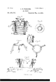
- Figure l is an upright elevation.
- Fig. 2 is a vertical section.
- Fig. 3 is a vertical section of burner.
- Fig. 4 is an under view of cone.
- Fig. 5 is a view of the cone-supporter.
- Fig. 6 is a top View of same.
- Fig. 7 is a vertical sectional view of'the top of the wick-raiser.
- Fig. 8 is a view of lower portion of wick-raiser, showing one of the slots.
- the nature and object of this invention is to provide a safe and reliable oil-stove.
- Fig. 1 is shown the stove, ready for use, having the oil-fountain A,'oil-pipe B, leading from oil-fountain to wick-reservoir O, drum D, and base Y, upon which base rest the posts Z Z, these posts supporting the superstructure.
- the dome D is hinged to the posts at g 9.
- On top of the drum is the open or turreted cap X, upon which is placed the cooking utensil.
- I use no chimney, the drum D answering the double purpose of chimney and drum.
- E is the central air-tube, having the spiral or screw thread a.
- F is the wick-tube, embracing the central air-tn be, E, and having spiral thread out thereon to correspond with that on central air-tube.
- To outside of wick-tube is fastened the wick G.
- H is the slotted wick-raiser, annular in form, and at its upper end it is attached to the handled cast-iron ring J, having the handles KK attached thereto for the purpose of turning it.
- I l are arms attached to the wick-tube F, at its lower end, and passing through the slots L L in the wick-raiser H.
- the wick-raiser are the two slots L L, directly opposite each other, into which the arms II, extending from the wick-tube F, work.
- One slot is shown in Fig. 8. The other is directly opposite.
- N is the cone-supporter, having the legs b c d,ofdifi'erentlengths. Theselegsjustfitwithin the central air-tube, E, and the difierentlen gths (No model.)
- the cone-supporter can be raised or lowered by turning it the same as a screw. It also holds the cone in a horizontal position.
- Fig. 6 is shown the top view of the conesupporter, showing the notchesc 0, cut on the inside, directly opposite each other.
- M is the inverted hollow cone, resting upon its supporter N.
- the two arms 1' '5. These arlnspass through the slots 6 0 in the supporter.
- the under side of the ring of the supporter is made with an incline, t 25, extending in the same direction from the slots e e, and when the arms it'have passed through the slots e e the coneis turned in one direction, which causes the arms t' t' to engage with the surface of the inclines t t.
- the cone is held in position.
- a perforated diaphragm, O At the upper surface of the cone is a perforated diaphragm, O, and there is also one, WV, at P, at lower end of cone, covering the upper end of internal air-tube, E, and also the annular perforated diaphragm Q is attached to the upper end of wick-raiser H.
- This diaphragm Q is attached to the wick-raiser by reversing the upper edge of wick-raiser and turning up the inner edge of diaphragm Q, then interlocking the two edges thus formed, and then pressing the two together, as shown at s s, Fig. 7.
- V is the dome, surrounding the burner for the purpose of deflecting the air onto the flame, leaving an annular opening between it and the cone M.
- the two arms I I interlocking with the two slots L L insures the speedy and safe raising and lowering of the wick at all times,and also enables me to apply the power to raise and lower the wick at two points directly ppposite each other at the same time, and thus all cramp ing and hitching in raising the wick are obviated.
- the means employed to attach and detach the cone M enables it to be removed without difliculty when desired to cleanjt, and the peculiar construction of the cone-supporter N enables the cone to be elevated or depressed at pleasure.
- the cone-supporter N having legs of unequal lengths, in combination with an Argand burner, for the purpose of resting against the inside of the air-tube and of supporting the cone, substantially as shown and described.
- a detachable or adj ustable central air-supplyingcone, M provided with a perforateddiaphragm, O, substantially as and for the purpose described.
Description
(No Model.) 2 Sheets-Sheet 1. J. E. FLEMING.
OIL STOVE.
No. 273,717. Patented Mar. 13,1883.
N. PETERS, Pmwumu mr. Waxhmgmn, n. c.
(No Mdel.) J. E. FLEMING. 2 Sheets-Sheet 2.
OIL STOVE.
No. 273,717. Patented Mar. 13,1883.
Ill
STATES JOHN E. FLEMING, OF CHICAGO, ILLINOIS.
OIL-STOVE.
SPECIFICATION formingpart of Letters Patent No. 273,717, dated March 18,. 1888.
Application filed May 6, 1882.
To all whom it may concrrn:
Be it known that I, JOHN E. FLEMING, a
citizen of the United States, residing at the city of- Chicago, in the State of Illinois, have made certain Improvements in Oil-Stoves, of which the following is a specification.
Figure l is an upright elevation. Fig. 2 is a vertical section. Fig. 3 is a vertical section of burner. Fig. 4 is an under view of cone. Fig. 5 is a view of the cone-supporter. Fig. 6 is a top View of same. Fig. 7 is a vertical sectional view of'the top of the wick-raiser. Fig. 8 is a view of lower portion of wick-raiser, showing one of the slots.
Similar letters of reference in the different drawings refer to similar parts.
The nature and object of this invention is to provide a safe and reliable oil-stove.
In Fig. 1 is shown the stove, ready for use, having the oil-fountain A,'oil-pipe B, leading from oil-fountain to wick-reservoir O, drum D, and base Y, upon which base rest the posts Z Z, these posts supporting the superstructure. The dome D is hinged to the posts at g 9. On top of the drum is the open or turreted cap X, upon which is placed the cooking utensil. I use no chimney, the drum D answering the double purpose of chimney and drum. I use the Argand burner, as I consider this kind oflburner capable of producing the best resu ts.
E is the central air-tube, having the spiral or screw thread a.
F is the wick-tube, embracing the central air-tn be, E, and having spiral thread out thereon to correspond with that on central air-tube. To outside of wick-tube is fastened the wick G.
H is the slotted wick-raiser, annular in form, and at its upper end it is attached to the handled cast-iron ring J, having the handles KK attached thereto for the purpose of turning it.
I l are arms attached to the wick-tube F, at its lower end, and passing through the slots L L in the wick-raiser H. In the wick-raiser are the two slots L L, directly opposite each other, into which the arms II, extending from the wick-tube F, work. One slot is shown in Fig. 8. The other is directly opposite.
N is the cone-supporter, having the legs b c d,ofdifi'erentlengths. Theselegsjustfitwithin the central air-tube, E, and the difierentlen gths (No model.)
of legs enable them to fit or work between the screw-threads a a. The cone-supporter can be raised or lowered by turning it the same as a screw. It also holds the cone in a horizontal position.
In Fig. 6 is shown the top view of the conesupporter, showing the notchesc 0, cut on the inside, directly opposite each other.
M is the inverted hollow cone, resting upon its supporter N. At the small end of the cone are the two arms 1' '5. These arlnspass through the slots 6 0 in the supporter. The under side of the ring of the supporter is made with an incline, t 25, extending in the same direction from the slots e e, and when the arms it'have passed through the slots e e the coneis turned in one direction, which causes the arms t' t' to engage with the surface of the inclines t t. Thus the cone is held in position. At the upper surface of the cone is a perforated diaphragm, O, and there is also one, WV, at P, at lower end of cone, covering the upper end of internal air-tube, E, and also the annular perforated diaphragm Q is attached to the upper end of wick-raiser H. This diaphragm Q is attached to the wick-raiser by reversing the upper edge of wick-raiser and turning up the inner edge of diaphragm Q, then interlocking the two edges thus formed, and then pressing the two together, as shown at s s, Fig. 7.
V is the dome, surrounding the burner for the purpose of deflecting the air onto the flame, leaving an annular opening between it and the cone M.
Oil enters the wick-reservoir through the tube B from the oil-fountain A, and by turning the arms K K, the wick-raiser being interlocked at opposite points with the wicktube F, the wick is raised or lowered at pleasure. The two arms I I interlocking with the two slots L L insures the speedy and safe raising and lowering of the wick at all times,and also enables me to apply the power to raise and lower the wick at two points directly ppposite each other at the same time, and thus all cramp ing and hitching in raising the wick are obviated.
The means employed to attach and detach the cone M enables it to be removed without difliculty when desired to cleanjt, and the peculiar construction of the cone-supporter N enables the cone to be elevated or depressed at pleasure.
I consider the employment of the removable air-supplying cone M an original and valuable feature in the construction and operation of oil-stoves, it being the fact that great inconvenience is encountered in cleaning such part or parts when of the ordinary construction, and that it is necessary to clean such part or parts frequently in order to insure a free passage of oxygen to the flame, and thereby a perfect combustion. Y
1. The cone-supporter N, having legs of unequal lengths, in combination with an Argand burner, for the purpose of resting against the inside of the air-tube and of supporting the cone, substantially as shown and described.
2. In an Argand burner, the combination of the cone M, having lugs i i, and cone-supporter N, having slots 0 e and inclined surface t t, for the purpose of attaching and detaching the cone from its supporter, substantially as shown and described.
3. In a burner, the combination of the slotted wick-raiser H, armed ring J, and annular diaphragm Q, substantially as shown.
4. The combination and arrangement of the air-tube E, wick-tube F, and wick-raiser H, with the removable or adjustable cone M, substantially as and for the purpose described.
5. The combination of the drum D and dome Vof an oil-stove, with an Argand burner having the removable cone M, the adjustable conesupporter N, and internal air-tube, E, substantially as shown and described.
6. In combination with the wickfeeding mechanism of an Argand burner, a detachable or adj ustable central air-supplyingcone, M, provided with a perforateddiaphragm, O, substantially as and for the purpose described.
JOHN E. FLEMING.
Witnesses:
JAS. A. OoWLEs, HENRY S. OSBORNE.
Publications (1)
| Publication Number | Publication Date |
|---|---|
| US273717A true US273717A (en) | 1883-03-13 |
Family
ID=2342947
Family Applications (1)
| Application Number | Title | Priority Date | Filing Date |
|---|---|---|---|
| US273717D Expired - Lifetime US273717A (en) | Oil-stove |
Country Status (1)
| Country | Link |
|---|---|
| US (1) | US273717A (en) |
-
0
- US US273717D patent/US273717A/en not_active Expired - Lifetime
Similar Documents
| Publication | Publication Date | Title |
|---|---|---|
| US273717A (en) | Oil-stove | |
| US427819A (en) | Hydrocarbon-burner | |
| US1170606A (en) | Oil-stove. | |
| US200627A (en) | Improvement in lamp-burners | |
| US193796A (en) | Improvement in vapor-burners for heating purposes | |
| US2091A (en) | Argand lamp | |
| US188490A (en) | Improvement in lamp-burners | |
| US1070604A (en) | Hydrocarbon-burner. | |
| US569501A (en) | Joseph kampf | |
| US128325A (en) | Improvement in argand lamp-burners | |
| US477366A (en) | o o o o o o | |
| US299301A (en) | Lamp-burner | |
| US638686A (en) | Lamp-burner for incandescent mantles. | |
| US40222A (en) | Improvement in lamps | |
| US617568A (en) | Vapor-burner | |
| US260888A (en) | James musgeave | |
| US71002A (en) | Improvement in gas heating apparatus | |
| US41300A (en) | Improvement in coal-oil lamps | |
| US196901A (en) | Improvement in lamp-burners | |
| US1092262A (en) | Blue-flame oil-burner. | |
| US131578A (en) | Improvement in lamp-heaters | |
| US302658A (en) | Thomas hipwell | |
| US855824A (en) | Incandescent burner for liquid hydrocarbons. | |
| US436093A (en) | atwood | |
| US643807A (en) | Petroleum incandescent-lamp burner. |