US273680A - g-uerber - Google Patents
g-uerber Download PDFInfo
- Publication number
- US273680A US273680A US273680DA US273680A US 273680 A US273680 A US 273680A US 273680D A US273680D A US 273680DA US 273680 A US273680 A US 273680A
- Authority
- US
- United States
- Prior art keywords
- valve
- pressure
- port
- valves
- chamber
- Prior art date
- Legal status (The legal status is an assumption and is not a legal conclusion. Google has not performed a legal analysis and makes no representation as to the accuracy of the status listed.)
- Expired - Lifetime
Links
- 239000002699 waste material Substances 0.000 description 5
- 238000010276 construction Methods 0.000 description 3
- 230000008602 contraction Effects 0.000 description 2
- 239000012530 fluid Substances 0.000 description 2
- 230000001421 changed effect Effects 0.000 description 1
- 230000000694 effects Effects 0.000 description 1
- 230000008520 organization Effects 0.000 description 1
Images

Classifications
-
- F—MECHANICAL ENGINEERING; LIGHTING; HEATING; WEAPONS; BLASTING
- F16—ENGINEERING ELEMENTS AND UNITS; GENERAL MEASURES FOR PRODUCING AND MAINTAINING EFFECTIVE FUNCTIONING OF MACHINES OR INSTALLATIONS; THERMAL INSULATION IN GENERAL
- F16K—VALVES; TAPS; COCKS; ACTUATING-FLOATS; DEVICES FOR VENTING OR AERATING
- F16K11/00—Multiple-way valves, e.g. mixing valves; Pipe fittings incorporating such valves
- F16K11/10—Multiple-way valves, e.g. mixing valves; Pipe fittings incorporating such valves with two or more closure members not moving as a unit
- F16K11/14—Multiple-way valves, e.g. mixing valves; Pipe fittings incorporating such valves with two or more closure members not moving as a unit operated by one actuating member, e.g. a handle
- F16K11/18—Multiple-way valves, e.g. mixing valves; Pipe fittings incorporating such valves with two or more closure members not moving as a unit operated by one actuating member, e.g. a handle with separate operating movements for separate closure members
-
- F—MECHANICAL ENGINEERING; LIGHTING; HEATING; WEAPONS; BLASTING
- F15—FLUID-PRESSURE ACTUATORS; HYDRAULICS OR PNEUMATICS IN GENERAL
- F15B—SYSTEMS ACTING BY MEANS OF FLUIDS IN GENERAL; FLUID-PRESSURE ACTUATORS, e.g. SERVOMOTORS; DETAILS OF FLUID-PRESSURE SYSTEMS, NOT OTHERWISE PROVIDED FOR
- F15B13/00—Details of servomotor systems ; Valves for servomotor systems
- F15B13/02—Fluid distribution or supply devices characterised by their adaptation to the control of servomotors
- F15B13/04—Fluid distribution or supply devices characterised by their adaptation to the control of servomotors for use with a single servomotor
-
- Y—GENERAL TAGGING OF NEW TECHNOLOGICAL DEVELOPMENTS; GENERAL TAGGING OF CROSS-SECTIONAL TECHNOLOGIES SPANNING OVER SEVERAL SECTIONS OF THE IPC; TECHNICAL SUBJECTS COVERED BY FORMER USPC CROSS-REFERENCE ART COLLECTIONS [XRACs] AND DIGESTS
- Y10—TECHNICAL SUBJECTS COVERED BY FORMER USPC
- Y10T—TECHNICAL SUBJECTS COVERED BY FORMER US CLASSIFICATION
- Y10T137/00—Fluid handling
- Y10T137/8593—Systems
- Y10T137/86919—Sequentially closing and opening alternately seating flow controllers
-
- Y—GENERAL TAGGING OF NEW TECHNOLOGICAL DEVELOPMENTS; GENERAL TAGGING OF CROSS-SECTIONAL TECHNOLOGIES SPANNING OVER SEVERAL SECTIONS OF THE IPC; TECHNICAL SUBJECTS COVERED BY FORMER USPC CROSS-REFERENCE ART COLLECTIONS [XRACs] AND DIGESTS
- Y10—TECHNICAL SUBJECTS COVERED BY FORMER USPC
- Y10T—TECHNICAL SUBJECTS COVERED BY FORMER US CLASSIFICATION
- Y10T137/00—Fluid handling
- Y10T137/8593—Systems
- Y10T137/87056—With selective motion for plural valve actuator
- Y10T137/87064—Oppositely movable cam surfaces
-
- Y—GENERAL TAGGING OF NEW TECHNOLOGICAL DEVELOPMENTS; GENERAL TAGGING OF CROSS-SECTIONAL TECHNOLOGIES SPANNING OVER SEVERAL SECTIONS OF THE IPC; TECHNICAL SUBJECTS COVERED BY FORMER USPC CROSS-REFERENCE ART COLLECTIONS [XRACs] AND DIGESTS
- Y10—TECHNICAL SUBJECTS COVERED BY FORMER USPC
- Y10T—TECHNICAL SUBJECTS COVERED BY FORMER US CLASSIFICATION
- Y10T137/00—Fluid handling
- Y10T137/8593—Systems
- Y10T137/87169—Supply and exhaust
Definitions
- My present invention relates to certain improvements in the class of valves referred to in Patent No. 229,341, granted June 29,1880, to Harvey Tilden and myself.
- This Tilden and Guerbervalve when properly constructed, performs well all the functions assigned toit; but it has been found in practical use that, apparently on account of expansions and contractions, the two lower valves do not always come to their seats exactly at the same time, or, in other words, that sometimes when one of said two lower valves is seated the other will stand a little clear of its seat, so that leakage results or frequent readjustment is necessary.
- This ditculty I have overcome by making ⁇ the middle valve ofthe three ofthe Tilden and Guerber device in the form or of the construction of a piston in the present device, and arrange it in a tubular seat or case 0f such length that it will always keep the port or chamber in which it works closed, but will perform the balancing function desired; and l have also chan ged the arrangement ot' ports or passages, so as to enable thevalve thus made to perform the work desired in admitting and releasing fluid-pressure, or in providing ⁇ for the passage of fluids.
- this valve is chiefly designed for ⁇ use as a part of a hydraulic railway switch or signal apparatus, I will, for convenience, so describe it; but in doing so I do not mean to limit myself in the uses to which hereunder I may apply it.
- the valve-case, Figs. 1 and 2 is made with six chambers, A,B, B', C, D, and D', separated from each other by interior diaphragms, as shown, but with a port, a, leading from A to B, a port, a', leading from A to B', a tubular piston-case, b, between B and C, and a like case, b', between B' and C, and ports c c', leading, respectively, from C to l) and C to D' also, a side port or passage, P, made in the wall or shell ot' the valve case, or exterior thereto, leads, as indicated by dotted lines, from the chamber B' to D' and a like side )ort or )assage, P', Fig.
- the valve-stem It carries a valve, s, to open and close the port a, and a pistomp, packed as against pressure above and below, which piston, working in the tubular case b, prevents communication from B to C, or the reverse, and the walls of b are made long enough, so that thepiston p shall always' keep it closed; and the stem R also carries a valve, s', which opens and closes the' port c.'v
- the other valve-stem, R' carries like valves, s2 s3, and piston p', all of which sustain a like relation to the ports a' c' and case b', respectively.
- the two valve-stems are connected byA a vibratory arm, R2, so that both are moved simultaneously, but in opposite directions.
- This device is designed foruse with a single-throw cylinder and piston, or one in which fluid-pressure is applied on one side of a piston to impart to it motion in one direction, and the pressure is released or discharged to permit motion in the other direction.
- Either pipe A' or C may be the supply and the other the Waste, (which also is true of Fig. 1;) but preferably A' is the supply-pipe and C the Waste or discharge.
Landscapes
- Engineering & Computer Science (AREA)
- General Engineering & Computer Science (AREA)
- Mechanical Engineering (AREA)
- Physics & Mathematics (AREA)
- Fluid Mechanics (AREA)
- Multiple-Way Valves (AREA)
Description
(No Model.) 2 Sheets-Sheet 1.
1:". S. GUERBER.
VALVULAR APPRATUS. No. 273,680. Patented Mar.6,1883.
LLI'
alli; "P d (No Model.) 2 Sheets-Sheet 2. F. S. GUERBER.
VALVULAR APPARATUS. No.` 273,680. Patented Malm, 1883.
1 l l i l l UNITE STATES FREDERICK S. GUERBER, OF PITTSBURG, PENNSYLVANIA, ASSIGNOR TO THE UNION SWITCH AND SIGNAL COMPANY, OF SAME PLACE.
VALVULAR APPARATUS.
SPECIFICATION forming part of Letters Patent No. 273,680, dated March 6, 1883.
Application filed November 13,1882. (No model.)
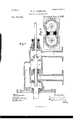
To all whom it may concern Be it known that I, FREDERICK S. GUER- BER, of Pittsburg, county of Allegheny, State of Pennsylvania, have invented or discovered a. new and useful Improvement in Valvular Apparatus; and I do hereby declare the following to be a full, clear, concise, and exactdescription thereof', reference being had to the accompanying drawings, making a part of this specification, in which--likeletters indicating like partsy Figure 1, Sheet 1, represents a vertical sectional elevation of my improved valve device. Fig. 2, Sheet 2, is a sectional view in the plane ofthe line x as ot' Fig. 1, and Fig. 3 shows in sectional elevation my improvement as used with a single pair of valves.
My present invention relates to certain improvements in the class of valves referred to in Patent No. 229,341, granted June 29,1880, to Harvey Tilden and myself. This Tilden and Guerbervalve, when properly constructed, performs well all the functions assigned toit; but it has been found in practical use that, apparently on account of expansions and contractions, the two lower valves do not always come to their seats exactly at the same time, or, in other words, that sometimes when one of said two lower valves is seated the other will stand a little clear of its seat, so that leakage results or frequent readjustment is necessary. This ditculty I have overcome by making` the middle valve ofthe three ofthe Tilden and Guerber device in the form or of the construction of a piston in the present device, and arrange it in a tubular seat or case 0f such length that it will always keep the port or chamber in which it works closed, but will perform the balancing function desired; and l have also chan ged the arrangement ot' ports or passages, so as to enable thevalve thus made to perform the work desired in admitting and releasing fluid-pressure, or in providing` for the passage of fluids. As this valve is chiefly designed for` use as a part of a hydraulic railway switch or signal apparatus, I will, for convenience, so describe it; but in doing so I do not mean to limit myself in the uses to which hereunder I may apply it.
The valve-case, Figs. 1 and 2, is made with six chambers, A,B, B', C, D, and D', separated from each other by interior diaphragms, as shown, but with a port, a, leading from A to B, a port, a', leading from A to B', a tubular piston-case, b, between B and C, and a like case, b', between B' and C, and ports c c', leading, respectively, from C to l) and C to D' also, a side port or passage, P, made in the wall or shell ot' the valve case, or exterior thereto, leads, as indicated by dotted lines, from the chamber B' to D' and a like side )ort or )assage, P', Fig. 2, made preferably in the opposite or front wall ot' the shell, connects the chambers B and D. Thispassageis not shown in Fig. l; but it is the duplicate of P, except that it is made in another part ofthe shell, as illustrated in Fig. 2, and connects B and D, as stated. Operative Huid-pressure is admitted from any suitable head, reservoir, or accumulator by the pipe A', and discharge is made through waste-pipe C'. H and H' are pipe-connections, which may lead to the cylinders of different signals, so as to actuate them by fluid-pressure. The valve-stem It carries a valve, s, to open and close the port a, and a pistomp, packed as against pressure above and below, which piston, working in the tubular case b, prevents communication from B to C, or the reverse, and the walls of b are made long enough, so that thepiston p shall always' keep it closed; and the stem R also carries a valve, s', which opens and closes the' port c.'v The other valve-stem, R', carries like valves, s2 s3, and piston p', all of which sustain a like relation to the ports a' c' and case b', respectively. The two valve-stems are connected byA a vibratory arm, R2, so that both are moved simultaneously, but in opposite directions.
With the devices in the positionshown duidpressure entering at A' will pass through A, port a, chamber B, passage P', into chamber D, and thence by pipe II to clear one signal or set of signals. The valve s2 being closed,tluid pressure by the other line of ports is shut ont', but the valve s3 being opened, the huid-pressure previously used in I-I' is free to escape through chamber D' and port c' into chamber C, and thence by C' to the waste, and the signal or signals previously actuated through I1' IOO will go to danger or the pipes H H may go to the opposite ends of a switch-moving cylinder, so that fluid-pressure may be applied to one side ofthe piston thereof through H, and be allowed to escape from the other side thereof through H. On the reversal of the position of the valves pressure will be applied through port a', chamber B', port P, chamber D, and pipe H to the thing. or object to be moved, the Waste being cut of by the closing of valve s2, and the pressure through the other line of ports will be `cut off by the closing of valve s; but H will be open to the Waste by the unseating of valve s. In this organization it will be observed that expansion and contraction can have little or no effect in producing leakage, and that all fluid pressure brought to bear. on the valves is practically balanced by a counter-pressure on the pistons. Hence the apparatus is butlittle, if at all, subject to derangement When in use, after being once properly constructed and adjusted.
In Fig. 3, I have shown the same improvement as embodied in the construction of a sin,
gle pair of valves. Here the same letters are used as in the right half of Fig. l, and otherwise of the same construction. This device is designed foruse with a single-throw cylinder and piston, or one in which fluid-pressure is applied on one side of a piston to impart to it motion in one direction, and the pressure is released or discharged to permit motion in the other direction.
Either pipe A' or C may be the supply and the other the Waste, (which also is true of Fig. 1;) but preferably A' is the supply-pipe and C the Waste or discharge.
The direction of the flow Will, in the device of Fig. 3, be readily understood from the drawings, in connection with the previous description.
I .claim herein as my invention- 1. A valve-stem, R', having thereon valves s2 s3, arranged to seat alternately on their re- FREDERICK S. GUERBER. Witnesses:
R. H. WHITTLESEY, W. P. POTTER.
Publications (1)
| Publication Number | Publication Date |
|---|---|
| US273680A true US273680A (en) | 1883-03-06 |
Family
ID=2342910
Family Applications (1)
| Application Number | Title | Priority Date | Filing Date |
|---|---|---|---|
| US273680D Expired - Lifetime US273680A (en) | g-uerber |
Country Status (1)
| Country | Link |
|---|---|
| US (1) | US273680A (en) |
-
0
- US US273680D patent/US273680A/en not_active Expired - Lifetime
Similar Documents
| Publication | Publication Date | Title |
|---|---|---|
| US1314153A (en) | Eugene schneider | |
| US430089A (en) | sewall | |
| US2220339A (en) | Valve-in-piston controlling device | |
| US273680A (en) | g-uerber | |
| US514608A (en) | weatherhead | |
| US585377A (en) | Means for operating valves | |
| US926142A (en) | Control-valve mechanism. | |
| US228555A (en) | f pike | |
| US465232A (en) | Hydraulic valve | |
| US631698A (en) | Hydraulic system for closing buklhead-doors. | |
| US260398A (en) | Feank w | |
| US700404A (en) | Door-operating mechanism. | |
| US1037039A (en) | Electric-pump governor. | |
| US716418A (en) | Ash-ejector. | |
| US1092397A (en) | Island | |
| US813008A (en) | Pumping apparatus. | |
| US980106A (en) | Valve arrangement for controlling fluid transmission-gears. | |
| US1036274A (en) | Double-acting steam-valve. | |
| US151423A (en) | Improvement in hydrostatic valves | |
| US202215A (en) | I m ovement in valve-gears for hydraulic elevators | |
| US359303A (en) | Fluid-pressure motor | |
| US465611A (en) | Edwin s | |
| US659031A (en) | Hydraulic valve. | |
| US383426A (en) | William b | |
| US705414A (en) | Valve-gear. |