US2728362A - Piston operated log turner with plural fulcrum stops - Google Patents
Piston operated log turner with plural fulcrum stops Download PDFInfo
- Publication number
- US2728362A US2728362A US28295152A US2728362A US 2728362 A US2728362 A US 2728362A US 28295152 A US28295152 A US 28295152A US 2728362 A US2728362 A US 2728362A
- Authority
- US
- United States
- Prior art keywords
- bar
- log
- plate
- nigger
- cylinder
- Prior art date
- Legal status (The legal status is an assumption and is not a legal conclusion. Google has not performed a legal analysis and makes no representation as to the accuracy of the status listed.)
- Expired - Lifetime
Links
- 230000033001 locomotion Effects 0.000 description 20
- 239000012530 fluid Substances 0.000 description 17
- 235000000396 iron Nutrition 0.000 description 11
- 238000012856 packing Methods 0.000 description 6
- 229910000906 Bronze Inorganic materials 0.000 description 3
- 239000010974 bronze Substances 0.000 description 3
- 238000010276 construction Methods 0.000 description 3
- 210000004907 gland Anatomy 0.000 description 3
- 230000035939 shock Effects 0.000 description 3
- 229910000746 Structural steel Inorganic materials 0.000 description 2
- KUNSUQLRTQLHQQ-UHFFFAOYSA-N copper tin Chemical compound [Cu].[Sn] KUNSUQLRTQLHQQ-UHFFFAOYSA-N 0.000 description 2
- 230000007935 neutral effect Effects 0.000 description 2
- 229910001369 Brass Inorganic materials 0.000 description 1
- 229920000049 Carbon (fiber) Polymers 0.000 description 1
- 239000010951 brass Substances 0.000 description 1
- 238000006073 displacement reaction Methods 0.000 description 1
- 230000001815 facial effect Effects 0.000 description 1
- 239000010985 leather Substances 0.000 description 1
- 239000000463 material Substances 0.000 description 1
- 239000000203 mixture Substances 0.000 description 1
- 238000012986 modification Methods 0.000 description 1
- 230000004048 modification Effects 0.000 description 1
- 238000003825 pressing Methods 0.000 description 1
- 125000006850 spacer group Chemical group 0.000 description 1
Images
Classifications
-
- B—PERFORMING OPERATIONS; TRANSPORTING
- B27—WORKING OR PRESERVING WOOD OR SIMILAR MATERIAL; NAILING OR STAPLING MACHINES IN GENERAL
- B27B—SAWS FOR WOOD OR SIMILAR MATERIAL; COMPONENTS OR ACCESSORIES THEREFOR
- B27B31/00—Arrangements for conveying, loading, turning, adjusting, or discharging the log or timber, specially designed for saw mills or sawing machines
- B27B31/04—Turning equipment
-
- Y—GENERAL TAGGING OF NEW TECHNOLOGICAL DEVELOPMENTS; GENERAL TAGGING OF CROSS-SECTIONAL TECHNOLOGIES SPANNING OVER SEVERAL SECTIONS OF THE IPC; TECHNICAL SUBJECTS COVERED BY FORMER USPC CROSS-REFERENCE ART COLLECTIONS [XRACs] AND DIGESTS
- Y10—TECHNICAL SUBJECTS COVERED BY FORMER USPC
- Y10T—TECHNICAL SUBJECTS COVERED BY FORMER US CLASSIFICATION
- Y10T83/00—Cutting
- Y10T83/647—With means to convey work relative to tool station
- Y10T83/6492—Plural passes of diminishing work piece through tool station
- Y10T83/6499—Work rectilinearly reciprocated through tool station
- Y10T83/65—With means to cause or permit angular re-orientation of work about axis parallel to plane of cut
- Y10T83/6504—By member having work-engaging tooth
- Y10T83/6505—Including plural work-engaging teeth
- Y10T83/6507—Fluid operated
Definitions
- the present invention relates to a log turner of the power operated type, and is a continuation-in-part of my copending applications Serial Numbers 148,794 and 220,619, filed March 10, 1950, and April 12, 1951, respectively. While the log turner of the present application is similar to the assembly shown in the above mentioned applications, it does include additional means cooperating with the movable nigger bar for developing more power and more readily moving the logs from the skidway onto the carriage.
- a framework adapted to be supported in a concrete pit, or timbers for use with either a stationary or a portable sawmill
- a nigger bar carried by the frame and movable vertically and oscillatably with respect to the frame
- a stop on the lower end of the nigger bar cooperating with the frame to limit the extent of upward vertical movement of the bar and also functioning as a fulcrum point for the bar
- a movable stop element carried by the frame intermediate the upper and lower ends of the frame having means associated therewith to move the stop element into the path of the stop carried by the nigger bar for serving as an additional fulcrum point whereby the bar is oscillated about said fulcrum point to move the log onto the carriage
- a cylinder and piston assembly pivotally carried by the frame, a pivotal connection between the piston and the nigger bar for displacing the piston in the desired direction
- the control means to admit the fluid medium into the cylinder for actuating the piston
- the said control means also serving to move the
- the operator may load a log from the skidway or deck onto the carriage, rotate the log to the desired position on the carriage for holding the log in the proper position for dogging to move the log back against the blocks on the carriage and also move the blocks rearwardly and locate the log in the next cut.
- the log turner is sturdy in construction and includes but few principal Working parts and can be easily and quickly installed in sawmills of all types, and may be readily and easily operated by unskilled workmen.
- Figure 1 is a view in side elevation, partly in section and partly broken away, showing the turner in its forward position at a point beneath the skidway.
- Figure 2 is a view similar to Figure l, the full lines illustrating the nigger bar at its position below the skidway, the broken lines showing the nigger bar moving vertically out of the hole.
- FIG. 3 is a fragmental view in perspective illustrating the component parts of the movable stop element.
- Figure 4 is a vertical sectional view taken along the line 4-4 of Figure 5, the view looking in the direction of the arrows.
- Figure 5 is a horizontal line 55 of Figure 4.
- Figure 6 is a view in perspective and partly broken away of the control lever for operating the valve assembly controlling the fluid circuit to the cylinder and also for operating the movable stop element, and
- Figure 7 is a view in elevation, partly in cross section and partly broken away, of the cylinder and piston assembly.
- a log carriage 1 of conventional type moves along rails 2 provided on floor 3 of a sawmill, a concrete pit 4 is located alongside of the mill at a point beneath the floor, and log turner 5 is supported within the pit 4.
- the log turner 5 is defined sectional view taken along the by a pair of spaced apart vertically disposed channel bars 6, the flanges of the bars facing each other, and the lower ends of the bars are secured to a base plate 7.
- a further channel bar 8 is similarly anchored at its lower end to the base plate 7 and extends upwardly from the base plate at an angle, as clearly indicated in Figures 1 and 2.
- the upper or free ends of the channel bars 6 and 8 are anchored to spaced apart angle irons 9 and at one end the irons 9 are connected together by a lateral support 10.
- angle irons 9 are welded to a transverse plate 11 provided with a stop plate 12 which overlies the gap between the spaced channel bars 6 at the front end thereof, and it will be appreciated that there is provided a vertically disposed slot or recess fromthe lower ends of the channel bars 6 to the plate 12. Additionally, a horizontal slot will extend between the angle irons 9, the angle iron 10 and the plate 11.
- the nigger bar comprises two spaced parallel plates I 13, the lower ends of which are secured to a base 14, the perimeter of which conforms to the configuration of the channel bars and is spaced slightly inwardly of the inner face of the channel bars.
- the plate serves to prevent the nigger bar from leaving the frame, and also guiding the bar along the channel bars.
- Either integrally formed with the base 14 or made of a separate piece is a foot or extension 14A which is of such width as to extend through the slot between the flanges of the channel bars and project a short distance beyond the flanges.
- the upper ends of the plates 13 are secured together, and a plurality of pivoted teeth 15 are supported between the plates adjacent the upper ends thereof.
- a bumper is carried by the base 7 beneath the nigger bar and functions to absorb the shock imparted to the nigger bar when it strikes the base plate 7.
- a resilient bumper 17 is attached in a removable manner to the vertical flange of the angle iron 10.
- a cylinder 18 is pivoted at its lower end to spaced lugs 19 by a removable bolt or the like 20.
- a piston rod 21 having a piston 22 at the lower end thereof is mounted within the cylinder, and the upper end of the cylinder carries a packing gland unit 23.
- the piston rod, that is to say the free end of the piston rod is pivoted as shown at 24 to spaced cars 25 welded to the plates 13 in proximity to the upper ends of the plates.
- the lower end of the cylinder is provided with a port 26 to which is secured a conduit section for admitting fluid into the lower end of the cylinder, a further port 27 is located near the upper end of the cylinder, and an elbow 28 is welded (3 to the outer surface of the cylinder, the elbow being in communication with the port.
- a tube 29 is fixed to the elbow and a second elbow 30 is carried by the lower end of the tube 29.
- a conduit is attached to the elbow 39.
- the conduit attached to the port 26 and the conduit secured to the elbow 39 lead to a four-way valve such as shown at 31 in Figure 6, the valve being operated by means of a lever 32 pivotally supported with respect to the valve.
- valve 31 is similar to the valve assembly disclosed in my co-peuding application, Serial No. 227,627, filed May 22, 1951.
- the piston 22 is of special construction and it will be noted that the lower end of the rod 21 is provided with a reduced extension 33 having an externally threaded portion 34.
- a bronze sleeve 35 is built up on the rod 21, and a leather or other composition cup 36 is fitted onto the end of the piston rod and is provided with a central opening for receiving the reduced extension 33.
- a bronze spacer 37 also surrounds the extension 33 and is in facial engagement with the base of the cup 36.
- a second cup 38 similar to the cup 36 is located on the extension 33 with the base thereof in contact with the opposite face of the spacer 37.
- a back-up washer 39 is placed within the cup 38 and a lock washer 40 is threaded onto the portion 34 of the extension 33 until it engages the washer 39.
- a castelated nut 41 is then drawn up on the threaded portion 34 and a cotter pin (not shown) may be inserted through the hole formed in the extension 33 at the outer end thereof for preventing any accidental displacement of the parts constituting the piston 22.
- the packing gland 23 comprises an annular ring 42 carried by the upper end of the cylinder barrel, and a plurality of packing rings or the like 43, preferably woven graphite packing, are supported by the ring 42.
- An internally threaded sleeve 44 is welded or otherwise attached to the cylinder barrel, and the upper end of the sleeve engages externally threaded portion 45 of a brass or bronze packing nut 46.
- the frame is provided with a movable stop element which is indicated generally 47, as shown in Figures 2 and 3.
- the stop element 47 comprises a pair of complemental brackets 43, each of which is welded along one side to the outer flanges of the channel bars 6.
- a stop 49 which is defined by a plate 50 having a hollow sleeve 51 at the upper end thereof is located between the brackets 48, with the ends of the hollow sleeve being adapted to be brought into registry with an opening 52 in each bracket 48.
- a lever arm 53 carries a rod 54 at one end thereof, the rod being disposed at right angles to the arm and has an outside diameter corresponding to the inside diameter of the hollow sleeve 51.
- the rod 54 is adapted to project through one of the openings 52 in the bracket 48 through the hollow sleeve 51, and the free end of the rod is journalled in the opening 52 of the other bracket 48.
- screws 55 are lodged in threaded holes in the sleeve 51 for securing the stop 49 to the rod 54.
- the lever arm 53 is formed with a plurality of spaced openings 56, the desired opening being adapted to have one end of a cable 57 secured thereto, as shown at 58.
- the cable 57 passes over a pulley 59 which may be attached to one of the upper horizontal supports of the pit 4.
- the free end of the cable is attached to the lower end of the control lever 32, as shown at 60.
- the lever 32 projects through an elongated slot 61 formed in a horizontal support 62 which is bolted, as shown at 63, to the upper face of the control valve 31.
- each of the brackets 48 is provided on the inner wall thereof with an abutment 64, preferably welded to the bracket.
- the abutment 64 is desirably in the form of a triangle with the hypotenuse thereof located so as to be engaged by the plate 50 as shown by the dotted line position of Figure 4.
- the operation of the turner may be briefly summarized as follows. With the nigger bar at its lower forward po sition such as shown in Figure 1, movement of the control lever 32 to admit fluid into the port 26 of the cylinder will raise the bar upwardly respecting the channel bars 6 to cause a log on the carriage 1 to be rotated by the teeth 15. By proper manipulation of the control lever 32, the nigger bar can be held at any desired position by the operator. If fluid is admitted into the upper port ofv the cylinder through the conduit 29, the bar can be moved to its back position in proximity to the channel bar 8, at which time the upper end of the bar will be below the deck or skidway, as perhaps more clearly shown in Figure 2 and the bar can be moved forwardly to roll or move the log from the skidway onto the carriage.
- the plate 50 and the extension 14A will function as a fulcrum and greater power can be developed to force the log onto the carriage.
- the stop plate 12 and the extension 14A cooperate to provide a changeable fulcrum so that the higher the nigger bar is elevated, the greater the leverage against the log as thrust to turn or hold the log on the carriage is effected.
- the extension 14A engages the stop plate 12 the respective parts serve as means to limit the extent of upward vertical movement of the nigger bar. Consequently, when the nigger bar has been manipulated to move the log onto the carriage 1, the additional force which is developed by the stop members above described may also be employed to shove or move the blocks on the carriage rearwardly.
- the lower end of the nigger bar has a sliding movement which provides a movable fulcrum permitting the bar to oscillate in and out as the log rolls over, applying pressure as the log rolls back against the head blocks, also holding the log in proper position for dogging and for stopping the log at the proper position for the next saw cut.
- a hydraulically operated log turner for sawmills including a frame fixedly anchored to the sawmill floor and extending downwardly with respect to the floor, a nigger bar slidably and oscillatably carried by the frame, a cylinder pivotally connected to the frame in spaced relation to the nigger bar, a pivotal connection between the piston rod in the cylinder and the nigger bar adjacent to the upper end of the bar, a source of hydraulic fluid, fluid lines leading from the fluid source to the cylinder, valve means interposed in the fluid lines for controlling the flow of fluid to and from the cylinder, control means for actuating the valve means, a stop plate supported by the frame adjacent the upper end thereof, a stop on the lower end of the nigger bar adapted to engage said stop plate during upward movement thereof to limit the extent of upward movement of the bar and also serve as a fulcrum for oscillating movement of the bar, a stop element pivotally mounted on the frame for movement about a horizontal axis intermediate the upper and lower ends of the frame, said stop element normally
- a log turner as defined in and claimed by claim 1 further characterized in that said stop element includes spaced brackets carried by the frame, a plate journalled between the brackets for movement about a horizontal axis, an abutment on at least one of the brackets to limit the movement of the plate toward the nigger bar, the means for moving the stop element being connected to the said plate.
- a log turner as defined in and claimed by claim 2 further characterized in that the means for moving the stop element includes an arm rigidly supported by the plate, a cable attached to the arm, and means connecting the cable to the control means so that movement of the control means will move the plate against the abutment.
- a pair of spaced horizontal angle irons means secured to the front and rear ends of the angle irons to maintain the angle irons in spaced relationship to define a slot therebetween, further means for securing the angle irons above an opening in the sawmill floor, a pair of spaced downwardly exa cable connected to the arm,
- a base plate secured to the channel bars
- a brace secured to the base plate in spaced relation to the channel bars and extending upwardly from the base plate, means connecting the free end of the brace to the rear of the angle irons, a toothed nigger bar disposed between said channel bars, a guide on the nigger bar extending into the area defined by the flanges of the channel bars whereby the nigger bar may move relative to the channel bars
- a log turner as defined in and claimed by claim 4 further characterized in that said stop element includes a bracket carried by a pair of the flanges of the channel bars, a plate is journalled betweenthe brackets for move ment about a horizontal axis, and an abutment is provided on at least one of the brackets to limit the movement of the plate toward the nigger bar.
- a log turner as defined in andclaimed by claim 5 further characterized in that the means for moving the stop element includes an arm rigidly attached to the plate, and means connecting the cable to the lever so that movement of the lever will urge the plate against the abutment.
Landscapes
- Life Sciences & Earth Sciences (AREA)
- Engineering & Computer Science (AREA)
- Mechanical Engineering (AREA)
- Wood Science & Technology (AREA)
- Forests & Forestry (AREA)
- Actuator (AREA)
Description
Dec. 27, 1955 D. c. RICHARDSON PISTON OPERATED LOG TURNER WITH PLURAL FULCRUM STOPS 3 Sheets-Sheet 1 FIG I Filed April 18, 1952 INVENTOR D 9 q RIR Dec. 27, 1955 D, c, mcHARDSON 2,728,362
PISTON OPERATED LOG TURNER WITH PLURAL FULCRUM STOPS Filed April 18, 1952 3 Sheets-Sheet 2 IN VENTOR DOW CTRICHARDSON gm. 2?, 1955 D. c. RICHARDSON 9 PISTON OPERATED LOG TURNER WITH PLURAL FULCRUM STOPS Filed April 18, 1952 3 Sheets-Sheet 3 Zl MFT 1 N VENTOR ATTORNEY PISTON OPERATED LOG TURNER WITH PLURAL FULCRUM STOPS Dow C. Richardson, Metropolis, Ill. Application April 18, 1952, Serial No. 282,951 6 Claims. (Ci. 143-101) The present invention relates to a log turner of the power operated type, and is a continuation-in-part of my copending applications Serial Numbers 148,794 and 220,619, filed March 10, 1950, and April 12, 1951, respectively. While the log turner of the present application is similar to the assembly shown in the above mentioned applications, it does include additional means cooperating with the movable nigger bar for developing more power and more readily moving the logs from the skidway onto the carriage.
Viewing the invention broadly, it includes a framework adapted to be supported in a concrete pit, or timbers for use with either a stationary or a portable sawmill, a nigger bar carried by the frame and movable vertically and oscillatably with respect to the frame, a stop on the lower end of the nigger bar cooperating with the frame to limit the extent of upward vertical movement of the bar and also functioning as a fulcrum point for the bar, a movable stop element carried by the frame intermediate the upper and lower ends of the frame having means associated therewith to move the stop element into the path of the stop carried by the nigger bar for serving as an additional fulcrum point whereby the bar is oscillated about said fulcrum point to move the log onto the carriage, a cylinder and piston assembly pivotally carried by the frame, a pivotal connection between the piston and the nigger bar for displacing the piston in the desired direction, the control means to admit the fluid medium into the cylinder for actuating the piston, the said control means also serving to move the movable stop element.
With a log turner constructed in accordance with the present invention, the operator may load a log from the skidway or deck onto the carriage, rotate the log to the desired position on the carriage for holding the log in the proper position for dogging to move the log back against the blocks on the carriage and also move the blocks rearwardly and locate the log in the next cut.
The log turner is sturdy in construction and includes but few principal Working parts and can be easily and quickly installed in sawmills of all types, and may be readily and easily operated by unskilled workmen.
With the foregoing and other objects in view, the invention consists in the details of construction, and in the arrangement and combination of parts to be hereinafter more fully set forth and claimed.
In describing the invention in detail, reference will be had to the accompanying drawings forming part of this application, wherein like characters denote corresponding parts in the several views, and in which:
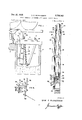
Figure 1 is a view in side elevation, partly in section and partly broken away, showing the turner in its forward position at a point beneath the skidway.
Figure 2 is a view similar to Figure l, the full lines illustrating the nigger bar at its position below the skidway, the broken lines showing the nigger bar moving vertically out of the hole.
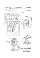
tes Patent proper saw line for making Figure 3 is a fragmental view in perspective illustrating the component parts of the movable stop element.
Figure 4 is a vertical sectional view taken along the line 4-4 of Figure 5, the view looking in the direction of the arrows.
Figure 5 is a horizontal line 55 of Figure 4.
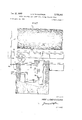
Figure 6 (sheet 1) is a view in perspective and partly broken away of the control lever for operating the valve assembly controlling the fluid circuit to the cylinder and also for operating the movable stop element, and
Figure 7 is a view in elevation, partly in cross section and partly broken away, of the cylinder and piston assembly.
In Figure 1, it will be noted that a log carriage 1 of conventional type moves along rails 2 provided on floor 3 of a sawmill, a concrete pit 4 is located alongside of the mill at a point beneath the floor, and log turner 5 is supported within the pit 4.
As shown in Figures 1 and 3, the log turner 5 is defined sectional view taken along the by a pair of spaced apart vertically disposed channel bars 6, the flanges of the bars facing each other, and the lower ends of the bars are secured to a base plate 7. A further channel bar 8 is similarly anchored at its lower end to the base plate 7 and extends upwardly from the base plate at an angle, as clearly indicated in Figures 1 and 2. The upper or free ends of the channel bars 6 and 8 are anchored to spaced apart angle irons 9 and at one end the irons 9 are connected together by a lateral support 10. The opposite ends of the angle irons 9 are welded to a transverse plate 11 provided with a stop plate 12 which overlies the gap between the spaced channel bars 6 at the front end thereof, and it will be appreciated that there is provided a vertically disposed slot or recess fromthe lower ends of the channel bars 6 to the plate 12. Additionally, a horizontal slot will extend between the angle irons 9, the angle iron 10 and the plate 11.
The nigger bar comprises two spaced parallel plates I 13, the lower ends of which are secured to a base 14, the perimeter of which conforms to the configuration of the channel bars and is spaced slightly inwardly of the inner face of the channel bars. The plate, of course, serves to prevent the nigger bar from leaving the frame, and also guiding the bar along the channel bars. Either integrally formed with the base 14 or made of a separate piece is a foot or extension 14A which is of such width as to extend through the slot between the flanges of the channel bars and project a short distance beyond the flanges. The upper ends of the plates 13 are secured together, and a plurality of pivoted teeth 15 are supported between the plates adjacent the upper ends thereof. A bumper is carried by the base 7 beneath the nigger bar and functions to absorb the shock imparted to the nigger bar when it strikes the base plate 7. To minimize shock, when the nigger bar is in the back position or the position under the skid, a resilient bumper 17 is attached in a removable manner to the vertical flange of the angle iron 10.
In order to move the nigger bar, it will be noted that a cylinder 18 is pivoted at its lower end to spaced lugs 19 by a removable bolt or the like 20. A piston rod 21 having a piston 22 at the lower end thereof is mounted within the cylinder, and the upper end of the cylinder carries a packing gland unit 23. The piston rod, that is to say the free end of the piston rod is pivoted as shown at 24 to spaced cars 25 welded to the plates 13 in proximity to the upper ends of the plates. The lower end of the cylinder is provided with a port 26 to which is secured a conduit section for admitting fluid into the lower end of the cylinder, a further port 27 is located near the upper end of the cylinder, and an elbow 28 is welded (3 to the outer surface of the cylinder, the elbow being in communication with the port. A tube 29 is fixed to the elbow and a second elbow 30 is carried by the lower end of the tube 29. A conduit is attached to the elbow 39. The conduit attached to the port 26 and the conduit secured to the elbow 39 lead to a four-way valve such as shown at 31 in Figure 6, the valve being operated by means of a lever 32 pivotally supported with respect to the valve. Hence, oil or other fluid may be supplied from a source of supply to the port 26 and the elbow 30 by proper manipulation of the lever 32. The valve 31 is similar to the valve assembly disclosed in my co-peuding application, Serial No. 227,627, filed May 22, 1951.
The piston 22 is of special construction and it will be noted that the lower end of the rod 21 is provided with a reduced extension 33 having an externally threaded portion 34. A bronze sleeve 35 is built up on the rod 21, and a leather or other composition cup 36 is fitted onto the end of the piston rod and is provided with a central opening for receiving the reduced extension 33. A bronze spacer 37 also surrounds the extension 33 and is in facial engagement with the base of the cup 36. A second cup 38 similar to the cup 36 is located on the extension 33 with the base thereof in contact with the opposite face of the spacer 37. A back-up washer 39 is placed within the cup 38 and a lock washer 40 is threaded onto the portion 34 of the extension 33 until it engages the washer 39. A castelated nut 41 is then drawn up on the threaded portion 34 and a cotter pin (not shown) may be inserted through the hole formed in the extension 33 at the outer end thereof for preventing any accidental displacement of the parts constituting the piston 22.
It will be appreciated, therefore, that there is little, if any, danger of the fluid leaking past the piston by virtue of the cup structure thereof and, in addition, since the extension projects downwardly beyond the cup 38, the extension will strike the bottom of the cylinder on the down stroke of the piston to function as a stop, and therefore, no shock will be directly imparted to the cup and, as a consequence, materially increase the life thereof. Furthermore, in the event it is necessary to replace either or both of the cups, this can be very easily accomplished by merely removing the nut 41 and the washers 39 and 40 which enables the lower cup 38 to drop off the extension 33. The upper cup 36 can also be quite easily removed.
The packing gland 23 comprises an annular ring 42 carried by the upper end of the cylinder barrel, and a plurality of packing rings or the like 43, preferably woven graphite packing, are supported by the ring 42. An internally threaded sleeve 44 is welded or otherwise attached to the cylinder barrel, and the upper end of the sleeve engages externally threaded portion 45 of a brass or bronze packing nut 46. By virtue of this assembly, there is little danger of leakage of fluid at the upper end of the cylinder and by applying a suitable tool to the nut 46, the packing gland can be disassembled and the rings 43 renewed if necessary.
As previously pointed out, the frame is provided with a movable stop element which is indicated generally 47, as shown in Figures 2 and 3. The stop element 47 comprises a pair of complemental brackets 43, each of which is welded along one side to the outer flanges of the channel bars 6. A stop 49 which is defined by a plate 50 having a hollow sleeve 51 at the upper end thereof is located between the brackets 48, with the ends of the hollow sleeve being adapted to be brought into registry with an opening 52 in each bracket 48. A lever arm 53 carries a rod 54 at one end thereof, the rod being disposed at right angles to the arm and has an outside diameter corresponding to the inside diameter of the hollow sleeve 51. The rod 54 is adapted to project through one of the openings 52 in the bracket 48 through the hollow sleeve 51, and the free end of the rod is journalled in the opening 52 of the other bracket 48. Set
The lever arm 53 is formed with a plurality of spaced openings 56, the desired opening being adapted to have one end of a cable 57 secured thereto, as shown at 58. The cable 57 passes over a pulley 59 which may be attached to one of the upper horizontal supports of the pit 4. The free end of the cable is attached to the lower end of the control lever 32, as shown at 60. The lever 32 projects through an elongated slot 61 formed in a horizontal support 62 which is bolted, as shown at 63, to the upper face of the control valve 31.
Needless to say, to prevent the plate 50 from moving too great a distance toward the nigger bar, it will be noted in Figures 4 and 5 that each of the brackets 48 is provided on the inner wall thereof with an abutment 64, preferably welded to the bracket. The abutment 64 is desirably in the form of a triangle with the hypotenuse thereof located so as to be engaged by the plate 50 as shown by the dotted line position of Figure 4. As mentioned above, when the lever 32 is in the neutral position, the weight of the plate 50 will move the plate to the full line position and therefore permit the nigger bar to move vertically past the plate.
On the other hand, when it is desired to move the plate into the path of travel of the nigger bar, the lever 32 which is in the neutral position, or at the opposite end of the slot shown in Fig. 6, is moved to the position illustrated in Fig. 6, thereby pulling the cable 57 which will move the plate 50 into engagement with the abutment 64 and maintain the plate in such position so long as the operator is holding the lever 32.
The operation of the turner may be briefly summarized as follows. With the nigger bar at its lower forward po sition such as shown in Figure 1, movement of the control lever 32 to admit fluid into the port 26 of the cylinder will raise the bar upwardly respecting the channel bars 6 to cause a log on the carriage 1 to be rotated by the teeth 15. By proper manipulation of the control lever 32, the nigger bar can be held at any desired position by the operator. If fluid is admitted into the upper port ofv the cylinder through the conduit 29, the bar can be moved to its back position in proximity to the channel bar 8, at which time the upper end of the bar will be below the deck or skidway, as perhaps more clearly shown in Figure 2 and the bar can be moved forwardly to roll or move the log from the skidway onto the carriage. It will be appreciated that by moving the plate 50 into engagement with the abutments 64, the plate 50 and the extension 14A will function as a fulcrum and greater power can be developed to force the log onto the carriage. In addition, the stop plate 12 and the extension 14A cooperate to provide a changeable fulcrum so that the higher the nigger bar is elevated, the greater the leverage against the log as thrust to turn or hold the log on the carriage is effected. Additionally, when the extension 14A engages the stop plate 12, the respective parts serve as means to limit the extent of upward vertical movement of the nigger bar. Consequently, when the nigger bar has been manipulated to move the log onto the carriage 1, the additional force which is developed by the stop members above described may also be employed to shove or move the blocks on the carriage rearwardly.
The lower end of the nigger bar has a sliding movement which provides a movable fulcrum permitting the bar to oscillate in and out as the log rolls over, applying pressure as the log rolls back against the head blocks, also holding the log in proper position for dogging and for stopping the log at the proper position for the next saw cut.
By virtue of the present invention, it is possible to use one cylinder for quickly and easily loading the logs onto the carriage, turning the log to the desired position for dogging, holding the log and moving the log back to the blocks, in addition to moving the blocks rearwardly respecting the carriage.
This invention is not to be confined to any strict conformity with the showing in the drawings but may be changed or modified so long as such changes or modifications mark no material departure from the salient features of the invention as expressed in the appended claims.
I claim:
1. A hydraulically operated log turner for sawmills including a frame fixedly anchored to the sawmill floor and extending downwardly with respect to the floor, a nigger bar slidably and oscillatably carried by the frame, a cylinder pivotally connected to the frame in spaced relation to the nigger bar, a pivotal connection between the piston rod in the cylinder and the nigger bar adjacent to the upper end of the bar, a source of hydraulic fluid, fluid lines leading from the fluid source to the cylinder, valve means interposed in the fluid lines for controlling the flow of fluid to and from the cylinder, control means for actuating the valve means, a stop plate supported by the frame adjacent the upper end thereof, a stop on the lower end of the nigger bar adapted to engage said stop plate during upward movement thereof to limit the extent of upward movement of the bar and also serve as a fulcrum for oscillating movement of the bar, a stop element pivotally mounted on the frame for movement about a horizontal axis intermediate the upper and lower ends of the frame, said stop element normally being located out of the path of the nigger bar, and control means operatively connected to said pivoted stop element to move the stop element about its pivot into the path of the nigger bar whereby on the upward movement of the nigger bar, the stop on the bar engages the said stop element to oscillate the nigger bar about the stop element as a fulcrum to move the log onto the carriage.
2. A log turner as defined in and claimed by claim 1 further characterized in that said stop element includes spaced brackets carried by the frame, a plate journalled between the brackets for movement about a horizontal axis, an abutment on at least one of the brackets to limit the movement of the plate toward the nigger bar, the means for moving the stop element being connected to the said plate.
3. A log turner as defined in and claimed by claim 2 further characterized in that the means for moving the stop element includes an arm rigidly supported by the plate, a cable attached to the arm, and means connecting the cable to the control means so that movement of the control means will move the plate against the abutment.
4. In a hydraulic log turner for sawmills, a pair of spaced horizontal angle irons, means secured to the front and rear ends of the angle irons to maintain the angle irons in spaced relationship to define a slot therebetween, further means for securing the angle irons above an opening in the sawmill floor, a pair of spaced downwardly exa cable connected to the arm,
tending channel bars aflixed to the angle irons adjacent the front ends of the angle irons with the flanges facing each other, a base plate secured to the channel bars, a brace secured to the base plate in spaced relation to the channel bars and extending upwardly from the base plate, means connecting the free end of the brace to the rear of the angle irons, a toothed nigger bar disposed between said channel bars, a guide on the nigger bar extending into the area defined by the flanges of the channel bars whereby the nigger bar may move relative to the channel bars, a cylinder pivotally connected to the base plate, a pivotal connection between the cylinder piston rod and the nigger bar adjacent the upper end of the nigger bar, a source of hydraulic fluid, fluid conduits leading from the fluid source to the cylinder, valve means interposed in the conduits to control the flow of fluid to and from the cylinder, a lever for actuating the valve means, a stop plate carried by the flanges of the channel bars at the upper end thereof and spanning the hiatus between the bar flanges, a stop on the nigger bar adjacent the lower end thereof extending between the flanges adapted to engage the stop plate during upward movement of the nigger bar to limit the extent of upward movement of the nigger bar and also serve as a fulcrum for oscillating movement of the nigger bar, a stop element pivotally mounted on said downwardly extending channel bars for movement about a horizontal axis intermediate the upper and lower ends of said channel bars, the stop element normally being located out of the path of the stop on the nigger bar, and control means operatively connected to the pivoted stop element to move the stop element about its pivot into the path of the nigger bar whereby on the upward movement of the nigger bar, the stop on such bar will engage the stop element to oscillate the nigger bar about the stop element as a fulcrum to move the log onto the carriage.
5. A log turner as defined in and claimed by claim 4 further characterized in that said stop element includes a bracket carried by a pair of the flanges of the channel bars, a plate is journalled betweenthe brackets for move ment about a horizontal axis, and an abutment is provided on at least one of the brackets to limit the movement of the plate toward the nigger bar.
6. A log turner as defined in andclaimed by claim 5 further characterized in that the means for moving the stop element includes an arm rigidly attached to the plate, and means connecting the cable to the lever so that movement of the lever will urge the plate against the abutment.
References Cited in the file of this patent UNITED STATES PATENTS 213,953 Tarrant Apr. 1, 1879 233,755 Hill Oct. 26, 1880 337,705 Rodgers Mar. 9, 1886 379,086 Torrent Mar. 6, 1888 2,574,974 Johnson Nov. 13, 1951
Priority Applications (1)
| Application Number | Priority Date | Filing Date | Title |
|---|---|---|---|
| US28295152 US2728362A (en) | 1952-04-18 | 1952-04-18 | Piston operated log turner with plural fulcrum stops |
Applications Claiming Priority (1)
| Application Number | Priority Date | Filing Date | Title |
|---|---|---|---|
| US28295152 US2728362A (en) | 1952-04-18 | 1952-04-18 | Piston operated log turner with plural fulcrum stops |
Publications (1)
| Publication Number | Publication Date |
|---|---|
| US2728362A true US2728362A (en) | 1955-12-27 |
Family
ID=23083840
Family Applications (1)
| Application Number | Title | Priority Date | Filing Date |
|---|---|---|---|
| US28295152 Expired - Lifetime US2728362A (en) | 1952-04-18 | 1952-04-18 | Piston operated log turner with plural fulcrum stops |
Country Status (1)
| Country | Link |
|---|---|
| US (1) | US2728362A (en) |
Citations (5)
| Publication number | Priority date | Publication date | Assignee | Title |
|---|---|---|---|---|
| US213953A (en) * | 1879-04-01 | Improvement in log-rollers | ||
| US233755A (en) * | 1880-10-26 | Eapids | ||
| US337705A (en) * | 1886-03-09 | Log-turner | ||
| US379086A (en) * | 1888-03-06 | Steam log-turner | ||
| US2574974A (en) * | 1946-05-16 | 1951-11-13 | Glen A Johnson | Portable sawmill |
-
1952
- 1952-04-18 US US28295152 patent/US2728362A/en not_active Expired - Lifetime
Patent Citations (5)
| Publication number | Priority date | Publication date | Assignee | Title |
|---|---|---|---|---|
| US213953A (en) * | 1879-04-01 | Improvement in log-rollers | ||
| US233755A (en) * | 1880-10-26 | Eapids | ||
| US337705A (en) * | 1886-03-09 | Log-turner | ||
| US379086A (en) * | 1888-03-06 | Steam log-turner | ||
| US2574974A (en) * | 1946-05-16 | 1951-11-13 | Glen A Johnson | Portable sawmill |
Similar Documents
| Publication | Publication Date | Title |
|---|---|---|
| US3026865A (en) | Stone cutter | |
| US2316760A (en) | Material collecting and loading apparatus | |
| US2718732A (en) | Snagging grinder | |
| US4423759A (en) | Electrically powered log splitter | |
| US2728362A (en) | Piston operated log turner with plural fulcrum stops | |
| US2406826A (en) | Scraper | |
| US2549236A (en) | Log bucking chain saw | |
| US3369490A (en) | Pumping apparatus | |
| DE69701300D1 (en) | Hydraulic supply system for log splitters | |
| CN219820028U (en) | Feeding mechanism of wood splitting machine | |
| US419287A (en) | Lock-gate and dam | |
| US3010595A (en) | Leveling attachment for a fork lift truck | |
| US623002A (en) | Gerald | |
| US2655186A (en) | Power-operated log turner with fulcrum stop | |
| US2655185A (en) | Single cylinder fluid-actuated log turner | |
| US379086A (en) | Steam log-turner | |
| US415315A (en) | Log-turner | |
| US2191826A (en) | Shears and the like | |
| US3426926A (en) | Hydraulic system for use with telescopic boom apparatus | |
| US2912037A (en) | Pressure-responsive overload release devices | |
| US1464769A (en) | Sawmill appliance | |
| US2577826A (en) | Operating mechanism for materialhandling machines | |
| US2708467A (en) | Log turner | |
| US1930014A (en) | Dogging device | |
| US2795301A (en) | Drilling rig safety brake |