US2727770A - Jet sander for vehicles - Google Patents
Jet sander for vehicles Download PDFInfo
- Publication number
- US2727770A US2727770A US248404A US24840451A US2727770A US 2727770 A US2727770 A US 2727770A US 248404 A US248404 A US 248404A US 24840451 A US24840451 A US 24840451A US 2727770 A US2727770 A US 2727770A
- Authority
- US
- United States
- Prior art keywords
- sand
- orifice
- tube
- conduit
- reservoir
- Prior art date
- Legal status (The legal status is an assumption and is not a legal conclusion. Google has not performed a legal analysis and makes no representation as to the accuracy of the status listed.)
- Expired - Lifetime
Links
- 239000004576 sand Substances 0.000 description 53
- 239000007789 gas Substances 0.000 description 19
- 239000004020 conductor Substances 0.000 description 5
- 230000015572 biosynthetic process Effects 0.000 description 2
- 230000001276 controlling effect Effects 0.000 description 2
- 238000007599 discharging Methods 0.000 description 2
- 239000000203 mixture Substances 0.000 description 2
- 230000001105 regulatory effect Effects 0.000 description 2
- 238000010276 construction Methods 0.000 description 1
- 239000000463 material Substances 0.000 description 1
- 239000002184 metal Substances 0.000 description 1
- 238000009987 spinning Methods 0.000 description 1
Images
Classifications
-
- B—PERFORMING OPERATIONS; TRANSPORTING
- B60—VEHICLES IN GENERAL
- B60B—VEHICLE WHEELS; CASTORS; AXLES FOR WHEELS OR CASTORS; INCREASING WHEEL ADHESION
- B60B39/00—Increasing wheel adhesion
- B60B39/02—Vehicle fittings for scattering or dispensing material in front of its wheels
- B60B39/04—Vehicle fittings for scattering or dispensing material in front of its wheels the material being granular, e.g. sand
Definitions
- Another object of this invention is the provision of means for sanding vehicle wheels in both forward and rearward movement thereof.
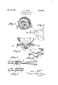
- Figure 1 is a perspective elevational view showing a vehicle wheel and two sand discharging conduits.
- Figure 2 is a sectional view showing a sand reservoir, an exhaust and sand conductor and an orifice used with my invention.
- Figure 3 is a sectional view taken on line 3--3 of Figure 2 and showing additional portions of the exhaust and sand conductor.
- Figure 4 is a side elevational view of the sand reservoir and exhaust conductor.
- Figure 5 is a bottom view of the exhaust and sand conductor.
- Figure 6 is a perspective View showing additional portions of the exhaust and sand conductor as it leads to the wheels or" a car.
- the jet sander comprises two units. One unit is provided for forward driving and sands in front of the wheelsnormally the rear wheels only. The other unit provides for backing up and will dispense sand to the rear of the wheels. Described herein is one unit only. The only difference in the two units is in the construction of the delivery or discharge portions of the units. The discharge pipes or portions of the unit used While backing must be extended to a point near the back of the wheels, whereas those of the forward unit must be extended to the front of the wheels.
- 10 represents a sand reservoir which is preferably made of metal, but which obviously can be made of other materials.
- the reservoir may be of a different size and shape which is suitable for the vehicle with which it is intended to be used.
- the reservoir has a base portion 11 provided with a depending outlet tube 12 forming a part thereof.
- the outlet tube changes in shape in running from top to bottom.
- the top portion 13 is generally cylindrical, whereas the bottom 14 thereof is oval shape (see Fig. 3). This results in the formation of a small orifice 15 at the bottom of the tube.
- the change from cylindrical to oval shape is gradual, resulting in a smooth inner surface in said outlet tube.
- an exhaust conduit 16 having a bulbous U-shaped portion 17, which encloses said tube 12.
- Said conduit is curved downwardly in the vicinity of the point of attachment and the bulbous portion thus depends from said tube.
- a cieanout plug 18 is provided and has threaded engagement at 19 with the bulbous portion of the conduit.
- the cleanout hole thus provided is directly in line with the tube 13 and at the bottom of the bulbous portion 16.
- the bulbous portion forms a cup-formation below said orifice for receiving sand therefrom. Said cuplike formation or portion extends above said orifice.
- the conduit 16 extends for a slight distance beyond the bulbous portion thereof then it is divided into two branch conduits 2t? and 21, respectively.
- Branch 20 is extended to one rear wheel while branch 21 is extended to the other rear wheel.
- the discharge or delivery portions of branches 20 and 21 are supported directly in front of the Wheel and in position to discharge sand so that it strikes the roadway directly in the line of the wheel tracks.
- the discharge or delivery portions are supported so that sand will strike the roadway directly in the path of the wheel. In both instances the sand will be cast in such a manner as to provide traction even if the vehicle is standing still and the wheels are merely spinning in place.
- FIG 6 and Figure 1 the branches for discharging the sand in the front and in the rear of the path of the wheel are shown.
- the conduit 16 divides into two branch conduits 20 and 21 respectively and conduit 2%) divides into branch conduits 2t) located at the rear of the wheel and 20" located at the front of the wheel.
- the other branch conduit 21 also divides into two branch conduits 21' to the rear of the wheel and 21" to the front of the wheel.
- valve arrangement At the forward end of conduit 16 a suitable valve arrangement not shown, is provided for diverting the flow of exhaust gases from the exhaust pipe to the conduit 16.
- the valve arrangement may comprise any one of the many known flow control devices used in the art, or any other suitable valving may be employed.
- the reservoir, the conduits and the valve mechanism may be supported in any convenient manner. There being no invention claimed therein, the support means are not shown. Only those elements necessary to disclose the invention are shown and described herein.
- the operation of the unit is as follows:
- the reservoir 10 is filled with sand.
- a small stream of sand will flow through the orifice 15 and deposit in the U-shaped bulbous portion 37.
- the sand will soon build up in the bulbous portion of the conduit to such an extent as to cut off further fiow of sand out of the reservoir.
- the exhaust valve is opened.
- the sand accumulated beneath the orifice is blown out of the bulbous portion through the two branches 20 and 21 'to the "wheels.
- the rate at which the sand is blown out will be proportional to the rate of flow and pressure of the exhaust gases in the conduit and consequently proportional to the valve opening.
- the speed of the engine and the load thereon varies and will atfect the quantity and pressure of gases available for sanding.
- a sanding device comprising a reservoir, an outlet tube therefor connectcd to the lower portion thereof and depending therefrom, said outlet tube comprising a generally cylindrical upper portion, said tube tapering downwardly and inwardly to a generally oval shaped lower portion, said tube having an orifice constituting the outlet therefrom, a gas and sand conduit extending generally horizontally below said reservoir and affixed thereto and to said tube, said conduit having a depending bulbous portion surrounding said tube and orifice providing channels on both sides of said tube and orifice, said bulbous portion forming a cup for receiving sand from said reservoir, said cup extending above said orifice through said bulbous portion having an opening therethrough below said tube and aligned therewith, a plug in said opening in threaded engagement with said conduit.
- a sander comprising a reservoir, a tube attached to and depending from said reservoir, a nozzle formed on the end of said tube and provided with an elliptical orifice, a conduit attached to said reservoir and having Thus it is seen that the maximum rate of,
- a depending bulbous portion surrounding said tube and said orifice providing channels on both sides of said tube and orifice, said bulbous portion forming a cup below said orifice and extending above said orifice.
- a sander comprising a reservoir, a tube attached to and depending from said reservoir, a nozzle formed on the end of said tube and provided with an elliptical orifice, a conduit attached to said reservoir and having a depending bulbous portion surrounding said tube and said orifice providing channels on both sides of said tube and orifice, said bulbous portion forming a cup below said orifice and extending above said orifice, said conduit serving to direct exhaust gases to said bulbous portion and through said channels and serving to direct a mixture of gases and sand from said cup to the wheels of a vehicle, said conduit having branches extending therefrom to said wheels.
- a jet sander for vehicles comprising a sand reservoir, an outlet tube formed at the base thereof, said outlet tube having a generally cylindrical upper portion and tapering downwardly to its end, said tube having an elliptical orifice in its lower end which forms an outlet for the sand, a conduit for exhaust gases from the vehicle, extending horizontally beneath said reservoir, a depending bulbous tubular sand trap formed in said conduit and having in general the shape of a V, said trap surrounding said outlet tube such that the end of said tube is adjacent the bottom of said bulbous portion, and means including a downwardly sloping upper wall in said sand trap and constituted of an upper portion of said conduit, for directing the blast of exhaust gases from said conduit downward at an angle, down onto and over only the surface of the sand in said trap whereby the density of the sand and gas mixture which is delivered from the trap is varied as the exhaust gas and motor speed varies.
- a jet sander for vehicles comprising a tubular sand reservoir having in general the shape of a V, a depending discharge tube formed at the base of said reservoir, an elliptical nozzle formed on the end of said discharge tube, a bulbous sand trap surrounding said discharge tube, an inlet conduit for exhaust gases from the ve hicle, supplying a gas blast to said trap, means including a downwardly sloping upper wall in said sand trap and constituted of an upper portion of said inlet conduit, for directing said gas blast down onto and over only the surface of the sand in said trap, an exhaust conduit for conveying the sand and gas stream away from said trap, said exhaust conduit extending from said trap toward the rear of the vehicle.
Landscapes
- Engineering & Computer Science (AREA)
- Mechanical Engineering (AREA)
- Nozzles (AREA)
Description
Dec. 20, 1955 H. c. DAVIS JET SANDER FOR VEHICLES Filed Sept. 26, 1951 R o m S mm D 0 Y R R A H BY M, 1+
ATTORNEYS United States Patent JET SANDER FOR VEHICLES Harry C. Davis, North Chelmsford, Mass. Application September 26, 1951, Serial No. 248,404
Claims. (Cl. 291-11) This invention relates to jet sander for vehicles.
It is an object of this invention to provide a sander having an orifice for controlling the fiow of sand together with a means for utilizing exhaust gases for distributing sand to the wheels of the vehicle.
Another object of this invention is the provision of means for sanding vehicle wheels in both forward and rearward movement thereof.
It is a further object of the invention to provide an efiicient compact inexpensive means for sanding vehicle wheels.
It is a further object of this invention to control the rate of discharge of a sander by controlling the volume of vehicle exhaust gases utilized by the sander, and to limit the maximum discharge by means of an orifice through which the maximum discharge flow is not affected by exhaust gas. v
These and other objects and advantages will become apparent from the following description and the accompanying drawing, in which:
Figure 1 is a perspective elevational view showing a vehicle wheel and two sand discharging conduits.
Figure 2 is a sectional view showing a sand reservoir, an exhaust and sand conductor and an orifice used with my invention.
Figure 3 is a sectional view taken on line 3--3 of Figure 2 and showing additional portions of the exhaust and sand conductor.
Figure 4 is a side elevational view of the sand reservoir and exhaust conductor.
Figure 5 is a bottom view of the exhaust and sand conductor.
Figure 6 is a perspective View showing additional portions of the exhaust and sand conductor as it leads to the wheels or" a car.
Similar reference characters in the several figures represent simiiar parts.
Sanders have been previously employed in vehicles. However, a problem existsin finding some way to accurately regulate the flow of sand to the vehicle wheels. Particularly the maximum flow has been found to be difiicult to regulate. Numerous devices have been produced in attempts to solve this difiiculty. In all previously known devices the sand flow is poorly regulated and erratic performance of the vehicle results. In my invention 1 have devised a sander which overcomes this major objection to prior automotive sanders. The flow of sand in my device is easily controlled, and the maximum flow of the same is definitely regulated. The means by which this is accomplished is extremely simple.
The jet sander comprises two units. One unit is provided for forward driving and sands in front of the wheelsnormally the rear wheels only. The other unit provides for backing up and will dispense sand to the rear of the wheels. Described herein is one unit only. The only difference in the two units is in the construction of the delivery or discharge portions of the units. The discharge pipes or portions of the unit used While backing must be extended to a point near the back of the wheels, whereas those of the forward unit must be extended to the front of the wheels.
Referring now to the drawing: 10 represents a sand reservoir which is preferably made of metal, but which obviously can be made of other materials. The reservoir may be of a different size and shape which is suitable for the vehicle with which it is intended to be used. The reservoir has a base portion 11 provided with a depending outlet tube 12 forming a part thereof. The outlet tube changes in shape in running from top to bottom. The top portion 13 is generally cylindrical, whereas the bottom 14 thereof is oval shape (see Fig. 3). This results in the formation of a small orifice 15 at the bottom of the tube. The change from cylindrical to oval shape is gradual, resulting in a smooth inner surface in said outlet tube.
Attached to the base portion and the tube 12 is an exhaust conduit 16 having a bulbous U-shaped portion 17, which encloses said tube 12. Said conduit is curved downwardly in the vicinity of the point of attachment and the bulbous portion thus depends from said tube. A cieanout plug 18 is provided and has threaded engagement at 19 with the bulbous portion of the conduit. The cleanout hole thus provided is directly in line with the tube 13 and at the bottom of the bulbous portion 16. The bulbous portion forms a cup-formation below said orifice for receiving sand therefrom. Said cuplike formation or portion extends above said orifice.
The conduit 16 extends for a slight distance beyond the bulbous portion thereof then it is divided into two branch conduits 2t? and 21, respectively. Branch 20 is extended to one rear wheel while branch 21 is extended to the other rear wheel. For the forward unit the discharge or delivery portions of branches 20 and 21 are supported directly in front of the Wheel and in position to discharge sand so that it strikes the roadway directly in the line of the wheel tracks. For the unit used when backing up the discharge or delivery portions are supported so that sand will strike the roadway directly in the path of the wheel. In both instances the sand will be cast in such a manner as to provide traction even if the vehicle is standing still and the wheels are merely spinning in place. In Figure 6 and Figure 1 the branches for discharging the sand in the front and in the rear of the path of the wheel are shown. The conduit 16, as above stated, divides into two branch conduits 20 and 21 respectively and conduit 2%) divides into branch conduits 2t) located at the rear of the wheel and 20" located at the front of the wheel. The other branch conduit 21 also divides into two branch conduits 21' to the rear of the wheel and 21" to the front of the wheel.
At the forward end of conduit 16 a suitable valve arrangement not shown, is provided for diverting the flow of exhaust gases from the exhaust pipe to the conduit 16. The valve arrangement may comprise any one of the many known flow control devices used in the art, or any other suitable valving may be employed. The reservoir, the conduits and the valve mechanism may be supported in any convenient manner. There being no invention claimed therein, the support means are not shown. Only those elements necessary to disclose the invention are shown and described herein.
The operation of the unit is as follows: The reservoir 10 is filled with sand. A small stream of sand will flow through the orifice 15 and deposit in the U-shaped bulbous portion 37. The sand will soon build up in the bulbous portion of the conduit to such an extent as to cut off further fiow of sand out of the reservoir. When sanding is desired the exhaust valve is opened. The sand accumulated beneath the orifice is blown out of the bulbous portion through the two branches 20 and 21 'to the "wheels. The rate at which the sand is blown out will be proportional to the rate of flow and pressure of the exhaust gases in the conduit and consequently proportional to the valve opening. Of course the speed of the engine and the load thereon varies and will atfect the quantity and pressure of gases available for sanding.
When the sand starts to be ejected out of the tube below the orifice, more reservoir sand will start to flow from the orifice. As stated above the quantity as well as the velocity of the sand ejected will be determined by the pressure and flow of the exhaust gases in the conduit, however, this is true only through a certain range of quantities. Sand flows through the orifice when sand is being blown out of the bulbous portion 17. As long as the rate of flow of sand to the wheels does not exceed the maximum possible rate of flow through the orifice, the rate of flow to the wheels is directly proportional to gas ilow. However, when the sand starts to be passed to the wheels at a rate greater than the maximum rate possible through the orifice the supply of sand in the bulbous portion 1'7 will start to be depleted, and the flow of sand out of the tube will now be governed by the rate of replacement of sand through the orifice. discharge of sand to the wheels is controlled by the size of orifice 14.
When the exhaust valve is closed sand will continue to deposit in the bulbous portion of tube 16 until the flow through the orifice is shut off by the deposited sand.
From the foregoing description of the present invention it will be seen that I have devised a sander for vehicles which is extremely simple yet provides a foolproof accurate means of limiting the maximum fiow of sand.
While I have shown and described a preferred form of my invention, it will be understood that variations in details of form may be made without departure from the invention as defined in the appended claims.
I claim:
1. A sanding device comprising a reservoir, an outlet tube therefor connectcd to the lower portion thereof and depending therefrom, said outlet tube comprising a generally cylindrical upper portion, said tube tapering downwardly and inwardly to a generally oval shaped lower portion, said tube having an orifice constituting the outlet therefrom, a gas and sand conduit extending generally horizontally below said reservoir and affixed thereto and to said tube, said conduit having a depending bulbous portion surrounding said tube and orifice providing channels on both sides of said tube and orifice, said bulbous portion forming a cup for receiving sand from said reservoir, said cup extending above said orifice through said bulbous portion having an opening therethrough below said tube and aligned therewith, a plug in said opening in threaded engagement with said conduit.
2. A sander comprising a reservoir, a tube attached to and depending from said reservoir, a nozzle formed on the end of said tube and provided with an elliptical orifice, a conduit attached to said reservoir and having Thus it is seen that the maximum rate of,
a depending bulbous portion surrounding said tube and said orifice providing channels on both sides of said tube and orifice, said bulbous portion forming a cup below said orifice and extending above said orifice.
3. A sander comprising a reservoir, a tube attached to and depending from said reservoir, a nozzle formed on the end of said tube and provided with an elliptical orifice, a conduit attached to said reservoir and having a depending bulbous portion surrounding said tube and said orifice providing channels on both sides of said tube and orifice, said bulbous portion forming a cup below said orifice and extending above said orifice, said conduit serving to direct exhaust gases to said bulbous portion and through said channels and serving to direct a mixture of gases and sand from said cup to the wheels of a vehicle, said conduit having branches extending therefrom to said wheels.
4. A jet sander for vehicles comprising a sand reservoir, an outlet tube formed at the base thereof, said outlet tube having a generally cylindrical upper portion and tapering downwardly to its end, said tube having an elliptical orifice in its lower end which forms an outlet for the sand, a conduit for exhaust gases from the vehicle, extending horizontally beneath said reservoir, a depending bulbous tubular sand trap formed in said conduit and having in general the shape of a V, said trap surrounding said outlet tube such that the end of said tube is adjacent the bottom of said bulbous portion, and means including a downwardly sloping upper wall in said sand trap and constituted of an upper portion of said conduit, for directing the blast of exhaust gases from said conduit downward at an angle, down onto and over only the surface of the sand in said trap whereby the density of the sand and gas mixture which is delivered from the trap is varied as the exhaust gas and motor speed varies.
5. A jet sander for vehicles comprising a tubular sand reservoir having in general the shape of a V, a depending discharge tube formed at the base of said reservoir, an elliptical nozzle formed on the end of said discharge tube, a bulbous sand trap surrounding said discharge tube, an inlet conduit for exhaust gases from the ve hicle, supplying a gas blast to said trap, means including a downwardly sloping upper wall in said sand trap and constituted of an upper portion of said inlet conduit, for directing said gas blast down onto and over only the surface of the sand in said trap, an exhaust conduit for conveying the sand and gas stream away from said trap, said exhaust conduit extending from said trap toward the rear of the vehicle.
References Cited in the file of this patent UNITED STATES PATENTS 947,652 Schwartz Ian. 25, 1910 953,228 Pratte Mar. 29, 1910 1,086,454 Johnson Feb. 10, 1914 1,424,412 Johnson Aug. 1, 1922 1,637,609 Gilmore Aug. 2, 1927 1,795,105 Buyck Mar. 3, 1931
Priority Applications (1)
| Application Number | Priority Date | Filing Date | Title |
|---|---|---|---|
| US248404A US2727770A (en) | 1951-09-26 | 1951-09-26 | Jet sander for vehicles |
Applications Claiming Priority (1)
| Application Number | Priority Date | Filing Date | Title |
|---|---|---|---|
| US248404A US2727770A (en) | 1951-09-26 | 1951-09-26 | Jet sander for vehicles |
Publications (1)
| Publication Number | Publication Date |
|---|---|
| US2727770A true US2727770A (en) | 1955-12-20 |
Family
ID=22938965
Family Applications (1)
| Application Number | Title | Priority Date | Filing Date |
|---|---|---|---|
| US248404A Expired - Lifetime US2727770A (en) | 1951-09-26 | 1951-09-26 | Jet sander for vehicles |
Country Status (1)
| Country | Link |
|---|---|
| US (1) | US2727770A (en) |
Cited By (5)
| Publication number | Priority date | Publication date | Assignee | Title |
|---|---|---|---|---|
| US2832619A (en) * | 1955-08-31 | 1958-04-29 | Frank P Davis | Traction unit |
| US3210109A (en) * | 1962-03-20 | 1965-10-05 | Soler Jose Llubera | Compressed air operated sandbox for locomotives |
| US4203423A (en) * | 1977-06-27 | 1980-05-20 | Sno-Go Inc. | Vehicle safety device |
| EP0025203A1 (en) * | 1979-09-08 | 1981-03-18 | SAPI-Drucklufttechnik GmbH. | Sprinkling device for road vehicles |
| RU2636546C2 (en) * | 2012-07-13 | 2017-11-23 | Роберт Бош Гмбх | Device for blank processing |
Citations (6)
| Publication number | Priority date | Publication date | Assignee | Title |
|---|---|---|---|---|
| US947652A (en) * | 1909-08-26 | 1910-01-25 | Fred G Schwartz | Track-sanding appliance. |
| US953228A (en) * | 1909-01-25 | 1910-03-29 | Crissey J Crews | Vacuum air-sander. |
| US1086454A (en) * | 1913-07-05 | 1914-02-10 | Oscar Johnson | Track-sanding apparatus. |
| US1424412A (en) * | 1914-10-24 | 1922-08-01 | Frank E Johnson | Automobile |
| US1637609A (en) * | 1926-12-15 | 1927-08-02 | Thomas S Gilmore | Pneumatic sander |
| US1795105A (en) * | 1929-02-28 | 1931-03-03 | Jules A Buyck | Mechanism for regulatably spreading sand or grit |
-
1951
- 1951-09-26 US US248404A patent/US2727770A/en not_active Expired - Lifetime
Patent Citations (6)
| Publication number | Priority date | Publication date | Assignee | Title |
|---|---|---|---|---|
| US953228A (en) * | 1909-01-25 | 1910-03-29 | Crissey J Crews | Vacuum air-sander. |
| US947652A (en) * | 1909-08-26 | 1910-01-25 | Fred G Schwartz | Track-sanding appliance. |
| US1086454A (en) * | 1913-07-05 | 1914-02-10 | Oscar Johnson | Track-sanding apparatus. |
| US1424412A (en) * | 1914-10-24 | 1922-08-01 | Frank E Johnson | Automobile |
| US1637609A (en) * | 1926-12-15 | 1927-08-02 | Thomas S Gilmore | Pneumatic sander |
| US1795105A (en) * | 1929-02-28 | 1931-03-03 | Jules A Buyck | Mechanism for regulatably spreading sand or grit |
Cited By (5)
| Publication number | Priority date | Publication date | Assignee | Title |
|---|---|---|---|---|
| US2832619A (en) * | 1955-08-31 | 1958-04-29 | Frank P Davis | Traction unit |
| US3210109A (en) * | 1962-03-20 | 1965-10-05 | Soler Jose Llubera | Compressed air operated sandbox for locomotives |
| US4203423A (en) * | 1977-06-27 | 1980-05-20 | Sno-Go Inc. | Vehicle safety device |
| EP0025203A1 (en) * | 1979-09-08 | 1981-03-18 | SAPI-Drucklufttechnik GmbH. | Sprinkling device for road vehicles |
| RU2636546C2 (en) * | 2012-07-13 | 2017-11-23 | Роберт Бош Гмбх | Device for blank processing |
Similar Documents
| Publication | Publication Date | Title |
|---|---|---|
| US4569160A (en) | Sand blasting apparatus with liquid aspiration control | |
| US2691923A (en) | Apparatus for making traffic strips, including means for dispensing glass spheres and other materials onto painted strips | |
| US2727770A (en) | Jet sander for vehicles | |
| US2673090A (en) | Highway marking machine | |
| US5580106A (en) | Traction device | |
| US4968069A (en) | Sand dispensing device having plural compartments | |
| US2606781A (en) | Sand pipe dispensing nozzle | |
| US2451878A (en) | Sanding nozzle | |
| US2847318A (en) | Method and apparatus for resurfacing roofs | |
| US1795105A (en) | Mechanism for regulatably spreading sand or grit | |
| US2641476A (en) | Apparatus for dispensing small articles over a restricted area | |
| US1876610A (en) | Spray gun | |
| US2623766A (en) | Sander for motor vehicles | |
| US2207169A (en) | Sander for vehicle wheels | |
| US1797898A (en) | Sanding apparatus | |
| US1842506A (en) | Automobile skid preventing device | |
| US682150A (en) | Track-sander. | |
| US2710229A (en) | Spray nozzle | |
| US1516211A (en) | Antiskid device for automobiles and other vehicles | |
| GB1591900A (en) | Track sanding method and device | |
| US2154340A (en) | Traction attachment for vehicles | |
| US2797946A (en) | Rail sanding pipe | |
| US2878025A (en) | Highway marking apparatus | |
| US746116A (en) | Wheel guard and sander. | |
| US773909A (en) | Track-sander. |