US2697993A - Zigzag attachment for sewing machines - Google Patents
Zigzag attachment for sewing machines Download PDFInfo
- Publication number
- US2697993A US2697993A US259631A US25963151A US2697993A US 2697993 A US2697993 A US 2697993A US 259631 A US259631 A US 259631A US 25963151 A US25963151 A US 25963151A US 2697993 A US2697993 A US 2697993A
- Authority
- US
- United States
- Prior art keywords
- ratchet
- ratchet wheel
- pawl
- zig
- frame
- Prior art date
- Legal status (The legal status is an assumption and is not a legal conclusion. Google has not performed a legal analysis and makes no representation as to the accuracy of the status listed.)
- Expired - Lifetime
Links
- 238000009958 sewing Methods 0.000 title description 16
- 210000003813 thumb Anatomy 0.000 description 6
- 238000010276 construction Methods 0.000 description 3
- 230000010355 oscillation Effects 0.000 description 2
- 230000002093 peripheral effect Effects 0.000 description 2
- 230000000694 effects Effects 0.000 description 1
Images
Classifications
-
- D—TEXTILES; PAPER
- D05—SEWING; EMBROIDERING; TUFTING
- D05B—SEWING
- D05B21/00—Sewing machines with devices for automatically controlling movement of work-carrier relative to stitch-forming mechanism in order to obtain particular configuration of seam, e.g. programme-controlled for sewing collars, for attaching pockets
- D05B21/002—Sewing machines with devices for automatically controlling movement of work-carrier relative to stitch-forming mechanism in order to obtain particular configuration of seam, e.g. programme-controlled for sewing collars, for attaching pockets consisting of lateral displacement of the workpieces by a feed-dog or a fluted presser foot
-
- D—TEXTILES; PAPER
- D05—SEWING; EMBROIDERING; TUFTING
- D05D—INDEXING SCHEME ASSOCIATED WITH SUBCLASSES D05B AND D05C, RELATING TO SEWING, EMBROIDERING AND TUFTING
- D05D2303/00—Applied objects or articles
- D05D2303/02—Tape
Definitions
- ZIGZAG ATTACHMENT FOR SEWING MACHINES will ml' l/ Filed Deo. 3, 1951 2 Sheets-Sheet 2 uumlrl l um! 595 1.7mm 2 5, 62 2 I8 2O 'y I y EW) I7 64 INVENTOR.
- My invention relates to improvements on zig zag at tachments for sewing machines, and is particularly adapted to be used in connection with the lock stitch type sewing machine.
- the primary object of my invention is to provide an attachment on zig zaggers so that the zig zagger can sew a blind hem stitch.
- Another object of my invention is to design an upper transverse feed dog associated with the presser bar, wherein the tension on the thread need not be altered in the sewing operation in order to prevent puckering of the material.
- Figure l is a side view of a conventional zig zag atta-chment mounted to the presser bar of a sewing ma-4 chine and associated with the needle bar, the rest of the sewing machine being broken away.
- Figure 2 is a plan View of the zig zagger, taken on line 2-2 of Figure 1.
- Figure 3 is a fragmentary side View of the zig zagger, the driving pawl being disconnected from the driven ratchet wheel of the zig zagger bymy idler ratchet wheel attachment, parts broken away for convenience of illustration.
- Figure 4 is an exploded perspective View of the cam driving ratchet wheel of the zig zagger and my new and v improved i-d-ler ratchet wheel for causing intermittent rotation of the zig zagger ratchet wheel.
- Figure 5 is a side view of the zig zagger similar to Figure 3, parts broken away illustrating the driving pawl engaged with the ratchet wheel of the zig zagger for rotating the same.
- Figure 6 is an end sectional view, taken on line 6--6 of Figure l, illustrating the driving pawl engaging the driven ratchet wheel.
- Figure 7 is a fragmentary sectional view, taken through the zig zagger, particularly illustrating the operation of the cam for oscillating the presser foot.
- Figure 8 is a sample of stitching, illustrating the stitch heretofore made by the zig zagger and the blind hem stitch that my new and improved attachment will cause the zig zagger to stitch.
- Figure 9 is an enlarged fragmentary sectional side view of my new and improved presser foot assembly.
- Figure 10 is an inverted plan view, taken on line 10-10 of Figure 9.
- Figure 11 is a fragmentary side View of anotherpreferred form of material feeder guide construction.
- FIG. 12 is a fragmentary detail sectional view, illustrating how my idling ratchet wheel uncovers the ratchet wheel of the zig zagger.
- a conventional zig zagging attachment is indicated in general by numeral 1, attached to the presser bar 2 of the sewing machine. I will first describe the general construction of the zig zagger and its operation.
- the zig zagger consists of a U-shaped frame 3. 4A shank 4 is connected to the frame 3 by the cross pins 5, the said shank adapted to be connected to the lower end of the presser bar 2 and locked thereon by the set screw 6. A shaft 7 is journalled within the 'bearings 8 of the upwardly extending side walls 9 of the U-shaped frame 3, referring to Figure 6,
- a cam 2,697,993 Patented Dec. 28, 1954 ICC i 10 which is xedly secured to the shaft by the set screw 11.
- Rotatably mounted on Athe shaft 7 is the fork arm 12, Figures 1, 2, 3 and 5, whose forked end 13 engages the needle locking set screw 14 of the reciprocating needle bar 15 in the usual manner.
- Fixedly secured to the corrugated portion 16 of the shaft 7 is the usual ratchet wheel 17.
- the usual operating pawl 18 is pivotally connected to the fork arm 12 at 19, and is adapted to have its tip 20 engage lthe ratchet teeth 21 of the ratchet wheel 17, as best illustrated in Figures 5 and 6.
- the operation of the cam 10 will be more fully described later on.
- the presser foot assembly 22 will now be described.
- the presser foot assembly consists of a horizontal bar 23, which is pivotally mounted to the frame 3 of the zig zagger in the following manner.
- the 'bar 23 is movably mounted between the base 24 of the frame 3 and the base 25 of the sub-frame 26.
- a pivot pin 27 is ixedly secured to the base 25 of the sub-frame 26. This provides a pivot point for the bar 23.
- the sub-frame 26 is adapted to be moved longitudinally of the frame 3 and locked in any desired position by the locking shoulder bolt 28, referring to Figure 6, the shoulder 29 of the bolt 28 engaging the side wall 30 of the sub-frame 26 on 'being threaded into the side of the frame 3.
- the sub-frame 26 is secured to the base 24 of the frame 3 by the shoulder pin 31, which is ixedly secured to the base 24 by passing through the slot 32 of the sub-frame 26, securing the said frame to the base 24 of the frame 3 by permitting longitudinal movement of the frame 26 by way of the slot 32 and the slots 33 and 34 formed in the base 24 of the frame 3, and in the bar 23 of the presser foot assembly Z2.
- the inner end 35 of the 'bar 23 has a cam follower 36 iiXedly secured thereto as at 37.
- the said follower 36 extends upwardly from the bar 23 through a transverse slot 38 formed in the base 24 of the frame 3.
- cam roller 39 cooperates with the cam surfaces 40 formed around the periphery of the cam 10. As the cam is revolved it will oscillate the bar 23 transversely of the frame 3 about the pivot shaft 27, together with the presser foot 41 and the slotted material guide 42.
- the sub-frame 26 is moved longitudinally jof the frame 3.
- the pivot pin 27 moves with the frame 26 through the slot 33 of the base 24 and the slot 34 of the bar 23.
- the further away the position of the pivot shaft 27 is in relation to the cam follower shaft 36 the lesser will lbe the transverse stroke of the presser foot asis known as a blind hem stitch.
- the needle bar 15 is permittedto travel up and down a predetermined number of stitches without the transverse movement of the presser foot.l After a predetermined number of stitches are made, as
- I rotatably mount an idler ratchet wheel 48 to the shaft 7 at 49, Figure 6.
- This ratchet wheel has its ratchet teeth 50 formed on a flange 51.
- Thumb nut 55 is threaded on to the shaft 7 by way of the threads 56, and is adapted to maintain the ratchet wheel 48 in the position illustrated in Figure 6.
- the ange 51 of the wheel overlaps or embraces the periphery ofthey ratchet wheel 17. It is desirable not to force the nut 55 against the ratchet wheel 48, but against the shoulder 7A of the shaft 7, permitting the ratchet wheel to revolve freely on the shaft at all times.
- a coil spring 57 bears against the inner wall 58 of the ratchet wheelV 48 and against the face of the ratchet 17.
- the object of this spring is to force the ratchet wheel 48 away from the ratchet 17 uncovering its periphery when the thumb nut 55 is backed off, referring to Figure l2.
- This spring 57 also provides sufficient friction between the idler ratchet and the shaft 7 to prevent backward movement of the said ratchet wheel when the pawl 18 is receded by the operation of the forked arm 12.
- My ⁇ invention further consists of removing a portion of ther flange of the idler ratchet wheel, as indicated at S9 and 60.
- I illustrate the pawl passing through the opening 59 and engaging the ratchet teeth 21 of the ratchet wheel 17, thereby rotating the cam wheel 10. In the position shown this would be returning the presser bar assembly to its straight line sewing 47, after making the stitch 61.
- the pawl will ride on the ratchet teeth 50 of the idler ratchetwheel 48, as best illustrated in Figure 3, permitting the ratchet wheel 17 to remain stationary thereby permitting the presser foot assembly 22 to remain stationary on the sewing line 47, also until the point 2.0v of the pawl 18 will drop into the opening 60 of the idler ratchet wheel 48 engaging one of the ratchet teeth 21 of the ratchet wheel 17. This will rotate the cam so as to move the cam follower 36, together with the end of the bar 23, pivoting the same about the pivot pin 27 moving the presser foot assembly either to the right or left, making the stitch 61.
- the cam lobe selected will determine the position of the presser foot and guide 42, either to the right or left of the line of sewing. Then naturally this position will determine the direction that the olf-set ⁇ stitch will be made when the cam is moved by the ratchet wheel 17.
- the thumb nut 5S is backed ofl", permitting the spring 57 to move the idler camV 48 along the shaft 7 a sufficient distance to permit the pawl 18 to engage th'e teeth of the ratchet wheel 17 ony each oscillation ofthe needle bar 15;
- V-cut-outs 41A on the rear of the foot 41 that the material is slightly stabilized while being moved under the foot by the feed mechanism.
- a zig-zag sewing machine mechanism having a presser foot adapted to be swung laterally by a cam fixed on a shaft with a drive ratchet which is engaged by a pawl that is operated by the needle bar
- the improvement comprising an idler ratchet journaled on said ⁇ shaft beside said' drive ratchet and slidable thereon relative to said drive ratchet for movement between positions within and beyond the stroke of said pawl, said idler ratchet including a peripheral toothed iiange extending over the ydrive ratchet to engage said pawl and thereby prevent engagement of said drive ratchet by said pawl, said flange having at least one area in its periphery between adjacent teeth open to permit said pawl to periodically engage said drive ratchet.
Landscapes
- Engineering & Computer Science (AREA)
- Textile Engineering (AREA)
- Sewing Machines And Sewing (AREA)
Description
Dec. 28, 1954 c. A. RoLFsoN 2,697,993
zrczAG ATTACHMENT FOR SEWING MACHINES Filed Deo. 3, 1951 2 Shee'ts-Sheet 1 'milf ump lllllh -im mgm 4f INVENTOR.
. ROLFSON AT TORNEY Dec. 28, 1954 l c. A. RoLFsoN 2,597,993
ZIGZAG ATTACHMENT FOR SEWING MACHINES will ml' l/ Filed Deo. 3, 1951 2 Sheets-Sheet 2 uumlrl l um! 595 1.7mm 2 5, 62 2 I8 2O 'y I y EW) I7 64 INVENTOR. CORNEUUS A. ROlTFSON BY 5 l ATTORNEY United States Patent O P ZIGZAG ATTACHMENT FOR SEWING MACHINES y Cornelius A. Rolfson, Portland, Oreg.
Application December 3, 1951, Serial No. 259,631
Claims. (Cl. 112-160) My invention relates to improvements on zig zag at tachments for sewing machines, and is particularly adapted to be used in connection with the lock stitch type sewing machine.
The primary object of my invention is to provide an attachment on zig zaggers so that the zig zagger can sew a blind hem stitch.
Another object of my invention is to design an upper transverse feed dog associated with the presser bar, wherein the tension on the thread need not be altered in the sewing operation in order to prevent puckering of the material.
These and other incidental objects will be apparent in the drawings, specication and claims.
Referring tothe drawings:
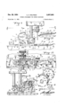
Figure l is a side view of a conventional zig zag atta-chment mounted to the presser bar of a sewing ma-4 chine and associated with the needle bar, the rest of the sewing machine being broken away.
Figure 2 is a plan View of the zig zagger, taken on line 2-2 of Figure 1.
Figure 3 is a fragmentary side View of the zig zagger, the driving pawl being disconnected from the driven ratchet wheel of the zig zagger bymy idler ratchet wheel attachment, parts broken away for convenience of illustration.
Figure 4 is an exploded perspective View of the cam driving ratchet wheel of the zig zagger and my new and v improved i-d-ler ratchet wheel for causing intermittent rotation of the zig zagger ratchet wheel.
Figure 5 is a side view of the zig zagger similar to Figure 3, parts broken away illustrating the driving pawl engaged with the ratchet wheel of the zig zagger for rotating the same.
Figure 6 is an end sectional view, taken on line 6--6 of Figure l, illustrating the driving pawl engaging the driven ratchet wheel.
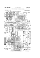
Figure 7 is a fragmentary sectional view, taken through the zig zagger, particularly illustrating the operation of the cam for oscillating the presser foot.
Figure 8 is a sample of stitching, illustrating the stitch heretofore made by the zig zagger and the blind hem stitch that my new and improved attachment will cause the zig zagger to stitch.
Figure 9 is an enlarged fragmentary sectional side view of my new and improved presser foot assembly.
Figure 10 is an inverted plan view, taken on line 10-10 of Figure 9.
Figure 11 is a fragmentary side View of anotherpreferred form of material feeder guide construction.
-Figure 12 is a fragmentary detail sectional view, illustrating how my idling ratchet wheel uncovers the ratchet wheel of the zig zagger.
Referring more specifically to the drawings:
A conventional zig zagging attachment is indicated in general by numeral 1, attached to the presser bar 2 of the sewing machine. I will first describe the general construction of the zig zagger and its operation.
The zig zagger consists of a U-shaped frame 3. 4A shank 4 is connected to the frame 3 by the cross pins 5, the said shank adapted to be connected to the lower end of the presser bar 2 and locked thereon by the set screw 6. A shaft 7 is journalled within the 'bearings 8 of the upwardly extending side walls 9 of the U-shaped frame 3, referring to Figure 6,
Mounted on the shaft 7 within the frame 3, is a cam 2,697,993 Patented Dec. 28, 1954 ICC i 10 which is xedly secured to the shaft by the set screw 11. Rotatably mounted on Athe shaft 7 is the fork arm 12, Figures 1, 2, 3 and 5, whose forked end 13 engages the needle locking set screw 14 of the reciprocating needle bar 15 in the usual manner. Fixedly secured to the corrugated portion 16 of the shaft 7 is the usual ratchet wheel 17. The usual operating pawl 18 is pivotally connected to the fork arm 12 at 19, and is adapted to have its tip 20 engage lthe ratchet teeth 21 of the ratchet wheel 17, as best illustrated in Figures 5 and 6. As the needle bar raises and lowers, it revolves the cam 10 by the action of the pawl 18 through the ratchet wheel 17 i the distance of one ratchet tooth at a time. The operation of the cam 10 will be more fully described later on.
The presser foot assembly 22 will now be described. The presser foot assembly consists of a horizontal bar 23, which is pivotally mounted to the frame 3 of the zig zagger in the following manner. The 'bar 23 is movably mounted between the base 24 of the frame 3 and the base 25 of the sub-frame 26. A pivot pin 27 is ixedly secured to the base 25 of the sub-frame 26. This provides a pivot point for the bar 23.
The sub-frame 26 is adapted to be moved longitudinally of the frame 3 and locked in any desired position by the locking shoulder bolt 28, referring to Figure 6, the shoulder 29 of the bolt 28 engaging the side wall 30 of the sub-frame 26 on 'being threaded into the side of the frame 3. The sub-frame 26 is secured to the base 24 of the frame 3 by the shoulder pin 31, which is ixedly secured to the base 24 by passing through the slot 32 of the sub-frame 26, securing the said frame to the base 24 of the frame 3 by permitting longitudinal movement of the frame 26 by way of the slot 32 and the slots 33 and 34 formed in the base 24 of the frame 3, and in the bar 23 of the presser foot assembly Z2.
The inner end 35 of the 'bar 23 has a cam follower 36 iiXedly secured thereto as at 37. The said follower 36 extends upwardly from the bar 23 through a transverse slot 38 formed in the base 24 of the frame 3. A
cam roller 39 cooperates with the cam surfaces 40 formed around the periphery of the cam 10. As the cam is revolved it will oscillate the bar 23 transversely of the frame 3 about the pivot shaft 27, together with the presser foot 41 and the slotted material guide 42.
In order to change this transverse stroke of the presser foot assembly, the sub-frame 26 is moved longitudinally jof the frame 3. The pivot pin 27 moves with the frame 26 through the slot 33 of the base 24 and the slot 34 of the bar 23. The further away the position of the pivot shaft 27 is in relation to the cam follower shaft 36 the lesser will lbe the transverse stroke of the presser foot asis known as a blind hem stitch. In order to make the zig t zagger cause this stitch, the needle bar 15 is permittedto travel up and down a predetermined number of stitches without the transverse movement of the presser foot.l After a predetermined number of stitches are made, as
:indicated at 47 Figure 8, it is desirable to move the presser foot assembly transversely either to the right and back tothe straight line 47 or to the left and back to the This is accomplished by permit- -t1ng the pawl 18 to engage the ratchet teeth 21 of the straight line position.
ratyche't wheel 17 at predetermined points around the said ratchet wheel. I have illustrated this to happen twice in the circumference of the ratchet wheel.
In order to accomplish this, I rotatably mount an idler ratchet wheel 48 to the shaft 7 at 49, Figure 6. This ratchet wheel has its ratchet teeth 50 formed on a flange 51. Thumb nut 55 is threaded on to the shaft 7 by way of the threads 56, and is adapted to maintain the ratchet wheel 48 in the position illustrated in Figure 6. The ange 51 of the wheel overlaps or embraces the periphery ofthey ratchet wheel 17. It is desirable not to force the nut 55 against the ratchet wheel 48, but against the shoulder 7A of the shaft 7, permitting the ratchet wheel to revolve freely on the shaft at all times.
A coil spring 57 bears against the inner wall 58 of the ratchet wheelV 48 and against the face of the ratchet 17. The object of this spring is to force the ratchet wheel 48 away from the ratchet 17 uncovering its periphery when the thumb nut 55 is backed off, referring to Figure l2. This spring 57 also provides sufficient friction between the idler ratchet and the shaft 7 to prevent backward movement of the said ratchet wheel when the pawl 18 is receded by the operation of the forked arm 12.
My` invention further consists of removing a portion of ther flange of the idler ratchet wheel, as indicated at S9 and 60. Referring to Figures 2, 5 and 6, I illustrate the pawl passing through the opening 59 and engaging the ratchet teeth 21 of the ratchet wheel 17, thereby rotating the cam wheel 10. In the position shown this would be returning the presser bar assembly to its straight line sewing 47, after making the stitch 61.
On further operation of the form arm 12 and the pawl 8, the pawl will ride on the ratchet teeth 50 of the idler ratchetwheel 48, as best illustrated in Figure 3, permitting the ratchet wheel 17 to remain stationary thereby permitting the presser foot assembly 22 to remain stationary on the sewing line 47, also until the point 2.0v of the pawl 18 will drop into the opening 60 of the idler ratchet wheel 48 engaging one of the ratchet teeth 21 of the ratchet wheel 17. This will rotate the cam so as to move the cam follower 36, together with the end of the bar 23, pivoting the same about the pivot pin 27 moving the presser foot assembly either to the right or left, making the stitch 61.
There could be any number of openings 59 and 60 around the idler ratchet 48, but I have illustrated only two openings which will make ten straight stitches 47 with one offset stitch 61 with the number of ratchet teeth 50 that I illustrate in the drawings.
When the pawl 18 engages the ratchet teeth 21 of the ratchet wheel 17 through the openings 59 and 6i) for the distance of two ratchets completing the off-set stitch 61, means must be provided for maintaining the idler ratchet 48 in timed relation to the cam 17. This is accomplished by the ratchet tooth or cog 63 which rides in front of the pawl 18 at 64, moving the said idler ratchet wheel with the movement of the pawl and the ratchet wheel 17. This is an important feature in the maintaining ofthe timing of the device.
In order to determine which way the presser foot assembly will move, either to the right or left transverse ofthe line of stitching 47, I have extended the shaft 7 beyond the thumb nut and keyed the same to the thumb nut 62 so that by rotating the shaft 7 the distance of one ratchet tooth, it will position the lobes of the cam 10 in regards to the cam roller 39, positioning the presser foot assembly and guide 42 in a position to stitch in a straight line. Then when a further movement of the cam takes place it will move the presser foot assembly in the desired direction transversely of the line of sewing.
In other words, the cam lobe selected will determine the position of the presser foot and guide 42, either to the right or left of the line of sewing. Then naturally this position will determine the direction that the olf-set` stitch will be made when the cam is moved by the ratchet wheel 17. In the event that I wishtok stitch as indicated at 43 and 44, the thumb nut 5S is backed ofl", permitting the spring 57 to move the idler camV 48 along the shaft 7 a sufficient distance to permit the pawl 18 to engage th'e teeth of the ratchet wheel 17 ony each oscillation ofthe needle bar 15;
I will now describe my improvement inl the presser foot. assembly. Heretofore the face 65 ofthe presser foot'. had grooves o'r teeth running longitudinally of the line of stitching. As the presser foot assembly was osc1llated in the zig zag stitching it caused the material being sewed to pucker until the tension on the thread was' adjusted to the type of material being sewed. With my new and improvedpresser foot and guide 42, I mount a ilat spring 66 to the forward end of the guide 42 at 67. Teeth 68 are formed in the end of the spring as illustrated, particularly in Figure 2.
When the presser foot and guide 42 are oscillated from side to side in regards to the center line of the sewing, the downward pressure of the spring 66 at the point ot its teeth 68 will cause a tension on the material between the underside of the presser foot 41 and the said spring, preventing the material from puckering in the sewing operation. This spring provides a constant even pressure on the material being sewed, regardless of the thickness of material.
In the use of my new and improved construction of the presser foot assembly, I remove the horizontal feed perforations from under the foot so that the foot will have no effect in its oscillation in moving the material, only to maintain a pressure on the same while the teeth on the spring 66 move the material from side to side in regards to the needle, the foot only being employed to place a tension on the material between the said foot and the tip of the pressure spring 66. This smooths out the material, preventing puckering of the same while the material is being sewed.
I have found that by forming V-cut-outs 41A on the rear of the foot 41 that the material is slightly stabilized while being moved under the foot by the feed mechanism.
Referring to Figure l1, I have added an additional ilat spring 69 under the spring 66, the material 70 passing therebetween. This also provides an ideal feeding guide forr guiding the material into the path of the needle.
What I claim is:
l. In a zig-zag sewing machine mechanism having a presser foot adapted to be swung laterally by a cam fixed on a shaft with a drive ratchet which is engaged by a pawl that is operated by the needle bar, the improvement comprising an idler ratchet journaled on said `shaft beside said' drive ratchet and slidable thereon relative to said drive ratchet for movement between positions within and beyond the stroke of said pawl, said idler ratchet including a peripheral toothed iiange extending over the ydrive ratchet to engage said pawl and thereby prevent engagement of said drive ratchet by said pawl, said flange having at least one area in its periphery between adjacent teeth open to permit said pawl to periodically engage said drive ratchet.
2. Mechanism as defined in claim l wherein said presser foot has a forwardly extending guide, and a liat spring securedv to the forward end of said guide and extending back toward said foot to engage the material slightly in advance of said foot, the end of said spring being serrated, whereby the material being sewed is bodily shifted laterally by said spring and foot.
3. Mechanism as defined in claim 1 wherein said presser foot has a smooth material engaging surface provided with V-shaped notches in its trailing edge.
4. Mechanism as defined in claim 1 wherein said idler ratchet is resiliently biased from said drive ratchet beyoud engagement by said pawl, and a thumb nut threaded on said shaft toy move said idler ratchet into engagement with said pawl.
5. Mechanism as defined in claim l wherein said peripheral toothed flange of said idler ratchet is cylindrical in form and of a diameter for surrounding said drive ratchet.
References Cited in the file of this patent UNITED STATES PATENTS Number Name Date 1,261,192 Van Berkel Apr. 2, 1918 2,374,721 Bacon et al. May 1, 1945 2,553,514 Enos May 15, i
FOREIGN PATENTS Number Country Date 632,399 Germany July 7, 1936
Priority Applications (1)
| Application Number | Priority Date | Filing Date | Title |
|---|---|---|---|
| US259631A US2697993A (en) | 1951-12-03 | 1951-12-03 | Zigzag attachment for sewing machines |
Applications Claiming Priority (1)
| Application Number | Priority Date | Filing Date | Title |
|---|---|---|---|
| US259631A US2697993A (en) | 1951-12-03 | 1951-12-03 | Zigzag attachment for sewing machines |
Publications (1)
| Publication Number | Publication Date |
|---|---|
| US2697993A true US2697993A (en) | 1954-12-28 |
Family
ID=22985713
Family Applications (1)
| Application Number | Title | Priority Date | Filing Date |
|---|---|---|---|
| US259631A Expired - Lifetime US2697993A (en) | 1951-12-03 | 1951-12-03 | Zigzag attachment for sewing machines |
Country Status (1)
| Country | Link |
|---|---|
| US (1) | US2697993A (en) |
Cited By (2)
| Publication number | Priority date | Publication date | Assignee | Title |
|---|---|---|---|---|
| US2825295A (en) * | 1956-01-13 | 1958-03-04 | Greist Mfg Co | Decorative stitch attachments |
| US2983238A (en) * | 1955-12-19 | 1961-05-09 | Fremaco International Inc | Attachment for sewing machines |
Citations (4)
| Publication number | Priority date | Publication date | Assignee | Title |
|---|---|---|---|---|
| US1261192A (en) * | 1917-12-31 | 1918-04-02 | Us Slicing Machine Co | Ratchet mechanism. |
| DE632399C (en) * | 1935-04-13 | 1936-07-07 | Wuerker G M B H | Decorative stitching machine with gear mechanism for sewing machines |
| US2374721A (en) * | 1940-10-02 | 1945-05-01 | Greist Mfg Co | Sewing machine attachment |
| US2553514A (en) * | 1949-08-26 | 1951-05-15 | Singer Mfg Co | Hemstitching attachment for sewing machines |
-
1951
- 1951-12-03 US US259631A patent/US2697993A/en not_active Expired - Lifetime
Patent Citations (4)
| Publication number | Priority date | Publication date | Assignee | Title |
|---|---|---|---|---|
| US1261192A (en) * | 1917-12-31 | 1918-04-02 | Us Slicing Machine Co | Ratchet mechanism. |
| DE632399C (en) * | 1935-04-13 | 1936-07-07 | Wuerker G M B H | Decorative stitching machine with gear mechanism for sewing machines |
| US2374721A (en) * | 1940-10-02 | 1945-05-01 | Greist Mfg Co | Sewing machine attachment |
| US2553514A (en) * | 1949-08-26 | 1951-05-15 | Singer Mfg Co | Hemstitching attachment for sewing machines |
Cited By (2)
| Publication number | Priority date | Publication date | Assignee | Title |
|---|---|---|---|---|
| US2983238A (en) * | 1955-12-19 | 1961-05-09 | Fremaco International Inc | Attachment for sewing machines |
| US2825295A (en) * | 1956-01-13 | 1958-03-04 | Greist Mfg Co | Decorative stitch attachments |
Similar Documents
| Publication | Publication Date | Title |
|---|---|---|
| US3145672A (en) | Overedge stitching machine | |
| US3602168A (en) | Chain stitch forming device for a lock stitch sewing machine | |
| US2697993A (en) | Zigzag attachment for sewing machines | |
| JPH0718392Y2 (en) | Thread cutting device for multi-needle cylinder type sewing machine | |
| US2660138A (en) | Buttonhole attachment for sewing machines | |
| US3433189A (en) | Skip-stitch mechanism for household sewing machines | |
| US2967498A (en) | Top feed attachments for sewing machines | |
| US2822771A (en) | Sewing machines | |
| US2488095A (en) | Spiral stitching sewing machine | |
| US3139051A (en) | Sewing machine universal feed arrangement | |
| US3540391A (en) | Work feeding mechanism | |
| US2262547A (en) | Belt loop sewing machine | |
| US2894470A (en) | Felling machine | |
| GB673517A (en) | Improvements in or relating to sewing machine attachment | |
| US3133516A (en) | Interchangeable pleater for sewing machines | |
| US1980001A (en) | Automatic sewing machine | |
| US3004503A (en) | Secondary independent feed actuator for sewing machines | |
| US2253077A (en) | Sewing machine | |
| US3134347A (en) | Sewing machine for blind stitching binding tape | |
| US2253731A (en) | Sewing machine and attachment therefor | |
| US2153006A (en) | Sewing machine for producing superposes stitches | |
| US2809599A (en) | Apparatus for attaching endless bands to garments | |
| US4372237A (en) | Two dimensional feed for monogram sewing machine | |
| US2623485A (en) | Sewing machine and attachment therefor | |
| US983388A (en) | Folding and guiding attachment for sewing-machines. |