US2695357A - Frequency conversion apparatus - Google Patents
Frequency conversion apparatus Download PDFInfo
- Publication number
- US2695357A US2695357A US221860A US22186051A US2695357A US 2695357 A US2695357 A US 2695357A US 221860 A US221860 A US 221860A US 22186051 A US22186051 A US 22186051A US 2695357 A US2695357 A US 2695357A
- Authority
- US
- United States
- Prior art keywords
- frequency
- voltage
- bar
- ceramic
- plates
- Prior art date
- Legal status (The legal status is an assumption and is not a legal conclusion. Google has not performed a legal analysis and makes no representation as to the accuracy of the status listed.)
- Expired - Lifetime
Links
Images
Classifications
-
- H—ELECTRICITY
- H03—ELECTRONIC CIRCUITRY
- H03D—DEMODULATION OR TRANSFERENCE OF MODULATION FROM ONE CARRIER TO ANOTHER
- H03D7/00—Transference of modulation from one carrier to another, e.g. frequency-changing
Definitions
- a frequency converter in which e voltage to drive a mechanical resonator is applied to one or more driving plates of non-linear reactance ⁇ and electromechanical transducing properties 'and' in whichthe driving voltage of desired frequency may be derived from the mixing action of these same driving plates.
- Vacuum tube circuits have the disadvantage of tube noises andthe consequent problem of signal to noise ratio to bel considered. Vacuum tubes are also limited in life and must be replaced frequently. Consequently, there are applications in which it is desired to eliminate as many vacuum tubes as possible and to, if possible, obtain increased stability of operation with lowest cost of construction.
- the apparatus of the present invention offers these advantages.
- One object of the present invention is to provideA im'- provedapparatus for accomplishing frequency conversion.
- Another object of the invention is to provide an improved frequency conversion apparatus applicable to radio receivers ofV the heterodyne or superheterodyne es.
- typAnother object is to provide an improved apparatus andv method of mixing two frequencies to obtain a third frequency.
- FIG. 2V is a schematic diagram of an essential circuit utilizing a mechanical filter unit of the present invention butin. which the filter unit is of a different type than that shown in Figure 1,
- Figure 3 is a graph of I. F. output voltage vs. applied oscillator voltage applied to the driver plates of the apparatus of Figure l when the driver plates are composed of barium titanate ceramic prepolarized at 400 v. and with 1 v. signal voltage,
- Figure 4 is a graph showing two curves of I. F. output, vs. bias voltage on the ceramic driver plates of the apparatus of Figure 1, one of the curves being for harmonic andthe other being/for fundamental operation when signal voltage is 1 and oscillator voltage is 25, and
- Figure 5 is a graphv including four curves of relative overall I. F. output vs. signal voltage applied to the driver plates of the apparatus of Figure l, two of the curves being forfundamental mixing, with and without bias applied to a material havingI alsol been known, -asshown' in 2,695,357 Patented Nov. 23, 1954 the driver plates; and the other two curves being for harmonic; mixing.
- vthe present invention comprises improved apparatus for converting electrical oscillations of a first frequency, orband of frequencies, into ⁇ electrical oscillations of another frequency or bandl of frequencies.
- the conversion apparatus includes a mechanical ltering unit having in driving relationship therewith a capacitor driving unit.V
- the capacitor unit includes at least one ceramic body having nonlinear reactance properties and electromechanical transducing properties. Voltages of two different frequencies, one of which is the frequency a harmonic of the other. Vibration of the ceramic plate is transmitted to the filtering unit causing it to vibrate in unison.
- the apparatus also includes means responsive to vibration of the filter unit for converting the mechanical vibrations of the filter unit into corresponding electrical oscillations.
- the bar may be of aluminum and may have a length of about 4 inches. Neither the thickness nor the width of the bar is critical but, for convenience, the bar may be fabricated so that it has a width about 1A inch and a thickness of about 1/16 inch.
- a driving means 4 is provided for mechanically vibrating the bar 2.
- This driving means may comprise a dual capacitor unit having two thin plates 6 and 8 of a barium titanate .non-linear, ceramic, high dielectric material mounted on opposite faces of the bar. These plates may have dimensions of say 1/2 inch by thickness of 2O mils but this is by no means critical. plates 6 and.8 are united to opposite with layers of solder 10 and 12 face of each plate is plated with and 16, such as silver. The edges of the plates are not metal-coated. In order to apply maximum driving force to the bar, the capacitor plates should be attached at a quarter wavelength point. Instead of the preferred'pair of plates, a single plate of larger area than either one of they plates 6 or 8 may be used.
- Each of the capacitor units is leads 18, 20
- the faces of the filter bar and the ⁇ exposed major a thin lm of metal 14 provided with a pair of and 22, 24, respectively, each pair being soldered to its ceramic plate in a single connection.
- the leads 18 and 22 are connected to a source of the frequency being converted. This may be an R. F. signal generator, as shown in Figure 2.
- the other lead, 20 or 24, of each pair, is connected to a source of voltage having a frequency which is to be mixed with the signal frequency. This may be an R. F. oscillator, as also shown in Figure 2.
- the filter bar is also provided with means for converting the mechanical vibrations of the bar into corresponding electrical oscillations.
- This may comprise another capacitor unit 26 which includes a thin plate 28 of barium titanate ceramic material similar in dimension and composition to the plates 6 and 8 included in the driving means.
- the ceramic plate 28 is soldered to either major face of the bar, preferably at another quarter wavelength point.
- the exposed major face of the plate is given a thin coating 30 of a metal, such as silver, and provided with a lead 32.
- the filter bar is also provided with a ground connection 34.
- the bar may mounted in any suitable manner, to permit free vibration. For example, it may be simply suspended by its leads or clamped at nodal peints. If the clamps are applied at the sidesv of the bar they will not interfere with the capacitor units. The meli inch in area and a.
- chanical filter u nit constructed as above described, is a particular type that can be used only in special ap plications where conversion of only a single frequency to another single frequency is desired.
- FIG. 2 A type of filter unit having much broader application is included in Figure 2.
- This unit comprises a ar of metal 36, having a plurality of sections 38 of a particular diameter and joined by connecting sections 40 of lesser diameter.
- Each of the end sections 38a and 38.5 has a ceramic driving or pick up unit 42 and 44, respectively, of similar construction, of these ceramic units comprises a thin ceramic plate 46 having a diameter the same as that of the filter bar section in which it is included, soldered between halves of the filter bar section.
- the filter bar section is cut trans'- versely to permit insertion of the ceramic.
- Lead connections are made to either side of the ceramic Y plate in the same manner as described in connection with the filter unit of Figure 1.
- This filter unit is capable of passing an entire band of frequencies and may therefore be utilized in radioV receiver applications.
- an R. F. signal of a particular frequency, or band of frequencies may be picked up by an antenna 48 and amplified by an R. F. amplifier 5t).
- the output of the R. F. amplifier may befcoupled to the ceramic unit 42 through a transformer 52 and tuning capacitor 54.
- the signal frequency was 153 kc.
- a voltage of a second frequency is also applied to the ceramic driving unit from a second source such as an oscillator-56.
- This voltage may be coupled to the plates of the unit 42 through a transformer 58, and a capacitor 60.
- the second frequency depends upon the frequency, or band of frequencies, into which it is desired to convert the signal frequency. lf, for example, it is desired to convert the signal frequency into an intermediate frequency voltage signal of 50 kc.
- the filter bar is designed so that it will resonate within a band of frequencies including 50 kc. and the oscillator 56 maybe adjusted to have an output frequency of 203 kc.
- the barium titanate ceramic driver plate has electromechanical transducing properties, the varying voltage across the metallic plates of the capacitor causes the ceramic to vibrate. Due to the mixing properties of the ceramic, the frequency of vibration is the difference of the two applied frequencies. It could also be the sum of the two frequencies. It has previously been known that certain ceramics such as the barium titanate high dielectric ceramics have nonlinear properties which enable them to act as mixers.
- type of frequency signal obtained by this method is not as sharp and free from side band effects, and the like, as may be desired for some purposes.
- the vibration of the ceramic driver plates sets the filter bar in vibration at a resonant frequenc Still referring to Figure 2, vibrations of the filter bar are communicated to the transducer unit 44 which is also caused to vibrate at the resonant frequency of the bar.
- the electromechanical properties of the ceramic plate 46 of the transducing unit 44 cause the mechanical vibrations to be converted into corresponding electrical oscillations which may be fed through an output lead 62 to any output utilization circuit such as an I. F. amplifier, 64. From the I. F. amplifier the signal may be fed to an audio detector and conventional audio amplifier and reproducing system as in a superheterodyne radio receiver.
- the output of the transducing unit 44 is coupled to. the I. F. amplifier through a transformer 66 having a tuning capacitor 68 in parallel with its secondary.
- a bypass capacitor 70 is connected between the primary of the transformer and ground.
- a source of D.C. bias voltage such as a battery 71 may be connected across the solder electrodes of the ceramic plate 46 and in series with the ⁇ primary of the transformer 66.
- the ceramic plate 46 may be prepolarized and the residual bias remaining after the polarizing voltage is removed may be relied upon. Y Higher I. F.
- Curves G The oscillator was operated at 10 thereof.
- the full wavelength bar, shown may be replaced with a band pass filter as shown in Figure 2, or may be several wavelengths long.
- the material of the bar can be anything which has good elasticity and rigidity and to which the driver plates can be aluminum and magnesium, steels united. Alloys of brass, etc. may be used. Y
- Ceramic materials other than straight barium titanateA For example,
- barium-strontium titanates can be used, also combinations of barium titanate and various stannates.
- the ceramic plates shown in f forms may be used.
- the ceramic may be a sleeve which fits snugly around the filter bar.
- An apparatus for electromechanically converting bias voltage is not f Signal voltage was 1 volt.
- Resultant frequency of the ceramic driver for harmonic operation of the oscil-V greater when a bias voltage is apand F are for fundamental harmonic operation with 0 and 160 voltsl electrical oscillations of a first frequency into electrical oscillations of a second frequency, comprising a mechanical filter bar capable of vili-ration at said second frequency, means for driving said bar at said second fre quency, said driving means comprising a capacitor element of which the dielectric comprises a body of material having non-linear reactance and electromechanical transducing properties, said bar being positioned to vibrate in response to vibration of said body, means for applying a voltage of said rst frequency to said driving means, means for applying a voltage of another frequency to said driving means such that said body will vibrate at said second frequency and whereby said bar Will also be caused to vibrate at said second frequenc and means responsive to the mechanical vibrations of said bar for converting said mechanical vibrations into corresponding electrical oscillations.
Landscapes
- Engineering & Computer Science (AREA)
- Power Engineering (AREA)
- Piezo-Electric Or Mechanical Vibrators, Or Delay Or Filter Circuits (AREA)
Description
l is
Nov. 23, 1954 H. 1 DONLEY 2,695,357
FREQUENCY CONVERSION APPARATUS Filed April 19, 1951 0 [00 200 300 Z c 5x45 l/azmsf a/v ,54H03 Amm-s ATTORNEY United States Patent'OfiFice 2,695,357 FREQUENCY CONVERSION APPARATUS Hughry L. Donkey, Princeton, NJ., assignor'to RadioI Cor poration'of America, a corporationr of Delaware Application April 19, 1951, Serial No. 221,860- 8 Claims. (Cl. Z50-J0)y This inventionrelates to an improved apparatus for converting electrical. oscillations of one frequency into electrical oscillations of another frequency. More particularly, the invention relates to. a frequency converter in which e voltage to drive a mechanical resonator is applied to one or more driving plates of non-linear reactance` and electromechanical transducing properties 'and' in whichthe driving voltage of desired frequency may be derived from the mixing action of these same driving plates.
In certain types. of radioreceiver circuits, as well asv in other' electronic circuits, electrical oscillations of one radio frequency must be converted toV oscillations of another frequency. In the past, it has beenl conventional to employ a vacuum tubemixer, or heterodyne converter, for this purpose. It has Patent 2,370,720, to employ a circuit which includes a saturable magnetic core.
Vacuum tube circuits have the disadvantage of tube noises andthe consequent problem of signal to noise ratio to bel considered. Vacuum tubes are also limited in life and must be replaced frequently. Consequently, there are applications in which it is desired to eliminate as many vacuum tubes as possible and to, if possible, obtain increased stability of operation with lowest cost of construction. The apparatus of the present invention offers these advantages.
One object of the present invention is to provideA im'- provedapparatus for accomplishing frequency conversion.
Another object of the invention is to provide an improved frequency conversion apparatus applicable to radio receivers ofV the heterodyne or superheterodyne es. typAnother object is to provide an improved apparatus andv method of mixing two frequencies to obtain a third frequency.
Other objects of the invention are to provide improved frequency converting apparatus with excellent stability of operation, simplicity of construction, and low cost of operation.
These and other objectswill be more apparent and the invention will be more readily understood from the following detail description andthe accompanying drawings of which:
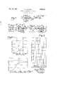
Figure 1 is an elevation View, partly in cross section and partly' diagrammatic, of a preferred embodiment of apparatus for frequency conversion constructed in accordance with the present invention,
Figure 2V is a schematic diagram of an essential circuit utilizing a mechanical filter unit of the present invention butin. which the filter unit is of a different type than that shown in Figure 1,
Figure 3 is a graph of I. F. output voltage vs. applied oscillator voltage applied to the driver plates of the apparatus of Figure l when the driver plates are composed of barium titanate ceramic prepolarized at 400 v. and with 1 v. signal voltage,
Figure 4 is a graph showing two curves of I. F. output, vs. bias voltage on the ceramic driver plates of the apparatus of Figure 1, one of the curves being for harmonic andthe other being/for fundamental operation when signal voltage is 1 and oscillator voltage is 25, and
Figure 5 is a graphv including four curves of relative overall I. F. output vs. signal voltage applied to the driver plates of the apparatus of Figure l, two of the curves being forfundamental mixing, with and without bias applied to a material havingI alsol been known, -asshown' in 2,695,357 Patented Nov. 23, 1954 the driver plates; and the other two curves being for harmonic; mixing.
Briefly described, vthe present invention comprises improved apparatus for converting electrical oscillations of a first frequency, orband of frequencies, into` electrical oscillations of another frequency or bandl of frequencies. The conversion apparatus includes a mechanical ltering unit having in driving relationship therewith a capacitor driving unit.V The capacitor unit includes at least one ceramic body having nonlinear reactance properties and electromechanical transducing properties. Voltages of two different frequencies, one of which is the frequency a harmonic of the other. Vibration of the ceramic plate is transmitted to the filtering unit causing it to vibrate in unison. The apparatus also includes means responsive to vibration of the filter unit for converting the mechanical vibrations of the filter unit into corresponding electrical oscillations.
the bar may be of aluminum and may have a length of about 4 inches. Neither the thickness nor the width of the bar is critical but, for convenience, the bar may be fabricated so that it has a width about 1A inch and a thickness of about 1/16 inch.
A driving means 4 is provided for mechanically vibrating the bar 2. This driving means may comprise a dual capacitor unit having two thin plates 6 and 8 of a barium titanate .non-linear, ceramic, high dielectric material mounted on opposite faces of the bar. These plates may have dimensions of say 1/2 inch by thickness of 2O mils but this is by no means critical. plates 6 and.8 are united to opposite with layers of solder 10 and 12 face of each plate is plated with and 16, such as silver. The edges of the plates are not metal-coated. In order to apply maximum driving force to the bar, the capacitor plates should be attached at a quarter wavelength point. Instead of the preferred'pair of plates, a single plate of larger area than either one of they plates 6 or 8 may be used.
Each of the capacitor units is leads 18, 20
The faces of the filter bar and the` exposed major a thin lm of metal 14 provided with a pair of and 22, 24, respectively, each pair being soldered to its ceramic plate in a single connection. The leads 18 and 22 are connected to a source of the frequency being converted. This may be an R. F. signal generator, as shown in Figure 2. The other lead, 20 or 24, of each pair, is connected to a source of voltage having a frequency which is to be mixed with the signal frequency. This may be an R. F. oscillator, as also shown in Figure 2.
The filter bar is also provided with means for converting the mechanical vibrations of the bar into corresponding electrical oscillations. This may comprise another capacitor unit 26 which includes a thin plate 28 of barium titanate ceramic material similar in dimension and composition to the plates 6 and 8 included in the driving means. The ceramic plate 28 is soldered to either major face of the bar, preferably at another quarter wavelength point. The exposed major face of the plate is given a thin coating 30 of a metal, such as silver, and provided with a lead 32.
The filter bar is also provided with a ground connection 34. The bar may mounted in any suitable manner, to permit free vibration. For example, it may be simply suspended by its leads or clamped at nodal peints. If the clamps are applied at the sidesv of the bar they will not interfere with the capacitor units. The meli inch in area and a.
chanical filter u nit, constructed as above described, is a particular type that can be used only in special ap plications where conversion of only a single frequency to another single frequency is desired.
A type of filter unit having much broader application is included in Figure 2. This unit comprises a ar of metal 36, having a plurality of sections 38 of a particular diameter and joined by connecting sections 40 of lesser diameter. Each of the end sections 38a and 38.5 has a ceramic driving or pick up unit 42 and 44, respectively, of similar construction, of these ceramic units comprises a thin ceramic plate 46 having a diameter the same as that of the filter bar section in which it is included, soldered between halves of the filter bar section. The filter bar section is cut trans'- versely to permit insertion of the ceramic.
Lead connections are made to either side of the ceramic Y plate in the same manner as described in connection with the filter unit of Figure 1.
This filter unit is capable of passing an entire band of frequencies and may therefore be utilized in radioV receiver applications.
Continuing to refer to Figure 2, as in a superheterodyne receiver, an R. F. signal of a particular frequency, or band of frequencies, may be picked up by an antenna 48 and amplified by an R. F. amplifier 5t). The output of the R. F. amplifier may befcoupled to the ceramic unit 42 through a transformer 52 and tuning capacitor 54. In a practical experimental example, the signal frequency was 153 kc.
A voltage of a second frequency is also applied to the ceramic driving unit from a second source such as an oscillator-56. This voltage may be coupled to the plates of the unit 42 through a transformer 58, and a capacitor 60. The second frequency depends upon the frequency, or band of frequencies, into which it is desired to convert the signal frequency. lf, for example, it is desired to convert the signal frequency into an intermediate frequency voltage signal of 50 kc., the filter bar is designed so that it will resonate within a band of frequencies including 50 kc. and the oscillator 56 maybe adjusted to have an output frequency of 203 kc.
When the two frequencies are applied to the driver unit, two distinct effects result. Since the barium titanate ceramic driver plate has electromechanical transducing properties, the varying voltage across the metallic plates of the capacitor causes the ceramic to vibrate. Due to the mixing properties of the ceramic, the frequency of vibration is the difference of the two applied frequencies. It could also be the sum of the two frequencies. It has previously been known that certain ceramics such as the barium titanate high dielectric ceramics have nonlinear properties which enable them to act as mixers.
In the past, however, when the electromechanical transducing and the mixing properties of the ceramic have been utilized it has been customary to feed the intermediate frequency of the output directly to an I. F. amplilier with the usual vacuum tube circuits. However, the
type of frequency signal obtained by this method is not as sharp and free from side band effects, and the like, as may be desired for some purposes.
In the present invention, the vibration of the ceramic driver plates sets the filter bar in vibration at a resonant frequenc Still referring to Figure 2, vibrations of the filter bar are communicated to the transducer unit 44 which is also caused to vibrate at the resonant frequency of the bar. The electromechanical properties of the ceramic plate 46 of the transducing unit 44 cause the mechanical vibrations to be converted into corresponding electrical oscillations which may be fed through an output lead 62 to any output utilization circuit such as an I. F. amplifier, 64. From the I. F. amplifier the signal may be fed to an audio detector and conventional audio amplifier and reproducing system as in a superheterodyne radio receiver.
The output of the transducing unit 44 is coupled to. the I. F. amplifier through a transformer 66 having a tuning capacitor 68 in parallel with its secondary. A bypass capacitor 70 is connected between the primary of the transformer and ground. Although not absolutely necessary, a source of D.C. bias voltage, such as a battery 71 may be connected across the solder electrodes of the ceramic plate 46 and in series with the` primary of the transformer 66. The use of a bias voltage on included therein. Each .are tuned such that the transducer unit raises the strength of the output signal obtained therefrom. In some cases, a required however. The ceramic plate 46 may be prepolarized and the residual bias remaining after the polarizing voltage is removed may be relied upon. Y Higher I. F. voltage output is obtained when the resultant mixer voltage has a frequency which is the sum or difference of the signal voltage frequency and a harmonic of the oscillator voltage frequency than when it is equal to the sum or difference of the signal voltage frequency and the fundamental of the oscillator frequency. This is illustrated in Figures 3 and 4. In Figure 3, relative I. F. output voltage is plotted against applied oscillator voltage. As shown by curve A, there is a substantially linear relationship between I. F. output and applied oscillator voltage when the fundamental oscillator frequency is utilized. There is also a linear relationship when the harmonic frequency of the oscillator is utilized but the output is generally much higher in the latter case, as shown by curve B. In one case, as an example, the operating frequency of the bar was 5G kc., ignal frequency 153 kc., and oscillator frequency 101.5 'c. the mixer was l53-[2(101.5)].
The effect on fundamental and output of utilizing a bias voltage on plates is shown in the graph of Figure 4. Means for applying a D.C. bias to the plates of the driver unit is shown in Figure 2. As shown in Fig. 2, a battery 72 and harmonic operation an inductance 73 in series are connected across metal bias voltage reaches a value equal to about 5 times the' bias voltage causes al oscillator voltage, an increase in sharp increase in I. F. output voltage. which is the curve lator, shows that the I. F. outputfor harmonic operation remains above the output for fundamental operation although the difference becomes much less when the bias voltage is increased. Harmonic operation output voltage is nearly independent of bias voltage.
It has also been found that when the bias voltage is kept constant, an increase in signal voltage produces a corresponding increase in relative I. F. voltage output. The increase is much plied to the driver plates than when no bias is applied and harmonic operation of the oscillator results in much greater increases' than fundamental operation. Referring to Figure 5, curves E operation with 0 and 160 v. and H are for bias respectively. volts.
Various substitutions can be made within the scope of Also, curve D,
bias respectively. Curves G The oscillator was operated at 10 thereof. The full wavelength bar, shown may be replaced with a band pass filter as shown in Figure 2, or may be several wavelengths long. The material of the bar can be anything which has good elasticity and rigidity and to which the driver plates can be aluminum and magnesium, steels united. Alloys of brass, etc. may be used. Y
Ceramic materials other than straight barium titanateA For example,
can also be used for the transducer plates. barium-strontium titanates can be used, also combinations of barium titanate and various stannates.
Besides the arrangement of the ceramic plates shown in f forms may be used. For l Figures l and 2, various other example, the ceramic may be a sleeve which fits snugly around the filter bar.
In practical operation, of the apparatus, the circuits they offer a high impedance to all the frequencies involved. This tuning is aided by,proper` selection of capacitor values. The objective is, of course,
to apply the highest percentage of the available signal voltage to the driver unit.
What is claimed is:
1. An apparatus for electromechanically converting bias voltage is not f Signal voltage was 1 volt. Resultant frequency of the ceramic driver for harmonic operation of the oscil-V greater when a bias voltage is apand F are for fundamental harmonic operation with 0 and 160 voltsl electrical oscillations of a first frequency into electrical oscillations of a second frequency, comprising a mechanical filter bar capable of vili-ration at said second frequency, means for driving said bar at said second fre quency, said driving means comprising a capacitor element of which the dielectric comprises a body of material having non-linear reactance and electromechanical transducing properties, said bar being positioned to vibrate in response to vibration of said body, means for applying a voltage of said rst frequency to said driving means, means for applying a voltage of another frequency to said driving means such that said body will vibrate at said second frequency and whereby said bar Will also be caused to vibrate at said second frequenc and means responsive to the mechanical vibrations of said bar for converting said mechanical vibrations into corresponding electrical oscillations.
2. Apparatus according to claim 1 in which said lter bar is a full Wavelength bar.
3. Apparatus according to claim 1 in which said dielectric is a barium titanate ceramic material.
4. Apparatus according to claim 3 including means for applying a direct current bias voltage to said capacitor element.
5. Apparatus according to claim 1 in which said lter bar is a band pass filter.
6. Apparatus according to claim 1 in which said capacitor element is positioned at a quarter Wavelength point of said bar.
References Cited in the ile of this patent UNITED STATES PATENTS Number Name Date 1,719,484 Norton July 2, 1929 1,732,710 Batsel Oct. 22, 1929 1,794,365 Chireix Mar. 3, 1931 2,387,472 Sontheimer Oct. 23, 1945 2,402,518 Wainer June 18, 1946 2,461,307 Antalek Feb. 8, 1949 2,501,488 Adler Mar. 21, 1950 2,539,268 Noble Ian. 23, 1951 2,571,019 Donley et al. Oct. 9, 1951 FOREIGN PATENTS Number Country Date 641,373 Great Britain Aug. 9, 1950
Priority Applications (1)
| Application Number | Priority Date | Filing Date | Title |
|---|---|---|---|
| US221860A US2695357A (en) | 1951-04-19 | 1951-04-19 | Frequency conversion apparatus |
Applications Claiming Priority (1)
| Application Number | Priority Date | Filing Date | Title |
|---|---|---|---|
| US221860A US2695357A (en) | 1951-04-19 | 1951-04-19 | Frequency conversion apparatus |
Publications (1)
| Publication Number | Publication Date |
|---|---|
| US2695357A true US2695357A (en) | 1954-11-23 |
Family
ID=22829703
Family Applications (1)
| Application Number | Title | Priority Date | Filing Date |
|---|---|---|---|
| US221860A Expired - Lifetime US2695357A (en) | 1951-04-19 | 1951-04-19 | Frequency conversion apparatus |
Country Status (1)
| Country | Link |
|---|---|
| US (1) | US2695357A (en) |
Cited By (29)
| Publication number | Priority date | Publication date | Assignee | Title |
|---|---|---|---|---|
| US2851877A (en) * | 1955-10-07 | 1958-09-16 | Ivan L Joy | Vibration testing device |
| US2877432A (en) * | 1957-01-08 | 1959-03-10 | Clevite Corp | Electromechanical filter elements |
| US2898477A (en) * | 1955-10-31 | 1959-08-04 | Bell Telephone Labor Inc | Piezoelectric field effect semiconductor device |
| US2906971A (en) * | 1956-02-10 | 1959-09-29 | Bell Telephone Labor Inc | Torsional vibrational wave filters and delay lines |
| US2978597A (en) * | 1956-03-14 | 1961-04-04 | Harris Transducer Corp | Circuit element transducer |
| US3012204A (en) * | 1959-04-15 | 1961-12-05 | Bell Telephone Labor Inc | Elastic wave parametric amplifier |
| US3028564A (en) * | 1960-06-14 | 1962-04-03 | Kokusai Electric Co Ltd | Mechanical filter |
| US3078427A (en) * | 1958-05-30 | 1963-02-19 | Siemens Ag | Electromechanical filter with piezoelectric drive |
| US3105966A (en) * | 1960-01-04 | 1963-10-01 | Gen Electric | Doppler radar system |
| US3131368A (en) * | 1960-09-14 | 1964-04-28 | Robert W Hart | Signal selecting apparatus |
| US3142027A (en) * | 1960-02-26 | 1964-07-21 | Siemens Ag | Electromechanical wave filter having resonant bars coupled to each other by torsion wires which also support bars |
| US3146415A (en) * | 1960-02-26 | 1964-08-25 | Siemens Ag | Electromechanical filter |
| US3184683A (en) * | 1962-01-12 | 1965-05-18 | James J Murray | Mechanically excited electronic detecting element |
| US3189851A (en) * | 1962-06-04 | 1965-06-15 | Sonus Corp | Piezoelectric filter |
| US3191913A (en) * | 1961-05-22 | 1965-06-29 | Hal C Mettler | Ultrasonic unit |
| US3206698A (en) * | 1958-05-23 | 1965-09-14 | Corning Glass Works | Electro-mechanical delay line having ferroelectric transducer bonded to solid delay medium |
| US3253166A (en) * | 1963-01-28 | 1966-05-24 | Westinghouse Electric Corp | Electromechanical frequency discriminator |
| US3264585A (en) * | 1961-06-20 | 1966-08-02 | Siemens Ag | Dual electrostrictive drivers bonded to and driving opposite sides of mechanical resonator |
| US3281725A (en) * | 1961-09-28 | 1966-10-25 | Siemens Ag | Filter for electrical waves using plural resonators having similar dominant responseand different spurious response |
| US3358249A (en) * | 1961-08-22 | 1967-12-12 | Toko Inc | Folded h-shaped resonator electromechanical filter |
| US3378794A (en) * | 1964-05-19 | 1968-04-16 | Siemens Ag | Electromechanical transducer and filter |
| US3384768A (en) * | 1967-09-29 | 1968-05-21 | Clevite Corp | Piezoelectric resonator |
| DE1269255B (en) * | 1961-06-20 | 1968-05-30 | Siemens Ag | Electrostrictive coupling arrangement for a resonator executing longitudinal vibrations |
| US3437848A (en) * | 1964-09-24 | 1969-04-08 | Telefunken Patent | Piezoelectric plate filter |
| US3437849A (en) * | 1966-11-21 | 1969-04-08 | Motorola Inc | Temperature compensation of electrical devices |
| US3509387A (en) * | 1966-04-22 | 1970-04-28 | Marconi Co Ltd | Electro-mechanical resonators |
| DE1616671B1 (en) * | 1962-04-14 | 1970-07-09 | Toko Inc | Electromechanical filter |
| US4249262A (en) * | 1976-03-01 | 1981-02-03 | Siemens Aktiengesellschaft | Tunable microwave oscillator |
| US4798990A (en) * | 1986-09-11 | 1989-01-17 | Bengt Henoch | Device for transmitting electric energy to computers and data nets |
Citations (10)
| Publication number | Priority date | Publication date | Assignee | Title |
|---|---|---|---|---|
| US1719484A (en) * | 1925-07-24 | 1929-07-02 | Western Electric Co | Carrier transmission system |
| US1732710A (en) * | 1923-09-20 | 1929-10-22 | Westinghouse Electric & Mfg Co | Wireless receiving system |
| US1794365A (en) * | 1925-08-21 | 1931-03-03 | Chireix Henri | Heterodyne receiving apparatus |
| US2387472A (en) * | 1943-08-17 | 1945-10-23 | Rca Corp | Square-law detector |
| US2402518A (en) * | 1943-06-11 | 1946-06-18 | Titanium Alloy Mfg Co | High dielectric material and method of making same |
| US2461307A (en) * | 1944-11-13 | 1949-02-08 | Rauland Corp | Modulating system |
| US2501488A (en) * | 1946-07-19 | 1950-03-21 | Zenith Radio Corp | Magnetostrictively driven mechanical wave filter |
| GB641373A (en) * | 1946-12-31 | 1950-08-09 | Rca Corp | Signal modulation network |
| US2539268A (en) * | 1945-04-25 | 1951-01-23 | Motorola Inc | Oscillator |
| US2571019A (en) * | 1948-04-30 | 1951-10-09 | Rca Corp | Electrical coupling system for magnetostrictive elements |
-
1951
- 1951-04-19 US US221860A patent/US2695357A/en not_active Expired - Lifetime
Patent Citations (10)
| Publication number | Priority date | Publication date | Assignee | Title |
|---|---|---|---|---|
| US1732710A (en) * | 1923-09-20 | 1929-10-22 | Westinghouse Electric & Mfg Co | Wireless receiving system |
| US1719484A (en) * | 1925-07-24 | 1929-07-02 | Western Electric Co | Carrier transmission system |
| US1794365A (en) * | 1925-08-21 | 1931-03-03 | Chireix Henri | Heterodyne receiving apparatus |
| US2402518A (en) * | 1943-06-11 | 1946-06-18 | Titanium Alloy Mfg Co | High dielectric material and method of making same |
| US2387472A (en) * | 1943-08-17 | 1945-10-23 | Rca Corp | Square-law detector |
| US2461307A (en) * | 1944-11-13 | 1949-02-08 | Rauland Corp | Modulating system |
| US2539268A (en) * | 1945-04-25 | 1951-01-23 | Motorola Inc | Oscillator |
| US2501488A (en) * | 1946-07-19 | 1950-03-21 | Zenith Radio Corp | Magnetostrictively driven mechanical wave filter |
| GB641373A (en) * | 1946-12-31 | 1950-08-09 | Rca Corp | Signal modulation network |
| US2571019A (en) * | 1948-04-30 | 1951-10-09 | Rca Corp | Electrical coupling system for magnetostrictive elements |
Cited By (30)
| Publication number | Priority date | Publication date | Assignee | Title |
|---|---|---|---|---|
| US2851877A (en) * | 1955-10-07 | 1958-09-16 | Ivan L Joy | Vibration testing device |
| US2898477A (en) * | 1955-10-31 | 1959-08-04 | Bell Telephone Labor Inc | Piezoelectric field effect semiconductor device |
| US2906971A (en) * | 1956-02-10 | 1959-09-29 | Bell Telephone Labor Inc | Torsional vibrational wave filters and delay lines |
| US2978597A (en) * | 1956-03-14 | 1961-04-04 | Harris Transducer Corp | Circuit element transducer |
| US2877432A (en) * | 1957-01-08 | 1959-03-10 | Clevite Corp | Electromechanical filter elements |
| US3206698A (en) * | 1958-05-23 | 1965-09-14 | Corning Glass Works | Electro-mechanical delay line having ferroelectric transducer bonded to solid delay medium |
| US3078427A (en) * | 1958-05-30 | 1963-02-19 | Siemens Ag | Electromechanical filter with piezoelectric drive |
| US3012204A (en) * | 1959-04-15 | 1961-12-05 | Bell Telephone Labor Inc | Elastic wave parametric amplifier |
| US3105966A (en) * | 1960-01-04 | 1963-10-01 | Gen Electric | Doppler radar system |
| US3146415A (en) * | 1960-02-26 | 1964-08-25 | Siemens Ag | Electromechanical filter |
| US3142027A (en) * | 1960-02-26 | 1964-07-21 | Siemens Ag | Electromechanical wave filter having resonant bars coupled to each other by torsion wires which also support bars |
| US3028564A (en) * | 1960-06-14 | 1962-04-03 | Kokusai Electric Co Ltd | Mechanical filter |
| US3131368A (en) * | 1960-09-14 | 1964-04-28 | Robert W Hart | Signal selecting apparatus |
| US3191913A (en) * | 1961-05-22 | 1965-06-29 | Hal C Mettler | Ultrasonic unit |
| US3264585A (en) * | 1961-06-20 | 1966-08-02 | Siemens Ag | Dual electrostrictive drivers bonded to and driving opposite sides of mechanical resonator |
| DE1269255B (en) * | 1961-06-20 | 1968-05-30 | Siemens Ag | Electrostrictive coupling arrangement for a resonator executing longitudinal vibrations |
| US3358249A (en) * | 1961-08-22 | 1967-12-12 | Toko Inc | Folded h-shaped resonator electromechanical filter |
| US3281725A (en) * | 1961-09-28 | 1966-10-25 | Siemens Ag | Filter for electrical waves using plural resonators having similar dominant responseand different spurious response |
| DE1616685B1 (en) * | 1961-09-28 | 1970-02-05 | Siemens Ag | Electromechanical filter |
| US3184683A (en) * | 1962-01-12 | 1965-05-18 | James J Murray | Mechanically excited electronic detecting element |
| DE1616671B1 (en) * | 1962-04-14 | 1970-07-09 | Toko Inc | Electromechanical filter |
| US3189851A (en) * | 1962-06-04 | 1965-06-15 | Sonus Corp | Piezoelectric filter |
| US3253166A (en) * | 1963-01-28 | 1966-05-24 | Westinghouse Electric Corp | Electromechanical frequency discriminator |
| US3378794A (en) * | 1964-05-19 | 1968-04-16 | Siemens Ag | Electromechanical transducer and filter |
| US3437848A (en) * | 1964-09-24 | 1969-04-08 | Telefunken Patent | Piezoelectric plate filter |
| US3509387A (en) * | 1966-04-22 | 1970-04-28 | Marconi Co Ltd | Electro-mechanical resonators |
| US3437849A (en) * | 1966-11-21 | 1969-04-08 | Motorola Inc | Temperature compensation of electrical devices |
| US3384768A (en) * | 1967-09-29 | 1968-05-21 | Clevite Corp | Piezoelectric resonator |
| US4249262A (en) * | 1976-03-01 | 1981-02-03 | Siemens Aktiengesellschaft | Tunable microwave oscillator |
| US4798990A (en) * | 1986-09-11 | 1989-01-17 | Bengt Henoch | Device for transmitting electric energy to computers and data nets |
Similar Documents
| Publication | Publication Date | Title |
|---|---|---|
| US2695357A (en) | Frequency conversion apparatus | |
| US3585537A (en) | Electric wave filters | |
| US2596460A (en) | Multichannel filter | |
| US2368643A (en) | Variable reactance and control circuit therefor | |
| US3750027A (en) | Surface wave frequency discriminators | |
| US2805400A (en) | Resonant coupling circuit | |
| US3267352A (en) | Harmonic generators utilizing a basic multiplying element resonant at both the input and output frequencies | |
| US3075097A (en) | Ultrasonic device | |
| US2753529A (en) | Electromechanical resonator | |
| US1968610A (en) | Thermionic amplifying system | |
| US3576506A (en) | Energy translating devices | |
| US3525944A (en) | Frequency discriminator circuit | |
| US2901555A (en) | Electromechanical amplifier | |
| US2985840A (en) | Gain control amplifier | |
| US3069626A (en) | Reflex amplifier circuit with volume control means | |
| US2567208A (en) | Crystal mixer for multiplex broadcasting | |
| US3217265A (en) | Electric wave filters utilizing piezoelectric resonators | |
| US2477337A (en) | Magnetic detector | |
| US2453243A (en) | Frequency modulating and harmonic producer apparatus | |
| US4006437A (en) | Frequency filter | |
| US2361664A (en) | Frequency modulation detector circuit | |
| US3648184A (en) | Fm detecting circuit having a piezoelectric filter | |
| US2908868A (en) | Electrical frequency selective circuit | |
| US3559116A (en) | Piezoelectric ceramic filter | |
| GB1105114A (en) | Electromechanical resonators and electric circuit devices utilizing the same |