US2694520A - Apparatus for separating butterfat from milk - Google Patents
Apparatus for separating butterfat from milk Download PDFInfo
- Publication number
- US2694520A US2694520A US259679A US25967951A US2694520A US 2694520 A US2694520 A US 2694520A US 259679 A US259679 A US 259679A US 25967951 A US25967951 A US 25967951A US 2694520 A US2694520 A US 2694520A
- Authority
- US
- United States
- Prior art keywords
- butterfat
- milk
- water
- separator
- separating
- Prior art date
- Legal status (The legal status is an assumption and is not a legal conclusion. Google has not performed a legal analysis and makes no representation as to the accuracy of the status listed.)
- Expired - Lifetime
Links
- 235000013336 milk Nutrition 0.000 title description 40
- 239000008267 milk Substances 0.000 title description 40
- 210000004080 milk Anatomy 0.000 title description 40
- XLYOFNOQVPJJNP-UHFFFAOYSA-N water Substances O XLYOFNOQVPJJNP-UHFFFAOYSA-N 0.000 description 33
- 239000007787 solid Substances 0.000 description 29
- 239000006071 cream Substances 0.000 description 19
- 238000000926 separation method Methods 0.000 description 11
- 235000020183 skimmed milk Nutrition 0.000 description 11
- 239000000725 suspension Substances 0.000 description 9
- 239000000203 mixture Substances 0.000 description 8
- 238000007599 discharging Methods 0.000 description 7
- 239000007900 aqueous suspension Substances 0.000 description 6
- 239000000470 constituent Substances 0.000 description 5
- 238000000034 method Methods 0.000 description 4
- 230000002093 peripheral effect Effects 0.000 description 2
- 241000135164 Timea Species 0.000 description 1
- 240000008042 Zea mays Species 0.000 description 1
- 235000005824 Zea mays ssp. parviglumis Nutrition 0.000 description 1
- 235000002017 Zea mays subsp mays Nutrition 0.000 description 1
- 235000005822 corn Nutrition 0.000 description 1
- 238000009792 diffusion process Methods 0.000 description 1
- 238000010790 dilution Methods 0.000 description 1
- 239000012895 dilution Substances 0.000 description 1
- 238000002955 isolation Methods 0.000 description 1
- 239000007788 liquid Substances 0.000 description 1
- 230000002441 reversible effect Effects 0.000 description 1
- 210000002105 tongue Anatomy 0.000 description 1
- 238000005406 washing Methods 0.000 description 1
Images


Classifications
-
- B—PERFORMING OPERATIONS; TRANSPORTING
- B04—CENTRIFUGAL APPARATUS OR MACHINES FOR CARRYING-OUT PHYSICAL OR CHEMICAL PROCESSES
- B04B—CENTRIFUGES
- B04B1/00—Centrifuges with rotary bowls provided with solid jackets for separating predominantly liquid mixtures with or without solid particles
- B04B1/04—Centrifuges with rotary bowls provided with solid jackets for separating predominantly liquid mixtures with or without solid particles with inserted separating walls
- B04B1/08—Centrifuges with rotary bowls provided with solid jackets for separating predominantly liquid mixtures with or without solid particles with inserted separating walls of conical shape
Definitions
- Cream as at present separated generally consists of Q a concentration of butterfat in milk of about 50%, with the result that, owing to the tendency to ripen, mature and finally putrify caused by the presence of the milk content it is not possible to keep the cream for any period in ordinary temperatures.
- the object of the invention is to provide a method and apparatus for the separation of butterfat in which the separated butterfat is practically free from any other constituent apart from water. With such substantially complete isolation all tendency to ripen, mature or putrify is arrested, with the result that the suspension can be kept for a substantial period of timea number of weeks-even under tropical conditions.
- the milk is subjected to separation action so that concentrated butterfat and some residual solids other than butterfat are separated from the skimmed milk, the separated butterfat and residual solids then being mixed with water, and this mixture subjected to centrifugal separation action into substantially butterfat and water on the one hand and water with residual solids on the other hand.
- the apparatus for carrying out the process according to the invention may comprise .two stage centrifugal separator means in the first stage portion of which the butterfat with some residual solids are passed into a separator chamber and separated from the skimmed milk which is discharged for collection, and the second stage portion of which corn'prises a mixing chamber in which the water and separated butterfat and other residual solids are mixed and then passed into a second separator chamber in which the butterfat substantially devoid of other solids, is once again separated out, and separate discharge means from which the butterfat in water suspension constitutent on the one hand and the water and residual solids are discharged for collection.
- the mixing chamber may be combined with the second separator; or it may be a separate tank which is adapted to receive the cream and water at one end, and at the other end deliver the diffused mixture to the second separator.
- the separ tor means may comprise two separator bowls and a mixing chamber combined to form a rigid structure adapted to rotate as a single unit.
- the separator means may consist in separate separators. each comprising a single separator bowl, which are driven by separate driving means: or they may be driven simultaneously from common driving means.
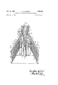
- Fig. 1 is a vertical sectional elevation on the line I-I of Fig. 2.
- Fig. 2 is a section on the line IIII of Fig. 1.
- Fig. 3 is a section on the line IlIllI of Fig. 1.
- Fig. 4 is a sectional view of the feed control to the separator.
- 1 is a conical bowl top which rests on a rubber ring 2 lying in a groove formed by the flanged edge of a bowl bottom 3, the two portions being held together by means of a central column 4 rigidly secured to the bottom 3,
- the upper end of the column 4 is constituted by a tubular portion 8 having discharge orifices on its lower end at 8a, and which is externally threaded to receive the nut 5.
- the upper portion of the column proper 4 is axially bored at 411 for about half its length, and has inserted in the bore 4a a central tube 9.
- the lower end of the bore 4a and tube 9 has a discharge port 4b leading to the upper end of a milk distributor 10 which is keyed to the column 4, and which has orifices 10a at its lower end.
- the milk is introduced to the separator through the tube 9.
- a collecting hood 12 Spaced above the plates 11 and also keyed to the distributor 10 is a collecting hood 12 which but for an annular cream outlet 12a (Fig. 2) is solid. It is provided with radial ribs on its sloping under side for spacing purposes. This hood completely isolates the above described first stage separator chamber from the second stage separator chamber now to be described.
- the collector 13 is held down by a bell-like member 14, whose inner surface with the outer surface of the cream collector 13 constitutes a mixing chamber.
- the upper end of the member 14 fits tightly around the upper end of the tube 8, and a distance piece 15 serves to maintain it pressed on the outer perimeter of the portion 13a.
- Adiustable jets 13b are screwed into the up er end of the collector 13 for discharging cream from the collector 13 into the mixing chamber: said iets 13b being of any desired form, and may comprise plugs orinserts (not shown) having orifices therethrough and which may be interchanged as desired or may comprise plugs with means for adjusting the sizes of the openings; while in the tube 8 openings are formed at 8a for the introduction of ater into the mixing chamber. Openings are also formed all around at the lower end of the mixing chamber at 14a, for discharging the mixture.
- the member 14 is splined to receive a series of conical plates 16 having holes 16a. These plates 16 are similar to the plates 11, except that their inner and outer diameters are of different sizes from those of the latter.
- a collecting hood 17 which is keyed to the tubular portion 8. This hood extends up to the nut 5 which abuts against it.
- a discharge orifice at 17a for discharging into a collector 17x of usual form the suspension of butterfat in water-which travels up the underside of the hood 17.
- the orifice 17a is adjustable so that the percentage of butterfat in the suspension may be varied.
- hood 18 with spacing radial ridges on its under-side and topside is arranged over and keyed to the hood 17, its lower end terminating in a short cylindrical skirt 18a whose lowermost edge fits into a groove formed by the turned up flange 12! on the lower edge of' the hood 12.
- the neck of the hood. 18 makes a tight fit with the neck of the hood 17.
- the hood 18 forms with the hood 17 a passage for the discharge of water mixed with the solid residual constituents of the cream, other than butterfat, into a collecting. cover 18x through the discharge orifice 18b.
- the hood 18 also forms with the casing 1 a passage for the discharge. of skimmed milk which is finally discharged through the discharge orifice 1a into a collecting cover 1x.
- the above assembly constitutes the separator bowl.
- a partitioned container Arranged above the separator bowl is a partitioned container which is divided horizontally into two compartments, the lower19for the water, and the upper 20-for the milk.
- the water flows from the container 19 through an annular passage formed between two co-axial tubes 21, 22 into the annular passage formed between the tubes 8 and 9 of the separator; while the milk flows down a central tube 23 which passes down the tube- 21 and discharges into the tube 9.
- the two compartments 19, 20 are respectively fed by float controlled cocks 24, 25.
- the separator In operation, the separator is set in motion, and the milk and water suppliesv are turned on at the cocks 24 and 25 respectively so that the desired amount of flow of milk and water is about equal.
- the milk flows down the tube 9 and enters the distributor 10 by the port 4b. From here milk spreads out over the floor of the bowl bottom 3 from the holes 10a at the lower end of the distributor 10, and rises through the holes 11b in the conical plates 11. At the same time the heavier skimmed milk tends to deviate outwards between the plates- 11 and eventually discharges from their outer edges and proceeds up between the bowl top 1 and the collecting hood 18 to the outlet 1a and thence to the collecting cover 1x.
- the butterfat being the lighter, tends to pass inwards between the plates 11, and, owing to the regulation at the cream outlets 13b, it does so accompanied by sufiicient milk to keep it fiuid.
- the cream having arrived at the inner edges of the plates 11. passes upwards along the-outside of the distributor 10 through the spaces 11a and 12a, and is eventually collected by the collector 13. From the collector 13 the cream is ejected from the cream holes 13b into the mixing chamber where it meets jets of water from the'orifices 8a. The jets from the orifices 13b and 8a, impinge together on the member 14 to enable the cream and water to mingle evenly to produce a suspension.
- The. mixed water and cream now falls to the bottom of' the mixing chamber by which time diffusion of the butterfat globules in the water is complete, and the mixture is discharged from the orifices Me at the lower end of the member 14. Thence it works under the. lower plate 16 until it arrives at the holes 16a provided for its upward passage. As it proceeds through these holes the water, carrying with it the bulk of the solid constituents of the milk originally present in the cream from the first stage, except the butterfat, deviates outwards between the plates 16, and having reached the outer edges of the plates proceeds upwards between the collectinghoods 17 and 18 to the discharge 1817 from which it is ejected into a collecting cover 18x.
- the butterfat together with sufficient water to render it liquid proceeds in between the plates 16 in an inward direction and rises through the. annular spaces formed between the inner edges of the plates 16 and the member 14, whence it rises under. the collecting hood 17 to the hole discharge orifice 17a from which. it is ejected into a collecting cover 17x.
- the roles of the upper and lower compartments are reversible, if such is preferred in the interests of design; or the double function in the bowl as described may be achieved by using either twin bowls on one separator, or two separators bracketed together, each with a single bowl.
- the first bowl carries out normal separation according to existing practice, and the second bowl 80 after receiving suitable mixed water and cream, Carries out the separation of butterfat from the bulk of the remaining solid constituents present in the cream.
- a third separation or second dilution may be achieved by adding a third compartment to the separator bowl, the water supply to each of the two washing stages being supplied through the same tube with holes at different levels.
- An improved method of centrifugally separating butterfat from milk in separate stages which comprises in the first stage in feeding the milk into a locus oi centrifugal force and separating the butterfat and the residual milk solids from the skimmed milk; discharging the skimmed milk from the locus; adding water in the second stage to the mixture of separated butterfat residual and the milk solids which accompany. the butterfat, and then separating: the mixture by centrifugal separation in said second stage into butterfat in water suspension on the one hand, and water with. the residual milk solids present after the first separation on the other hand; and finally discharging each suspension from the locus.
- Centrifugal apparatus for separating butterfat from milk comprising, in combination, at least two centrifugal separator units; means for rotating said units; means for feeding milk into the first unit; means in the first unit for separating. butterfat and residual milk solids from the skimmed milk; means in the second unit for separating a mixture of butterfat with residual milk solids and water into a suspension of butterfat in water, and into waterwith the residual milk solids present after the first separation; said first. unit having a peripheral outlet for the removal of skimmed milk; a second outlet in the first unit for'the evacuation of butterfat with residual solids into a.
- mixing chamber disposed between the first and second units; means for introducing water into the said chamber; means for conveying butterfat with residual solids from the chamber to the second separator unit, and means for discharging water suspensions of butterfat, and water suspensions of residual solids, from the second separator unit.
- centrifugal separator units are' arranged in one machine having a. single drive, the first unit separating butterfat with residual milk solids from the. skimmed milk, and the second unit separating the butterfat suspension in water'from'the. water carrying away the residual milk solids present with. the butterfat after the first separation.
- Centrifugal apparatus for separating butterfat from milk comprising; in combination, at least two centrifugal separator units; means for rotating said units; means in the first unit for separating butterfat and residual milk solids from skimmed milk; means in the second unit for separating a mixture of butterfat with residual milk solids and water into a suspension of butterfat in water, and into water with the.
- said first unit having a peripheral outlet for the removal of skimmed milk; a second outlet in the first unit for the evacuation of butterfat with residual solids into a mixing chamber disposed between the first and second units; means for conveying butterfat with residual solids from the chamber to the second separator unit, means for discharging water suspensions of butterfat, and water suspensions of residual solids, from the second separator unit; said apparatus including a two-compartment container, a float controlled cock in each container, said cocks being adapted for connection to a milk supply and water supply respectively; tube means for feeding the milk in the milk container to the first separator unit; and second tube means for feeding water in the water container to the mixing chamber.
Landscapes
- Dairy Products (AREA)
Description
Nov. 16, 1954 v. o. GOUMENT 2,694,520
APPARATUS FOR SEPARATING BUTTERFAT FROM MILK Filed D80. 5, 1951 4 Sheets-Sheet l Inventor Nov. 16, 1954 v. o. GOUMENT APPARATUS FOR SEPARATING BUTTERFAT FROM MILK 4 Sheets-Sheet 2 Filed Dec. 5, 1951 AtlorneyS,
V. O. GOUMENT Nov. 16, 1954 APPARATUS FOR SEPARATING BUTTERFAT FROM MILK 4 Sheets-Sheet 5 Filed Dec. 3, 1951 Nov. 16, 1954 v. o. GOUMENT 2,694,520
APPARATUS FOR SEPARATING BUTTERFAT FROM MILK Filed D60. 3, 1951 4 Sheets-Sheet 4 United States Patent APPARATUS FOR SEPARATING BUTTERFAT FROM MILK This invention consists in an improved method of and apparatus for separating butterfat from milk.
Cream as at present separated generally consists of Q a concentration of butterfat in milk of about 50%, with the result that, owing to the tendency to ripen, mature and finally putrify caused by the presence of the milk content it is not possible to keep the cream for any period in ordinary temperatures.
The object of the invention is to provide a method and apparatus for the separation of butterfat in which the separated butterfat is practically free from any other constituent apart from water. With such substantially complete isolation all tendency to ripen, mature or putrify is arrested, with the result that the suspension can be kept for a substantial period of timea number of weeks-even under tropical conditions.
According to the invention the milk is subjected to separation action so that concentrated butterfat and some residual solids other than butterfat are separated from the skimmed milk, the separated butterfat and residual solids then being mixed with water, and this mixture subjected to centrifugal separation action into substantially butterfat and water on the one hand and water with residual solids on the other hand.
The apparatus for carrying out the process according to the invention may comprise .two stage centrifugal separator means in the first stage portion of which the butterfat with some residual solids are passed into a separator chamber and separated from the skimmed milk which is discharged for collection, and the second stage portion of which corn'prises a mixing chamber in which the water and separated butterfat and other residual solids are mixed and then passed into a second separator chamber in which the butterfat substantially devoid of other solids, is once again separated out, and separate discharge means from which the butterfat in water suspension constitutent on the one hand and the water and residual solids are discharged for collection.
The mixing chamber may be combined with the second separator; or it may be a separate tank which is adapted to receive the cream and water at one end, and at the other end deliver the diffused mixture to the second separator. According to another form the separ tor means may comprise two separator bowls and a mixing chamber combined to form a rigid structure adapted to rotate as a single unit. According to a still further form" the separator means may consist in separate separators. each comprising a single separator bowl, which are driven by separate driving means: or they may be driven simultaneously from common driving means.
The invention will now be described by way of example with reference to the accompanying semi-diagrammatic drawings which show one form of separator bowl with the outer casing omitted in which two separators are combined in a single rigid structure.
In the said drawings:
Fig. 1 is a vertical sectional elevation on the line I-I of Fig. 2.
Fig. 2 is a section on the line IIII of Fig. 1.
Fig. 3 is a section on the line IlIllI of Fig. 1.
Fig. 4 is a sectional view of the feed control to the separator.
Referring more particularly to the drawings, 1 is a conical bowl top which rests on a rubber ring 2 lying in a groove formed by the flanged edge of a bowl bottom 3, the two portions being held together by means of a central column 4 rigidly secured to the bottom 3,
2,694,520 Patented Nov. 16, 1954 and threaded at its upper end to receive a large diameter nut 5 having an annular groove which receives the neck portion of the bowl top 1. An opening 1a is formed in the neck portion to allow of the discharge of the various constituents. This assembly forms the outer casing which holds together the rest of the parts constituting the separator bowl. The lower portion of thecolumn 4 is bored to receive the driving spindle 6 of the separator driving mechanism (not shown), the upper end of the spindle 6 being slotted for engagement with a transverse pin 7 which transmits the drive to the column 4.
The upper end of the column 4 is constituted by a tubular portion 8 having discharge orifices on its lower end at 8a, and which is externally threaded to receive the nut 5. The upper portion of the column proper 4 is axially bored at 411 for about half its length, and has inserted in the bore 4a a central tube 9. The lower end of the bore 4a and tube 9 has a discharge port 4b leading to the upper end of a milk distributor 10 which is keyed to the column 4, and which has orifices 10a at its lower end. The milk is introduced to the separator through the tube 9.
Vertical, splines or ridges 10b are formed on the distributor 10 to receive corresponding cut-out recesses in the necks-one being larger than the others0f a series of conical plates 11 of identical shape, so that they are interchangeable. The bore of the plates 11 is such that a small annular opening is left at 11a (Fig. 3) between them and the distributor 10 to enable cream to rise up along the distributor. About a third of the distance down the sloping sides of the plates 11 a series of equally spaced holes are formed at 11b. The plates 11 are spaced apart for example by means of the punched out and doubled over tongues 11c, which leave the holes 11b. in view of the identical form of the plates 11, the holes 11b coincide and thus are vertically above one another. A passage is thus provided through which milk can rise through the plates.
Spaced above the plates 11 and also keyed to the distributor 10 is a collecting hood 12 which but for an annular cream outlet 12a (Fig. 2) is solid. It is provided with radial ribs on its sloping under side for spacing purposes. This hood completely isolates the above described first stage separator chamber from the second stage separator chamber now to be described.
Keyed to the column 4 is a cream collector 13, the
lower portion of the collector being flared outwards at 13a to cover the cream outlets 12a and 11a in the in the hood 12 and plates 11. The collector 13 is held down by a bell-like member 14, whose inner surface with the outer surface of the cream collector 13 constitutes a mixing chamber. The upper end of the member 14 fits tightly around the upper end of the tube 8, and a distance piece 15 serves to maintain it pressed on the outer perimeter of the portion 13a. Adiustable jets 13b are screwed into the up er end of the collector 13 for discharging cream from the collector 13 into the mixing chamber: said iets 13b being of any desired form, and may comprise plugs orinserts (not shown) having orifices therethrough and which may be interchanged as desired or may comprise plugs with means for adjusting the sizes of the openings; while in the tube 8 openings are formed at 8a for the introduction of ater into the mixing chamber. Openings are also formed all around at the lower end of the mixing chamber at 14a, for discharging the mixture.
The member 14 is splined to receive a series of conical plates 16 having holes 16a. These plates 16 are similar to the plates 11, except that their inner and outer diameters are of different sizes from those of the latter.
Over the plates 16 there is arranged a collecting hood 17 which is keyed to the tubular portion 8. This hood extends up to the nut 5 which abuts against it. At its upper end in its neck portion there is a discharge orifice at 17a for discharging into a collector 17x of usual form the suspension of butterfat in water-which travels up the underside of the hood 17. The orifice 17a is adjustable so that the percentage of butterfat in the suspension may be varied.
,A further collecting hood 18 with spacing radial ridges on its under-side and topside is arranged over and keyed to the hood 17, its lower end terminating in a short cylindrical skirt 18a whose lowermost edge fits into a groove formed by the turned up flange 12!) on the lower edge of' the hood 12. The neck of the hood. 18 makes a tight fit with the neck of the hood 17. The hood 18 forms with the hood 17 a passage for the discharge of water mixed with the solid residual constituents of the cream, other than butterfat, into a collecting. cover 18x through the discharge orifice 18b. The hood 18 also forms with the casing 1 a passage for the discharge. of skimmed milk which is finally discharged through the discharge orifice 1a into a collecting cover 1x.
The above assembly constitutes the separator bowl.
Arranged above the separator bowl is a partitioned container which is divided horizontally into two compartments, the lower19for the water, and the upper 20-for the milk. The water flows from the container 19 through an annular passage formed between two co-axial tubes 21, 22 into the annular passage formed between the tubes 8 and 9 of the separator; while the milk flows down a central tube 23 which passes down the tube- 21 and discharges into the tube 9. The two compartments 19, 20 are respectively fed by float controlled cocks 24, 25.
In operation, the separator is set in motion, and the milk and water suppliesv are turned on at the cocks 24 and 25 respectively so that the desired amount of flow of milk and water is about equal. The milk flows down the tube 9 and enters the distributor 10 by the port 4b. From here milk spreads out over the floor of the bowl bottom 3 from the holes 10a at the lower end of the distributor 10, and rises through the holes 11b in the conical plates 11. At the same time the heavier skimmed milk tends to deviate outwards between the plates- 11 and eventually discharges from their outer edges and proceeds up between the bowl top 1 and the collecting hood 18 to the outlet 1a and thence to the collecting cover 1x.
The butterfat, being the lighter, tends to pass inwards between the plates 11, and, owing to the regulation at the cream outlets 13b, it does so accompanied by sufiicient milk to keep it fiuid. The cream having arrived at the inner edges of the plates 11. passes upwards along the-outside of the distributor 10 through the spaces 11a and 12a, and is eventually collected by the collector 13. From the collector 13 the cream is ejected from the cream holes 13b into the mixing chamber where it meets jets of water from the'orifices 8a. The jets from the orifices 13b and 8a, impinge together on the member 14 to enable the cream and water to mingle evenly to produce a suspension.
The. mixed water and cream now falls to the bottom of' the mixing chamber by which time diffusion of the butterfat globules in the water is complete, and the mixture is discharged from the orifices Me at the lower end of the member 14. Thence it works under the. lower plate 16 until it arrives at the holes 16a provided for its upward passage. As it proceeds through these holes the water, carrying with it the bulk of the solid constituents of the milk originally present in the cream from the first stage, except the butterfat, deviates outwards between the plates 16, and having reached the outer edges of the plates proceeds upwards between the collectinghoods 17 and 18 to the discharge 1817 from which it is ejected into a collecting cover 18x.
The butterfat together with sufficient water to render it liquid proceeds in between the plates 16 in an inward direction and rises through the. annular spaces formed between the inner edges of the plates 16 and the member 14, whence it rises under. the collecting hood 17 to the hole discharge orifice 17a from which. it is ejected into a collecting cover 17x.
The roles of the upper and lower compartments are reversible, if such is preferred in the interests of design; or the double function in the bowl as described may be achieved by using either twin bowls on one separator, or two separators bracketed together, each with a single bowl. The first bowl carries out normal separation according to existing practice, and the second bowl 80 after receiving suitable mixed water and cream, Carries out the separation of butterfat from the bulk of the remaining solid constituents present in the cream.
If for any reason, such as lengthy storage of the suspension, it is desirable to remove the last traces of solids other than butterfat, a third separation or second dilution may be achieved by adding a third compartment to the separator bowl, the water supply to each of the two washing stages being supplied through the same tube with holes at different levels.
I claim:
1. An improved method of centrifugally separating butterfat from milk in separate stages, which comprises in the first stage in feeding the milk into a locus oi centrifugal force and separating the butterfat and the residual milk solids from the skimmed milk; discharging the skimmed milk from the locus; adding water in the second stage to the mixture of separated butterfat residual and the milk solids which accompany. the butterfat, and then separating: the mixture by centrifugal separation in said second stage into butterfat in water suspension on the one hand, and water with. the residual milk solids present after the first separation on the other hand; and finally discharging each suspension from the locus.
2. Centrifugal apparatus for separating butterfat from milk comprising, in combination, at least two centrifugal separator units; means for rotating said units; means for feeding milk into the first unit; means in the first unit for separating. butterfat and residual milk solids from the skimmed milk; means in the second unit for separating a mixture of butterfat with residual milk solids and water into a suspension of butterfat in water, and into waterwith the residual milk solids present after the first separation; said first. unit having a peripheral outlet for the removal of skimmed milk; a second outlet in the first unit for'the evacuation of butterfat with residual solids into a. mixing chamber disposed between the first and second units; means for introducing water into the said chamber; means for conveying butterfat with residual solids from the chamber to the second separator unit, and means for discharging water suspensions of butterfat, and water suspensions of residual solids, from the second separator unit.
3. Apparatus according to claim 2 wherein the centrifugal separator units are' arranged in one machine having a. single drive, the first unit separating butterfat with residual milk solids from the. skimmed milk, and the second unit separating the butterfat suspension in water'from'the. water carrying away the residual milk solids present with. the butterfat after the first separation.
4. Centrifugal apparatus for separating butterfat from milk comprising; in combination, at least two centrifugal separator units; means for rotating said units; means in the first unit for separating butterfat and residual milk solids from skimmed milk; means in the second unit for separating a mixture of butterfat with residual milk solids and water into a suspension of butterfat in water, and into water with the. residual milk solids present after the first separation; said first unit having a peripheral outlet for the removal of skimmed milk; a second outlet in the first unit for the evacuation of butterfat with residual solids into a mixing chamber disposed between the first and second units; means for conveying butterfat with residual solids from the chamber to the second separator unit, means for discharging water suspensions of butterfat, and water suspensions of residual solids, from the second separator unit; said apparatus including a two-compartment container, a float controlled cock in each container, said cocks being adapted for connection to a milk supply and water supply respectively; tube means for feeding the milk in the milk container to the first separator unit; and second tube means for feeding water in the water container to the mixing chamber.
References Cited in the file of this patent UNITED. STATES PATENTS Number Name Date 1,269,254 Brown June 11, 1918 2,313,540: Hall Mar. 9, 1943
Priority Applications (1)
| Application Number | Priority Date | Filing Date | Title |
|---|---|---|---|
| US259679A US2694520A (en) | 1951-12-03 | 1951-12-03 | Apparatus for separating butterfat from milk |
Applications Claiming Priority (1)
| Application Number | Priority Date | Filing Date | Title |
|---|---|---|---|
| US259679A US2694520A (en) | 1951-12-03 | 1951-12-03 | Apparatus for separating butterfat from milk |
Publications (1)
| Publication Number | Publication Date |
|---|---|
| US2694520A true US2694520A (en) | 1954-11-16 |
Family
ID=22985924
Family Applications (1)
| Application Number | Title | Priority Date | Filing Date |
|---|---|---|---|
| US259679A Expired - Lifetime US2694520A (en) | 1951-12-03 | 1951-12-03 | Apparatus for separating butterfat from milk |
Country Status (1)
| Country | Link |
|---|---|
| US (1) | US2694520A (en) |
Cited By (2)
| Publication number | Priority date | Publication date | Assignee | Title |
|---|---|---|---|---|
| FR2640523A1 (en) * | 1988-12-21 | 1990-06-22 | Westfalia Separator Ag | PROCESS FOR THE CENTRIFUGAL TREATMENT OF CHEESE MILK AND CENTRIFUGE FOR CARRYING OUT SAID METHOD |
| US5509882A (en) * | 1994-09-12 | 1996-04-23 | Tetra Laval Holdings & Finance S.A. | Decanter centrifuge having an offset conveyor flight to aid rinsing |
Citations (2)
| Publication number | Priority date | Publication date | Assignee | Title |
|---|---|---|---|---|
| US1269254A (en) * | 1918-03-02 | 1918-06-11 | Samuel Brown | Liquid-supply-regulating device for cream-separators. |
| US2313540A (en) * | 1941-05-26 | 1943-03-09 | Laval Separator Co De | Machine for purifying liquids |
-
1951
- 1951-12-03 US US259679A patent/US2694520A/en not_active Expired - Lifetime
Patent Citations (2)
| Publication number | Priority date | Publication date | Assignee | Title |
|---|---|---|---|---|
| US1269254A (en) * | 1918-03-02 | 1918-06-11 | Samuel Brown | Liquid-supply-regulating device for cream-separators. |
| US2313540A (en) * | 1941-05-26 | 1943-03-09 | Laval Separator Co De | Machine for purifying liquids |
Cited By (2)
| Publication number | Priority date | Publication date | Assignee | Title |
|---|---|---|---|---|
| FR2640523A1 (en) * | 1988-12-21 | 1990-06-22 | Westfalia Separator Ag | PROCESS FOR THE CENTRIFUGAL TREATMENT OF CHEESE MILK AND CENTRIFUGE FOR CARRYING OUT SAID METHOD |
| US5509882A (en) * | 1994-09-12 | 1996-04-23 | Tetra Laval Holdings & Finance S.A. | Decanter centrifuge having an offset conveyor flight to aid rinsing |
Similar Documents
| Publication | Publication Date | Title |
|---|---|---|
| US2599619A (en) | Method and apparatus for centrifugal separation | |
| US2628021A (en) | Centrifuge with auxiliary feed arrangement | |
| US3301476A (en) | Apparatus for signaling a predetermined level in the sludge chamber of a centrifugaldrum | |
| US1473421A (en) | Centrifugal separator | |
| US3238063A (en) | Continuous centrifugal apparatus and method of continuously separating granular crystals therewith | |
| US2344888A (en) | Centrifugal separator | |
| JPS6045921B2 (en) | Continuously working full-wall countercurrent centrifugal extractor | |
| US2313540A (en) | Machine for purifying liquids | |
| US2779536A (en) | Anti-foaming centrifugal methods and apparatus | |
| US2557629A (en) | Method and apparatus for continuous centrifugal separation | |
| US2694520A (en) | Apparatus for separating butterfat from milk | |
| GB897255A (en) | Improvements in or relating to apparatus for separating liquids of different specific gravity, particularly a mixture of oil and water | |
| US3140257A (en) | Centrifugal separation process and apparatus | |
| US2394015A (en) | Centrifugal separation | |
| US2985361A (en) | Centrifuge | |
| US1749291A (en) | Centrifugal separator | |
| US2485209A (en) | Centrifuge with primary and secondary zones of separation and process therefor | |
| GB1039031A (en) | Separation process and apparatus | |
| US2612356A (en) | Homogenizing device | |
| GB260071A (en) | Improvements in and relating to centrifugal separators | |
| US1401196A (en) | Centrifugal machine | |
| US2294468A (en) | Centrifugal separator | |
| US2554495A (en) | Apparatus for separating solids according to their specific gravities | |
| US1681490A (en) | Method of making sirups | |
| US3332615A (en) | Method and apparatus for producing butter oil |