US2687769A - Venetian blind - Google Patents
Venetian blind Download PDFInfo
- Publication number
- US2687769A US2687769A US287011A US28701152A US2687769A US 2687769 A US2687769 A US 2687769A US 287011 A US287011 A US 287011A US 28701152 A US28701152 A US 28701152A US 2687769 A US2687769 A US 2687769A
- Authority
- US
- United States
- Prior art keywords
- cord
- blind
- reel
- hauling
- head
- Prior art date
- Legal status (The legal status is an assumption and is not a legal conclusion. Google has not performed a legal analysis and makes no representation as to the accuracy of the status listed.)
- Expired - Lifetime
Links
Images


Classifications
-
- E—FIXED CONSTRUCTIONS
- E06—DOORS, WINDOWS, SHUTTERS, OR ROLLER BLINDS IN GENERAL; LADDERS
- E06B—FIXED OR MOVABLE CLOSURES FOR OPENINGS IN BUILDINGS, VEHICLES, FENCES OR LIKE ENCLOSURES IN GENERAL, e.g. DOORS, WINDOWS, BLINDS, GATES
- E06B9/00—Screening or protective devices for wall or similar openings, with or without operating or securing mechanisms; Closures of similar construction
- E06B9/24—Screens or other constructions affording protection against light, especially against sunshine; Similar screens for privacy or appearance; Slat blinds
- E06B9/26—Lamellar or like blinds, e.g. venetian blinds
- E06B9/28—Lamellar or like blinds, e.g. venetian blinds with horizontal lamellae, e.g. non-liftable
- E06B9/30—Lamellar or like blinds, e.g. venetian blinds with horizontal lamellae, e.g. non-liftable liftable
- E06B9/303—Lamellar or like blinds, e.g. venetian blinds with horizontal lamellae, e.g. non-liftable liftable with ladder-tape
Definitions
- VENETIAN BLIND 7 Filed May 9, 1952 3 Sheets-Sheet 1 INVEN T OR.
- A. GERSHUNY VENE'I'IAN BLIND 3 Sheets-Sheet 2 Filed May 9, 1952' INVENTOR.
- MAURICE A GERSiHUNY ATTORNEYS Patented Aug. 31 1954 NT OFFICE VENETIAN BLIND Maurice A. Gershuny, Rye, N. Y., assignor of onehalf to Seymour P. Gershuny, Mount Vernon, N. Y.
- This invention relates, to pulley shades including Venetian and roll-up blinds employing at least two cords for raising and lowering the shade and relates more particularly to certain new and useful improvements in lifting and lowering cord systems for such shades.
- the conventional form of Venetian or roll-up blind is provided with a manually operated lifting and lowering cord system of which a section constitutes a hauling part extending downwardly from the head of the blind at its right hand side.
- the hauling part is ordinarily in the form of a free-hanging loop whose length, as measured from the head of the blind, varie from a miniinum in the. lowered position of the blind to a maximum in the raised position.
- a portion may be below the window or on the floor beneath the blind and, in its loop form in particular, presents a definite safety hazard in that individuals, particularly children, are likely to become entangled in it and suifer injury. It is a matter of record that children have been caught in such hauling parts and strangled.
- the lifting and lowering cord system of the pulley shade embodies a hauling part of fixed length and a reeling device coacting with the hauling part, the reeling device being disposed in fixed relation to the head of the blind and the construction and arrangement of the parts of the system being such that a length of cord may be payed into the hauling part at its upper or head end, and an equal length of cord payed out of the hauling part at its lower end and wound onto the reelingdevice.
- the blind may be characterized by the provision of a movable head bar, or a closed head construction employing a U,-shaped head member.
- the present invention is not intended to be restricted to the aforesaid particular forms of head construction, but is applicable to other forms as well.
- Figure 1 is a broken perspective view of a Venetian blind in lowered position embodying a typical and illustrative form of lifting and lowering cord system in accordance with this invention, wherein the reeling device is disposed at the hauling part end of the head bar;
- Figure 2 is a fragmentary view in plan of the embodiment of Figure 1, the view showing details of the cord systemand its reeling device;
- FIG. 3 is a fragmentary view in perspective of a Venetian blind in lowered position embodying a modified form of cord system in accordance with this invention wherein the reeling device is disposed centrally of the head bar;
- Figure 4 is a fragmentary view in plan of the of the cord system and its reeling device
- FIG. 5 is a fragmentary perspective view of in lowered position embodying another form of raising and lowering cord system in accordance with this invention wherein separate cord units are employed for the hauling part and the lifting and lowering part respectively;
- Figure 6 is a fragmentary view in plan of the embodiment of Figure 5, showing details of the construction and arrangement of the cord units and reeling device;
- Figure 7 is a fragmentary view in plan corresponding generally to that of Figure 6 but through one-ofapair of cord openings "chored at its-opposite'end to the showing a modified arrangement of the reelin section of the cord system;
- Figure 8 is a fragmentary view in plan corresponding generally to that of Figure 6 but distinguished therefrom in the provision of a two section reeling device;
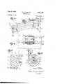
- FIG. 9 is a view in elevation of a Venetian blind installation embodying still another modification of a lifting and lowering cord system in accordance with this invention, wherein the reeling device is secured to the molding of the window in which the blind is installed;
- FIG. 9 is a somewhat enlarged view in vertical section of the reeling device of Figure 9 showing details of the reeling and cord locking mechanism.
- a Venetian blind comprising the usual head bar I, tilting bar 2 and associated cord-pulley tilting mechanismt, slats 4, bottom or elevating bar 5 and ladder tapes 6.
- a reeling device comprising a cylindrical reel 1 of suitable dimensions 'journalled for rotation on its cylinder axis by 'means of a shaft 8 supportedzat its ends in a'suitable fitting 9, is mounted as shown on the head bar l to which the fitting-9 is fixedly fastened in any convenient fashion as by bolts, screws or other suitable fastening'means (not shown).
- the reel 1 is provided with axially outstanding circular guide members It servingto partition the reel surface into a number of independent reeling sections.
- a lifting and'lowering cord element [4 secured at one end'to the elevating bar 5 leads upwardly therefrom through a set of the usual aligned cord openings 15 in the slats 4 and tilting bar 2 and IS in the head bar I to the central reeling section l2 of the winding reel.
- the cord-element I4 is anreel '1 by a suitable cord fastener 11.
- the lie and'attachment of the cord element 14 is preferably such that in the lowered position of the'blind as in Figure 1, thereel-endof 'the'cord will-pass between the reel and itsfitting 8 and thence to the top of the reel as seen in Figure'Z. This arrangement ensures I that as the reell is rotated counter-clockwise as viewed in Figure 1, the cord [4 will'lie closely along the surface of the head-bar l.
- a separate lifting and lowering cord element i8 secured at oneendito the elevating bar5 in the usual manner also leads upwardly therefrom through another set of the cord openings [5 in theslats and tilting bar and through the other of the pair 'of openings 18in the head bar -I to the endsection 13 of 'the'winding reel.
- the cord element I8 is Wrapped or snubbed around the reel '1 in at least one-and preferably two turns I'Ba as shown.
- the cord'element approaches and departs from the reeling section 13 in the same directi'on and advantageously lies between the reel and head bar, as shown in Figure 2. Thus it lies close to the head bar so as to avoid undueangularity of the cord element to the head bar.
- the cord-element l8 forms a hauling part lab and is led'downwardly through an opening 20 in the head bar and ithrough 'a cord lock 21 carried by the head bar beneath the opening.
- may be :of the usual construction well 'known in the art and cord fastener'23.
- the fastener 23 is disposed on the same side of the reel 1' as the fastener ll.
- the pull on'the hauling part lab causes a length of the cord element l8 to be payed out of the turns I811. into the upper or head bar endof the hauling part [8b.
- An equal length of the cord element I8 is caused to be payed out of the hauling part at its bottom end into the take-up part 18d and wound onto the take-up section H of the reel'T.
- the hauling part 18b is always maintained at a constant initial fixed length which is selected to ensure that the loop portion willalways'beat a safe distance above the floor in the installedposition of theblind.
- the blind may be locked in known manner at any desired elevation. It is also apparent that lowering of the blind is accomplished by gravity action in precisely the reverse manner of operation of the parts.
- thecord element I8 is reeved throughthe .left hand-opening lsas viewedin Figure 3 and .the-cordelement M is reeved through the right hand opening.
- This reversal of the cord elements necessarily requires that thecord element 14 be reeveddi- -rectly-to the-cord hook I] rather than 'be given a half wrap around the reel '1 as in Figure '2. Reeling of the-cord element on thereel-com- -mences immediately upon counterclockwise sections 25 and "26, respectively.
- the reel is-provided with a hook 21 in the section 2 5 from wmcna-nfting and lowering ordumit'lfl extelltls separate flights "Ma-and 281)throligh the reright hand end of the Figure 5.
- the opening aligned with a cord lock. bar and the hauling part 2912 passes downwardly through both for a determined distance and terminates in a U-shaped loop portion 290 serving to direct the cord element upwardly again through the opening 3
- the cord element is fastened at its other endto the top of the reel within the reeling section 26 by a suitable fastener 33.
- the pull cord 29 is continuous instead of double ended as in the embodiment of Figure '6.'
- This ar-, rangement offers the advantage that no more than one or two wraps of the pull cord need be employed in order to drive the reel 1 frictionally.
- the driving section 26 can be shorter axially since it is required to accommodate fewer turns as is apparent from a comparison of Figures 6 and '7.
- the mode of operation is otherwise analogous in all material respects to the operation of the embodiment depicted in Figure 6.
- the reel sections may be less, which is of particular advantage in connection with apparent that as downwardly, the driving section lb will be rotated counterclockwise causing the gear btomdrive the reeling section To, clockwith the embodiment shown in Figures 9 and 10,
- the reeling device is removably secured in convenient fashion to the molding at a determined distance below the top of the window as by screws 43 which pass through a removable cover cord lock member 41 is pivotally mounted on a pivot shaft 48 for pivotal movement in a relatively limited arc from the full line cord locking position to the dotted line cord released position shown in Figure 10.
- the cord lock member Figure 8 depicts a form of the reeling device wherein the reeling sections. are in the form of separate gear coupled units. In the embodiment shown, reel sections 1a and 1b, respectively, are mounted in side-by-side relation on thehead board I by means of fittings 8a and 8?), respectively.
- the reel shafts 9a and 9b of the respective sections are parallel to each other to effect proper meshing of a pair of spur gears 35a and 35b attached to the reels 1a and 1b, respectively.
- the arrangement of the cord 29 is the same as in the embodiment of Figure 6 whereas the hook 21 and hence cord 28 are reversed for obvious reasons.
- the greater axial length of the reel section lb relative to'the length of the corresponding section 26. in Figure 6 enables a greater number of turns of cord to be wound on this section.
- the reel member 49 of cylindrical contour is journalled on a shaft 50 forrotation concentrically of the casing member 45.
- a portion of the reel member 49 is displaced circumferentially inwardly to provide a hook 5
- the spring 52 concentric with the shaft 56, riveted or otherwise, is attached at its other end to the wardly circumferentially displaced to form a cord to which the loop portion 420 of the cord hauling part is secured.
- the blind is placed in its lowered position, the reel member is rotated counterclockwise to tension the spring, and the loop portion 420 then attached to. the cord hook 53 as in Figure 10 so that the hauling part 42 is under tension.
- the cord lock member. 41'- may, be: dispensed with and locking of the:cord effected. by means of. the usual cord. lock device with; whichthe head board of the blind is normally: equipped.
- the covenmemberlt may; besuitably centrally apertured' to'permit-of thapassage of the shaft 5! whose outer end maybe threaded: to receive a securing nut 54 by which: the cover member may be held: in placeon the casing- 4'5. It will be apparent, moreover, that for reasons of appearance or otherwise, itmay be advantageous to locate the reeling device elsewhere than on the window molding as in Figure 9.
- the reeling device may be fixedly disposed at the top of the window where, for example, it may .beconcealed behind the valence, boardof the blind, and the hauling partactuated, for example; by a suitable ratchet means and bead chain pull cor-darrangement, or the hauling part may berun around a pulley mounted onthe-molding andithence to the reeling device in. the head;
- cords 42a and 42b may be coupled in the head prior to entering the cord. lock 46.
- Such an. arrangement provides a single fiightof cord extending through the cord look when the blind. is in the lowered position.
Landscapes
- Engineering & Computer Science (AREA)
- Structural Engineering (AREA)
- Architecture (AREA)
- Civil Engineering (AREA)
- Blinds (AREA)
Description
g- 31, 1954 M. A. GERSHUNY 2,687,769
VENETIAN BLIND 7 Filed May 9, 1952 3 Sheets-Sheet 1 INVEN T OR. MAURICE A. GERSHUNY ,1 a wam m ATTORNEYS Aug. 31, 1954 M. A. GERSHUNY VENE'I'IAN BLIND 3 Sheets-Sheet 2 Filed May 9, 1952' INVENTOR. MAURICE A. GERSHUNY BY Mm/aw :M.
ATTORNEYS 1954 M. A; GERSHUNY 2,687,769
VENETIAN BLIND Filed May 9, 1952 3 Sheets$heet 3 32 INVEN TOR.
MAURICE A. GERSiHUNY ATTORNEYS Patented Aug. 31 1954 NT OFFICE VENETIAN BLIND Maurice A. Gershuny, Rye, N. Y., assignor of onehalf to Seymour P. Gershuny, Mount Vernon, N. Y.
Application May 9, 1952, Serial No: 287,011
1 Claim.
, This invention relates, to pulley shades including Venetian and roll-up blinds employing at least two cords for raising and lowering the shade and relates more particularly to certain new and useful improvements in lifting and lowering cord systems for such shades.
. Objects and advantages of th invention will be set forth in part hereinafter and in part will be. obvious herefrom, or may be learned by practice with the invention, the same being realized and attained by means of the combinations and improvements pointed out in the appended claim. The invention consists in th novel parts, constructions, combinations and improvements here in shown and described. j
The accompanying drawings, referred to herein and constituting a part hereof, illustrate s of the invention and, to-
various embodimen gether with the description, serve to explain the principles of the invention. The conventional form of Venetian or roll-up blind is provided with a manually operated lifting and lowering cord system of which a section constitutes a hauling part extending downwardly from the head of the blind at its right hand side.
The hauling part is ordinarily in the form of a free-hanging loop whose length, as measured from the head of the blind, varie from a miniinum in the. lowered position of the blind to a maximum in the raised position. In the maximumlength condition of the hauling part, a portion may be below the window or on the floor beneath the blind and, in its loop form in particular, presents a definite safety hazard in that individuals, particularly children, are likely to become entangled in it and suifer injury. It is a matter of record that children have been caught in such hauling parts and strangled. Variouseiforts to solve this problem, including the provision of individual tassels for the hauling embodiment of Figure 3, the view showing details part, have been made but have not been suc *-It is, therefore, an object of this invention to minimize the hazards and disadvantages attendant upon the presence in Venetian and roll-up blinds of such a variable length hauling part, through the provision of a new and improved form of. lifting and lowering cord system for use in such blinds which will automatically maintain a fixed safelength of hauling part below the head of the blind, i capable of being installed simply and efficiently at; a low cost per blind and will improve the appearance of the blind, more convenient, and. will enable. a reduction in, the length of cord required and also of the size of the cord. The reduction in length and size of the cord subject to abrasion of the cord lock thus permits of improvement in the most vulnerable part of the blind; namely, the cord, at a, minimum cost per blind.
In accordance with this invention, the lifting and lowering cord system of the pulley shade embodies a hauling part of fixed length and a reeling device coacting with the hauling part, the reeling device being disposed in fixed relation to the head of the blind and the construction and arrangement of the parts of the system being such that a length of cord may be payed into the hauling part at its upper or head end, and an equal length of cord payed out of the hauling part at its lower end and wound onto the reelingdevice. .It will be understood that in the case of Venetian blinds the blind may be characterized by the provision of a movable head bar, or a closed head construction employing a U,-shaped head member. However, it will be understood that the present invention is not intended to be restricted to the aforesaid particular forms of head construction, but is applicable to other forms as well.
Of the drawings:
Figure 1 is a broken perspective view of a Venetian blind in lowered position embodying a typical and illustrative form of lifting and lowering cord system in accordance with this invention, wherein the reeling device is disposed at the hauling part end of the head bar;
Figure 2 is a fragmentary view in plan of the embodiment ofFigure 1, the view showing details of the cord systemand its reeling device;
Figure 3 is a fragmentary view in perspective of a Venetian blind in lowered position embodying a modified form of cord system in accordance with this invention wherein the reeling device is disposed centrally of the head bar;
Figure 4 is a fragmentary view in plan of the of the cord system and its reeling device;
Figure 5 is a fragmentary perspective view of in lowered position embodying another form of raising and lowering cord system in accordance with this invention wherein separate cord units are employed for the hauling part and the lifting and lowering part respectively;
Figure 6 is a fragmentary view in plan of the embodiment of Figure 5, showing details of the construction and arrangement of the cord units and reeling device;
Figure 7 is a fragmentary view in plan corresponding generally to that of Figure 6 but through one-ofapair of cord openings "chored at its-opposite'end to the showing a modified arrangement of the reelin section of the cord system;
Figure 8 is a fragmentary view in plan corresponding generally to that of Figure 6 but distinguished therefrom in the provision of a two section reeling device;
Figure 9 is a view in elevation of a Venetian blind installation embodying still another modification of a lifting and lowering cord system in accordance with this invention, wherein the reeling device is secured to the molding of the window in which the blind is installed; and,
Figure is a somewhat enlarged view in vertical section of the reeling device of Figure 9 showing details of the reeling and cord locking mechanism.
Referring now more particularly to Figures 1 and 2 of the drawings, there is depicted a Venetian blind comprising the usual head bar I, tilting bar 2 and associated cord-pulley tilting mechanismt, slats 4, bottom or elevating bar 5 and ladder tapes 6.
"A reeling device comprising a cylindrical reel 1 of suitable dimensions 'journalled for rotation on its cylinder axis by 'means of a shaft 8 supportedzat its ends in a'suitable fitting 9, is mounted as shown on the head bar l to which the fitting-9 is fixedly fastened in any convenient fashion as by bolts, screws or other suitable fastening'means (not shown).
Advantageously, the reel 1 is provided with axially outstanding circular guide members It servingto partition the reel surface into a number of independent reeling sections. Three such reeling sections I l, 12 and I3, respectively, are depicted in Figures 1 and 2.
A lifting and'lowering cord element [4 secured at one end'to the elevating bar 5 leads upwardly therefrom through a set of the usual aligned cord openings 15 in the slats 4 and tilting bar 2 and IS in the head bar I to the central reeling section l2 of the winding reel. The cord-element I4 is anreel '1 by a suitable cord fastener 11. The lie and'attachment of the cord element 14 is preferably such that in the lowered position of the'blind as in Figure 1, thereel-endof 'the'cord will-pass between the reel and itsfitting 8 and thence to the top of the reel as seen inFigure'Z. This arrangement ensures I that as the reell is rotated counter-clockwise as viewed inFigure 1, the cord [4 will'lie closely along the surface of the head-bar l. p
A separate lifting and lowering cord element i8 secured at oneendito the elevating bar5 in the usual manner also leads upwardly therefrom through another set of the cord openings [5 in theslats and tilting bar and through the other of the pair 'of openings 18in the head bar -I to the endsection 13 of 'the'winding reel. The cord element I8 is Wrapped or snubbed around the reel '1 in at least one-and preferably two turns I'Ba as shown. The cord'element approaches and departs from the reeling section 13 in the same directi'on and advantageously lies between the reel and head bar, as shown in Figure 2. Thus it lies close to the head bar so as to avoid undueangularity of the cord element to the head bar.
Beyondthe reel 1 the cord-element l8 forms a hauling part lab and is led'downwardly through an opening 20 in the head bar and ithrough 'a cord lock 21 carried by the head bar beneath the opening. Thel'cord lock 2| may be :of the usual construction well 'known in the art and cord fastener'23. The fastener 23 is disposed on the same side of the reel 1' as the fastener ll.
It will be apparent that with the parts in the position shown in Figures 1 and 2 upon exerting a sufiicient downward pull on the hauling part 1817 to effect a downward movement thereof, the cord lock 2| will be released and the tension imparted to the cord element 18 will tighten the turns [8a and, by friction, effect a counterclock- -wise rotation of 'thereel"! as viewedi'n'Figure 1.
As the reel "1 rotates, equal lengths of the cord elements M and 18 are thuscaused to he wound onto the reeling sections 12 and I3, respectively, to raise the bottom bar 5 and thus the blind. The pull on'the hauling part lab causes a length of the cord element l8 to be payed out of the turns I811. into the upper or head bar endof the hauling part [8b. An equal length of the cord element I8 is caused to be payed out of the hauling part at its bottom end into the take-up part 18d and wound onto the take-up section H of the reel'T. Thus, the hauling part 18b is always maintained at a constant initial fixed length which is selected to ensure that the loop portion willalways'beat a safe distance above the floor in the installedposition of theblind. Manifestly, by manipulation of the hauling part 1812 relative to the cord lock2l, the blind may be locked in known manner at any desired elevation. It is also apparent that lowering of the blind is accomplished by gravity action in precisely the reverse manner of operation of the parts.
Referring now to the embodiment shown in Figures3 and 4 of the drawings, there is depicted a modified arrangement of raisingand lowering 'cord system wherein the reel 1 is mounted centrally at the head of the blind. Such an arrangement is of advantage with'parti'cu'lartypes of headmembers used in the art such, for example, as closed U-shaped heads. In accordance with the illustrative embodiment, the reeving of the lifting and lowering cords l4 and i8 'is merely reversed to the extent necessary to take account of the fact that the reel .1 is mounted between .the. cord openings l6 rather than between one of saidopenings and the end of the head -bar.as in Figure 1. 'Thus, thecord element I8 is reeved throughthe .left hand-opening lsas viewedinFigure 3 and .the-cordelement M is reeved through the right hand opening. This reversal of the cord elements necessarily requires that thecord element 14 be reeveddi- -rectly-to the-cord hook I] rather than 'be given a half wrap around the reel '1 as in Figure '2. Reeling of the-cord element on thereel-com- -mences immediately upon counterclockwise sections 25 and "26, respectively. The reel is-provided with a hook 21 in the section 2 5 from wmcna-nfting and lowering ordumit'lfl extelltls separate flights "Ma-and 281)throligh the reright hand end of the Figure 5. The opening aligned with a cord lock. bar and the hauling part 2912 passes downwardly through both for a determined distance and terminates in a U-shaped loop portion 290 serving to direct the cord element upwardly again through the opening 3| back to the reeling section 26 thus providing a take-up part 29d. The cord element is fastened at its other endto the top of the reel within the reeling section 26 by a suitable fastener 33.
It will be apparent from the foregoing that a downward pullon the hauling part 29b will effect a counterclockwise rotation of the reel 1, thus winding the cord flights 28a and 28b on the winding section to raise the blind. As in the embodiment of Figure 1, the pull on the hauling part causes a length of the cord element 29 to be payed out of the turns 29a into the upper or head bar end of the hauling part 29b. At the same time, an equal length of the cord element is payed out of the hauling part at its bottom endintothe take-up part 29d and wound onto the driving section 26. Thus, the hauling part 29?) is always maintained at a constant initial fixed safe length.
In the modification shown in Figure 7, the pull cord 29 is continuous instead of double ended as in the embodiment of Figure '6.' This ar-, rangement offers the advantage that no more than one or two wraps of the pull cord need be employed in order to drive the reel 1 frictionally. The driving section 26 can be shorter axially since it is required to accommodate fewer turns as is apparent from a comparison of Figures 6 and '7. The mode of operation is otherwise analogous in all material respects to the operation of the embodiment depicted in Figure 6.
diametercof the reel sections may be less, which is of particular advantage in connection with apparent that as downwardly, the driving section lb will be rotated counterclockwise causing the gear btomdrive the reeling section To, clockwith the embodiment shown in Figures 9 and 10,
the molding 4| of a window in which the blind is flights 42a and 42b which terminate at thelower end in the usual connecting loop portion 420. I
The reeling device is removably secured in convenient fashion to the molding at a determined distance below the top of the window as by screws 43 which pass through a removable cover cord lock member 41 is pivotally mounted on a pivot shaft 48 for pivotal movement in a relatively limited arc from the full line cord locking position to the dotted line cord released position shown in Figure 10. The cord lock member Figure 8 depicts a form of the reeling device wherein the reeling sections. are in the form of separate gear coupled units. In the embodiment shown, reel sections 1a and 1b, respectively, are mounted in side-by-side relation on thehead board I by means of fittings 8a and 8?), respectively. The reel shafts 9a and 9b of the respective sections are parallel to each other to effect proper meshing of a pair of spur gears 35a and 35b attached to the reels 1a and 1b, respectively. The arrangement of the cord 29 is the same as in the embodiment of Figure 6 whereas the hook 21 and hence cord 28 are reversed for obvious reasons. However, it will be apparent that the greater axial length of the reel section lb relative to'the length of the corresponding section 26. in Figure 6 enables a greater number of turns of cord to be wound on this section. Hence, the
hook 53 lie in the dotted line position with its locking end 4'laout of engagement with the cord sections 42a and/or 42b which lead through the cord lock section 46 to a reel member 49. I I
The reel member 49 of cylindrical contour is journalled on a shaft 50 forrotation concentrically of the casing member 45. A portion of the reel member 49 is displaced circumferentially inwardly to provide a hook 5| to which the outer end of a spiral spring 52 is attached. The spring 52, concentric with the shaft 56, riveted or otherwise, is attached at its other end to the wardly circumferentially displaced to form a cord to which the loop portion 420 of the cord hauling part is secured. In attaching the loop portion to the cord hook 53, the blind is placed in its lowered position, the reel member is rotated counterclockwise to tension the spring, and the loop portion 420 then attached to. the cord hook 53 as in Figure 10 so that the hauling part 42 is under tension. Hence, a downward pull on the hauling part to raise the blind will cause a length of cord to be payed out of the hauling part at the bottom and automatically wound onto the reel member 49 by the take-up action of the spring 52. The the cord is stored on the reel in the raised position of the blind is shown in Figure 10 and it will be understood that the circumferential disposition of the cord on the reel member 49 with respect to the hook 53 may be akin to that shown for the cord 28 and hook 21 in the arrangement of Figure 6.
It will be apparent also from Figure 10 that as the hauling part is pulled downwardly, the bottom end 41a of the cord lock member 41 will drop away from the hauling part flights 42a and a reeling device 40 is affixedto I aesme 4211.v The bottom end: of. the cord? lock' member may be provided with: a. toothed: or sharpened terminal edge: to; facilitate. gripping: of the cord flights by the. locking member. As. soon. as' man.- ual pull on theahaulingipart' is discontinued, the cord: flights 42a. andor 42b: will; tend. to move to theright as v-ievszed i'n Figure. 10; and bear against the. upper end; of. the cord lock: member 4'12 to move it from; the. released: position shown in dottedlines in Figurerl'ontoi the full line or locked position wherein the: greater the upward pull on the hauling part, dueto the. weight of the blind, the greater the; locking action. If desired, the cord lock member. 41'- may, be: dispensed with and locking of the:cord effected. by means of. the usual cord. lock device with; whichthe head board of the blind is normally: equipped.
The covenmemberltmay; besuitably centrally apertured' to'permit-of thapassage of the shaft 5! whose outer end maybe threaded: to receive a securing nut 54 by which: the cover member may be held: in placeon the casing- 4'5. It will be apparent, moreover, that for reasons of appearance or otherwise, itmay be advantageous to locate the reeling device elsewhere than on the window molding as in Figure 9. If desired, the reeling device; withasuitable modifications, may be fixedly disposed at the top of the window where, for example, it may .beconcealed behind the valence, boardof the blind, and the hauling partactuated, for example; by a suitable ratchet means and bead chain pull cor-darrangement, or the hauling part may berun around a pulley mounted onthe-molding andithence to the reeling device in. the head;
V-ar-iousother means. of connecting theireeling device into the cord system will be apparent to those skilled in the art. Thus, the cords 42a and 42b may be coupled in the head prior to entering the cord. lock 46. Such an. arrangement providesa single fiightof cord extending through the cord look when the blind. is in the lowered position.
It will be understood that various: combinations ofthe" features shown in the several modifications are within the scope-of this invention which is applicable not only to Venetian blinds but also tovarious pulley. shadesnot having slats placed in. ladder tapes, so longv as two cords are employed to. raise and lower the shade through a cord lock.
IJhe invention: in its broader aspects is not limited tovthe specific mechanisms described, but departures may be made therefrom within the scope? of: the accompanying claim withoutdeparting from; the pninciplesof the invention and without sacrificing its chief advantages.
What I claim is:
In-a Venetian blind, aliiting. and lowering cord system therefor: including: a. cord reeling device attached to the head bar of said blind; alifting and lowering cord having; a loop; portion. intermediate its ends snubbed: on said. reeling device, said cord being attached at its one end to the elevating bar of. said? blind; and. attachedv at its otherend to said reeling device,. said cord in the section thereof between saidlloopportion andthe cord end: attached to said. reeling device forming a hauling-part into and out of which equal: lengths of. cord. are payed simultaneously in the raising and lowering, of saidblind', said haulingpart extending; downwardly from the head bar of said blind; a cord loci: on said head'bar throughwhich said hauling part extends; andia separate lifting and lowering. cord attached at; its one end to said: elevating-v bar and at its other end to said reelin device.
References. Cited in the file of this patent UNITED STATES PATENTS Number Name, Date 2,250,106 Lorentzen July 22,1941 2,301,485 Walker Nov. 10, 1942 2,420,301 Cusumano May 13, 1947
Priority Applications (1)
| Application Number | Priority Date | Filing Date | Title |
|---|---|---|---|
| US287011A US2687769A (en) | 1952-05-09 | 1952-05-09 | Venetian blind |
Applications Claiming Priority (1)
| Application Number | Priority Date | Filing Date | Title |
|---|---|---|---|
| US287011A US2687769A (en) | 1952-05-09 | 1952-05-09 | Venetian blind |
Publications (1)
| Publication Number | Publication Date |
|---|---|
| US2687769A true US2687769A (en) | 1954-08-31 |
Family
ID=23101089
Family Applications (1)
| Application Number | Title | Priority Date | Filing Date |
|---|---|---|---|
| US287011A Expired - Lifetime US2687769A (en) | 1952-05-09 | 1952-05-09 | Venetian blind |
Country Status (1)
| Country | Link |
|---|---|
| US (1) | US2687769A (en) |
Cited By (27)
| Publication number | Priority date | Publication date | Assignee | Title |
|---|---|---|---|---|
| US3326267A (en) * | 1965-03-17 | 1967-06-20 | Gen Bronze Corp | Window and ventian blind combination |
| US4850415A (en) * | 1986-10-10 | 1989-07-25 | K. Bratschi | Gathering device for raising and lowering a gathered curtain |
| US5316065A (en) * | 1992-12-18 | 1994-05-31 | Alligood Ira J | Burglar and storm-resistant cover for windows and doors |
| US5482100A (en) * | 1994-04-06 | 1996-01-09 | Newell Operating Company | Cordless, balanced venetian blind or shade with consistent variable force spring motor |
| US5645119A (en) * | 1994-08-11 | 1997-07-08 | Caruso Engineering Cc | Vehicle sunshield |
| US5706876A (en) * | 1996-07-29 | 1998-01-13 | Lysyj; Phillip A. | Cordless, roller bar cellular shade |
| US5799715A (en) * | 1997-12-03 | 1998-09-01 | Biro; Michael Julius | Liftable window covering with multiple lifting cords and a single pull cord |
| US5813447A (en) * | 1996-07-29 | 1998-09-29 | Lysyj; Phillip A. | Cordless cellular and pleated shade |
| US6079471A (en) * | 1994-04-06 | 2000-06-27 | Newell Operating Company | Cordless, balanced window covering |
| US6135189A (en) * | 1997-07-28 | 2000-10-24 | Weinreich; Steve | Mechanism for constant balance |
| US6289965B1 (en) | 2000-02-11 | 2001-09-18 | Newell Operating Company | Take-up drum for a cordless shade counterbalance |
| US6330899B1 (en) | 1994-04-06 | 2001-12-18 | Newell Window Furnishings. Inc. | Cordless balanced window covering |
| US6412537B1 (en) | 1999-01-12 | 2002-07-02 | Newell Operating Company | Bottom rail weight and balancing system |
| US20020174961A1 (en) * | 1999-03-23 | 2002-11-28 | Hunter Douglas Inc. | Modular transport system for coverings for architectural openings |
| US6571853B1 (en) | 2000-07-06 | 2003-06-03 | Newell Window Furnishings, Inc. | Cordless blind having variable resistance to movement |
| US20030104536A1 (en) * | 1998-10-07 | 2003-06-05 | Genentech, Inc. | Secreted and transmembrane polypeptides and nucleic acids encoding the same |
| US6644375B2 (en) | 2001-01-09 | 2003-11-11 | Newell Window Furnishings | Cordless blind brake |
| US6725897B2 (en) | 2000-08-22 | 2004-04-27 | Newell Window Furnishings, Inc. | Variable friction device for a cordless blind |
| US20040177933A1 (en) * | 2000-11-28 | 2004-09-16 | Newell Window Furnishings, Inc. | Cordless blind |
| US20050072635A1 (en) * | 2003-10-06 | 2005-04-07 | Toti Andrew J. | Reversible pull cord mechanism and system |
| US20060137830A1 (en) * | 2004-12-29 | 2006-06-29 | Henry Lin | Winding mechanism of blind |
| US20060137831A1 (en) * | 2004-12-29 | 2006-06-29 | Henry Lin | Winding mechanism of blind |
| US20070169900A1 (en) * | 2006-01-24 | 2007-07-26 | Ju-Chang Chen | Rolling up curtain device |
| US20080202705A1 (en) * | 2003-02-10 | 2008-08-28 | Zipshade Industrial (B.V.I.) Corp. | Cordless Blinds with Secondary Blind Adjustment Means |
| EP2131008A2 (en) | 2008-06-06 | 2009-12-09 | WholeSpace Industries, Inc. | Window Covering |
| EP2149667A2 (en) | 2008-08-01 | 2010-02-03 | WholeSpace Industries, Inc. | Window covering having at least one deformable connector |
| US9574396B2 (en) | 1997-11-04 | 2017-02-21 | Russell L. Hinckley, SR. | Systems for maintaining window covers |
Citations (3)
| Publication number | Priority date | Publication date | Assignee | Title |
|---|---|---|---|---|
| US2250106A (en) * | 1938-11-29 | 1941-07-22 | Lorentzen Hardware Mfg Corp | Venetian blind head bar organization |
| US2301485A (en) * | 1942-02-17 | 1942-11-10 | Walker Brooks | Venetian blind |
| US2420301A (en) * | 1944-11-20 | 1947-05-13 | Cusumano Rudolph | Venetian blind |
-
1952
- 1952-05-09 US US287011A patent/US2687769A/en not_active Expired - Lifetime
Patent Citations (3)
| Publication number | Priority date | Publication date | Assignee | Title |
|---|---|---|---|---|
| US2250106A (en) * | 1938-11-29 | 1941-07-22 | Lorentzen Hardware Mfg Corp | Venetian blind head bar organization |
| US2301485A (en) * | 1942-02-17 | 1942-11-10 | Walker Brooks | Venetian blind |
| US2420301A (en) * | 1944-11-20 | 1947-05-13 | Cusumano Rudolph | Venetian blind |
Cited By (54)
| Publication number | Priority date | Publication date | Assignee | Title |
|---|---|---|---|---|
| US3326267A (en) * | 1965-03-17 | 1967-06-20 | Gen Bronze Corp | Window and ventian blind combination |
| US4850415A (en) * | 1986-10-10 | 1989-07-25 | K. Bratschi | Gathering device for raising and lowering a gathered curtain |
| US5316065A (en) * | 1992-12-18 | 1994-05-31 | Alligood Ira J | Burglar and storm-resistant cover for windows and doors |
| US6079471A (en) * | 1994-04-06 | 2000-06-27 | Newell Operating Company | Cordless, balanced window covering |
| US5482100A (en) * | 1994-04-06 | 1996-01-09 | Newell Operating Company | Cordless, balanced venetian blind or shade with consistent variable force spring motor |
| US6601635B2 (en) | 1994-04-06 | 2003-08-05 | Newell Window Furnishings, Inc. | Cordless balanced window covering |
| US6474394B2 (en) | 1994-04-06 | 2002-11-05 | Newell Window Furnishings, Inc. | Cordless, balanced window covering |
| US6330899B1 (en) | 1994-04-06 | 2001-12-18 | Newell Window Furnishings. Inc. | Cordless balanced window covering |
| US6234236B1 (en) | 1994-04-06 | 2001-05-22 | Newell Operating Company | Cordless balanced window covering |
| US5645119A (en) * | 1994-08-11 | 1997-07-08 | Caruso Engineering Cc | Vehicle sunshield |
| US5706876A (en) * | 1996-07-29 | 1998-01-13 | Lysyj; Phillip A. | Cordless, roller bar cellular shade |
| US6047759A (en) * | 1996-07-29 | 2000-04-11 | Lysyj; Phillip A. | Cordless cellular shade |
| US5960846A (en) * | 1996-07-29 | 1999-10-05 | Lysyj; Phillip A. | Cordless cellular shade |
| US5813447A (en) * | 1996-07-29 | 1998-09-29 | Lysyj; Phillip A. | Cordless cellular and pleated shade |
| US6135189A (en) * | 1997-07-28 | 2000-10-24 | Weinreich; Steve | Mechanism for constant balance |
| US9574396B2 (en) | 1997-11-04 | 2017-02-21 | Russell L. Hinckley, SR. | Systems for maintaining window covers |
| US5799715A (en) * | 1997-12-03 | 1998-09-01 | Biro; Michael Julius | Liftable window covering with multiple lifting cords and a single pull cord |
| US20030104536A1 (en) * | 1998-10-07 | 2003-06-05 | Genentech, Inc. | Secreted and transmembrane polypeptides and nucleic acids encoding the same |
| US6412537B1 (en) | 1999-01-12 | 2002-07-02 | Newell Operating Company | Bottom rail weight and balancing system |
| US6491084B2 (en) | 1999-01-12 | 2002-12-10 | Newell Operating Company | Bottom rail weight and balancing system |
| US6769471B2 (en) | 1999-01-12 | 2004-08-03 | Newell Window Furnishings Inc. | Bottom rail weight and balancing system |
| US20080093034A1 (en) * | 1999-03-23 | 2008-04-24 | Hunter Douglas Inc. | Modular transport system for coverings for architectural openings |
| US7311133B2 (en) | 1999-03-23 | 2007-12-25 | Hunter Douglas, Inc. | Lift and tilt station for a covering for an architectural opening |
| US8230896B2 (en) | 1999-03-23 | 2012-07-31 | Hunter Douglas Inc | Modular transport system for coverings for architectural openings |
| US20110000628A1 (en) * | 1999-03-23 | 2011-01-06 | Hunter Douglas Inc. | Modular transport system for coverings for architectural openings |
| US6536503B1 (en) | 1999-03-23 | 2003-03-25 | Hunter Douglas Inc. | Modular transport system for coverings for architectural openings |
| US7802608B2 (en) | 1999-03-23 | 2010-09-28 | Hunter Douglas Inc. | Modular transport system for coverings for architectural openings |
| US20020174961A1 (en) * | 1999-03-23 | 2002-11-28 | Hunter Douglas Inc. | Modular transport system for coverings for architectural openings |
| US20060000561A1 (en) * | 1999-03-23 | 2006-01-05 | Hunter Douglas Inc. | Modular transport system for coverings for architectural openings |
| US6968884B2 (en) | 1999-03-23 | 2005-11-29 | Hunter Douglas Inc. | Modular transport system for coverings for architectural openings |
| US7503370B2 (en) | 1999-03-26 | 2009-03-17 | Newell Window Furnishings, Inc. | Cordless balanced window covering |
| US6289965B1 (en) | 2000-02-11 | 2001-09-18 | Newell Operating Company | Take-up drum for a cordless shade counterbalance |
| US6571853B1 (en) | 2000-07-06 | 2003-06-03 | Newell Window Furnishings, Inc. | Cordless blind having variable resistance to movement |
| US6725897B2 (en) | 2000-08-22 | 2004-04-27 | Newell Window Furnishings, Inc. | Variable friction device for a cordless blind |
| US20040177933A1 (en) * | 2000-11-28 | 2004-09-16 | Newell Window Furnishings, Inc. | Cordless blind |
| US7228797B1 (en) | 2000-11-28 | 2007-06-12 | Sundberg-Ferar, Inc. | Cordless blind |
| US6644375B2 (en) | 2001-01-09 | 2003-11-11 | Newell Window Furnishings | Cordless blind brake |
| US20080202705A1 (en) * | 2003-02-10 | 2008-08-28 | Zipshade Industrial (B.V.I.) Corp. | Cordless Blinds with Secondary Blind Adjustment Means |
| AU2004282117B2 (en) * | 2003-10-06 | 2010-06-10 | Hinckley, Russell L. | Reversible pull cord mechanism and system |
| WO2005037588A3 (en) * | 2003-10-06 | 2005-11-24 | Andrew J Toti | Reversible pull cord mechanism and system |
| US20050072635A1 (en) * | 2003-10-06 | 2005-04-07 | Toti Andrew J. | Reversible pull cord mechanism and system |
| WO2005037588A2 (en) | 2003-10-06 | 2005-04-28 | Toti Andrew J | Reversible pull cord mechanism and system |
| EP1671008A2 (en) * | 2003-10-06 | 2006-06-21 | Andrew J. Toti | Reversible pull cord mechanism and system |
| EP1671008A4 (en) * | 2003-10-06 | 2010-02-17 | Andrew J Toti | Reversible pull cord mechanism and system |
| US7185691B2 (en) * | 2003-10-06 | 2007-03-06 | Toti Andrew J | Reversible pull cord mechanism and system |
| US20060137831A1 (en) * | 2004-12-29 | 2006-06-29 | Henry Lin | Winding mechanism of blind |
| US20060137830A1 (en) * | 2004-12-29 | 2006-06-29 | Henry Lin | Winding mechanism of blind |
| US20070169900A1 (en) * | 2006-01-24 | 2007-07-26 | Ju-Chang Chen | Rolling up curtain device |
| EP2131008A2 (en) | 2008-06-06 | 2009-12-09 | WholeSpace Industries, Inc. | Window Covering |
| US7950437B2 (en) | 2008-06-06 | 2011-05-31 | Whole Space Industries Ltd. | Window covering |
| US20090301670A1 (en) * | 2008-06-06 | 2009-12-10 | Tzong Fu Lin | Window covering |
| US20100024994A1 (en) * | 2008-08-01 | 2010-02-04 | Tzong Fu Lin | Window Covering Having at Least One Deformable Connector |
| EP2149667A2 (en) | 2008-08-01 | 2010-02-03 | WholeSpace Industries, Inc. | Window covering having at least one deformable connector |
| US9140060B2 (en) | 2008-08-01 | 2015-09-22 | Whole Space Industries Ltd. | Window covering having at least one deformable connector |
Similar Documents
| Publication | Publication Date | Title |
|---|---|---|
| US2687769A (en) | Venetian blind | |
| US7178577B2 (en) | Reeling unit for a blind | |
| EP0169852B1 (en) | Headrail hardware for hanging window coverings | |
| US2266160A (en) | Spring actuated blind | |
| US5482100A (en) | Cordless, balanced venetian blind or shade with consistent variable force spring motor | |
| US6223802B1 (en) | Control system for coverings for architectural openings | |
| US10145171B2 (en) | Control for movable rail | |
| US7143802B2 (en) | Cordless blinds | |
| US4271893A (en) | Window blind cord control apparatus | |
| US5927370A (en) | Release brake shade operator | |
| KR101938904B1 (en) | Control for movable rail | |
| US6910516B2 (en) | Curtain blind take-up drive mechanism with non-slip effect | |
| TW201540932A (en) | Window shade | |
| WO2020026527A1 (en) | Shielding device | |
| US20180328108A1 (en) | Horizontal blind | |
| JP4704772B2 (en) | blind | |
| JP4696030B2 (en) | Light control member lifting device for windows | |
| WO2004031523A1 (en) | Lifting cable winding device of solar radiation shielding device | |
| US1993173A (en) | Venetian blind construction | |
| US2301485A (en) | Venetian blind | |
| US6244532B1 (en) | System and apparatus for winding a lifting cord | |
| JP7382374B2 (en) | electric shielding device | |
| US1957272A (en) | Venetian blind construction | |
| GB2415732A (en) | Cord reeling unit for a blind | |
| US1786084A (en) | Porch curtain |