US2675673A - Gas turbine power plant - Google Patents
Gas turbine power plant Download PDFInfo
- Publication number
- US2675673A US2675673A US2675673DA US2675673A US 2675673 A US2675673 A US 2675673A US 2675673D A US2675673D A US 2675673DA US 2675673 A US2675673 A US 2675673A
- Authority
- US
- United States
- Prior art keywords
- plant
- power
- turbine
- compressor
- pressure
- Prior art date
- Legal status (The legal status is an assumption and is not a legal conclusion. Google has not performed a legal analysis and makes no representation as to the accuracy of the status listed.)
- Expired - Lifetime
Links
- 241000196324 Embryophyta Species 0.000 description 49
- 239000007789 gas Substances 0.000 description 20
- 239000012530 fluid Substances 0.000 description 13
- 238000002485 combustion reaction Methods 0.000 description 7
- 230000003247 decreasing effect Effects 0.000 description 7
- 238000013461 design Methods 0.000 description 4
- RLQJEEJISHYWON-UHFFFAOYSA-N flonicamid Chemical compound FC(F)(F)C1=CC=NC=C1C(=O)NCC#N RLQJEEJISHYWON-UHFFFAOYSA-N 0.000 description 4
- 238000010438 heat treatment Methods 0.000 description 4
- 230000007423 decrease Effects 0.000 description 3
- 230000000694 effects Effects 0.000 description 3
- 230000006835 compression Effects 0.000 description 2
- 238000007906 compression Methods 0.000 description 2
- 230000002349 favourable effect Effects 0.000 description 2
- 230000000630 rising effect Effects 0.000 description 2
- 230000000052 comparative effect Effects 0.000 description 1
- 230000001627 detrimental effect Effects 0.000 description 1
- 239000000446 fuel Substances 0.000 description 1
- 238000011835 investigation Methods 0.000 description 1
- 239000000463 material Substances 0.000 description 1
- VUQUOGPMUUJORT-UHFFFAOYSA-N methyl 4-methylbenzenesulfonate Chemical compound COS(=O)(=O)C1=CC=C(C)C=C1 VUQUOGPMUUJORT-UHFFFAOYSA-N 0.000 description 1
- 230000001737 promoting effect Effects 0.000 description 1
- 238000012827 research and development Methods 0.000 description 1
- 238000012546 transfer Methods 0.000 description 1
- 238000011144 upstream manufacturing Methods 0.000 description 1
Images


Classifications
-
- F—MECHANICAL ENGINEERING; LIGHTING; HEATING; WEAPONS; BLASTING
- F02—COMBUSTION ENGINES; HOT-GAS OR COMBUSTION-PRODUCT ENGINE PLANTS
- F02C—GAS-TURBINE PLANTS; AIR INTAKES FOR JET-PROPULSION PLANTS; CONTROLLING FUEL SUPPLY IN AIR-BREATHING JET-PROPULSION PLANTS
- F02C3/00—Gas-turbine plants characterised by the use of combustion products as the working fluid
- F02C3/36—Open cycles
Definitions
- FIG.6 is a diagrammatic representation of FIG.6.
- This invention relates to a gas turbine plant of the kind which supplies power to a shaft, and is concerned, in particular, with improving the performance of such plant of this kind as is required to produce widely varying power outputs at widely varying shaft speeds, but also provides for an improved performance in plant of this'kind which is required to produce widely varying power at a constant shaft speed.
- the particular speed to power output relationship imposed on a plant may be favourable inthat the maximum-cycle temperature at varying power outputs does not vary greatly throughout. a useful powerv range.
- One such example occurs in the case of a known plant arrangement (to bedescribedhereinafter) when operating to produce varying powers at a constant shaft speed: the maximum cycle temperature, however, even in this case, falls tosome extent with decreasing power output, and theknownplant arrangement does not,
- the output power-producing turbine stages should desirably berotationally independent of, the compressor-driving turbine stages.
- a turbine system be considered in which two or more stages arranged in series with respect to fluid flow are designed to accommodate a given overall pressure or heat drop, each stage being arranged to accommodate a predetermined proportion of that pressure drop, it is found, when the system operates at a lower overall pressure or heat drop than that for which it is designed, that a disproportionate adjustment occurs in the pressure drop accommodated by each stage, the effect in general being that the proportion of the total pressure drop accommodated by the higher pressure stages increases while the proportion accommodated at the lower pressure stages decreases with decreasing overall pressure drop with a corresponding redistribution of the overall heat drop.
- the invention proposes a gas turbine plant supplying useful shaft power comprising both compressor-driving turbine stages and other turbine stages producing substantially the whole of the useful power output of the plant, in which the pressure drop of the working fluid in passing from the highest to the lowest pressure compressor-driving turbine stages is substantially the total pressure drop in the working fluid in the cycle of the plant, while the output power-producing turbine stages are arranged for rotation independently of the compressor-driving turbine stages and, in respect of the flow of working fluid, are in parallel or in intermediate series with certain of those stages such that they opcludes the case when the respective pressure ranges are co-terminous at their upper limits.
- the invention may be considered to be of particular interest in its application to a plant having a heat exchanger, but it may also be applied, in appropriate cases, to plant having means al-,'
- Figure 1 is a schematic view of a gas turbine power plant according to the present invention
- Figure 2 is a schematic view of a prior art gas turbine power plant
- Figures 3 and 4 are graphs on which comparative performance data of the plants of Figures 1 and 2 are plotted;
- Figure 5 is a schematic view of a gas turbin plant according to the present invention in which there is a group of power turbines in parallel with a group of compressor turbines;
- Figure 6 is a view similar to Figure 5 of a power plant in which the power turbine is in series with a group of compressor driving turbines.
- compressor 1 and passes therefrom to a high pressure compressor 2 by way of an inter-cooler Air is inspired by the low pressure compressor '2"-the air passes through 'a heat ex-v changer 4 -and to-combustion apparatus 5 whence the-products of combustion are divided into two streams one of which supplies a power turbinet Whichis coupled to the load-I l bythe' shaft ⁇ and the-other passes to a turbine"! which is coupled by a shaft It) to the high pressure compressor 2:1
- air is inspired by a low pressure com pressor i and passes therefrom to a high pressure compressor 2 by way of an inter-cooler 3 (optional) Thereafter the air passes through a heat exchanger 4 to a combustion chamber 5, the
- Figures 1 and 2 For the purpose of comparison, two plants have been considered, according to Figures 1 and 2 respectively, each being supposed to have an overall pressure ratio of 12:1 and a maximum cycle temperature of 1050 K. at the design condition.
- the performance of each plant has been considered when driving a varying load, in one case at constant speed, and in another case where the speed is related to the load by a propeller law.
- Figure 3 shows the curves of maximum temperature in degrees Kelvin (ordinates) plotted against load (abscissa) and
- Figure 4 shows the curves of percentage thermal efficiency (ordinates) plotted against load (abscissa) for each plant at each condition; part-loads are in each case expressed as fractions of the full-load?
- FIG. 1 Other embodiments of the invention might include arrangements having four or more turbines l3, l4, I5 and I6, see Figure 5, with a correspondingly increased number of compressor stalges l1, I8, I 9 and 20 to allow greater selectivity in the location of the power turbine 2
- a gas turbine power plant for supplying usefull shaft power comp-rising compressors connected to receive air from atmosphere, av plurality of rotationally independent turbines in driving connection with said compressors, turbine means rotationally independent of said compressor-driving turbines and constituting the power-output turbine means from which substantially the whole useful power-output; of the plant may be drawn, and heating means connected to receive compressed air from the compressors and to supply hot gas as working fluid to said turbines and said turbine means, wherein said compressor-drivin turbines includ a plurality of turbines connected in series with respect to the flow of working fluid therethrough, the first of the series being connected directly to the said heating means and the last connected to exhaust to atmosphere, said output powerproducing turbine means being connected to exhaust through at least the last of said series and to receive working fluid at a point differing less in pressure from the maximum pressure in said series than the exhaust pressure of said output- 7 power-producing turbines means difiers from atmosuheric" pressure.
- a gas turbine power plant comprising a low pressure compressor for compressing air from the atmosphere, 'a high pressure compressor rotationally independent of said low pressure compressor for receiving air from said low pressure compressor, heater means for receiving and heating air from said high pressure compressor, at least two rotationally independent high pressure turbines each connected directly to said heater means for receiving as working fluid the heated products therefrom of which high pressure turbines at least one is drivingly connected only 8 to said high pressure compressor and another provided only the power output of the plant, and at least one low pressure turbine rotationally independent of said high pressure turbines and receiving substantially all the working fluid exhausted therefrom, said low pressure turbine being drivingly connected only to said low pressure compressor.
Landscapes
- Engineering & Computer Science (AREA)
- Chemical & Material Sciences (AREA)
- Combustion & Propulsion (AREA)
- Mechanical Engineering (AREA)
- General Engineering & Computer Science (AREA)
- Engine Equipment That Uses Special Cycles (AREA)
Description
April 20, 1954 D.
. Filed 001;. 24, 1949 H. MALLINSON ETAL GAS TURBINE POWER PLANT 3 Sheets-Sheet l l2 FIGJ fimMM-fi' 8 A 8 l U I 2 I .G 2 a k n homey s" April 20, 1954 D. H. MALLINSON ETAL GAS TURBINE POWER PLANT 3 Sheets-Sheet 2 Filed Oct. 24. 1949 FIGJ v... u miuazfi IIOO ncumvc POWER OUTPUT 7 April 20, 1954 D.- H. MALLINSQN ET AL 2,675,673
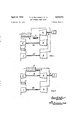
GAS TURBINE POWER PLANT M FIG-.5.
FIG.6.
INVENTORS Lf Onwm/. MALL/M50 I W/u/AM 56410 lie/c [En l5 ATTORNEYS Patented Apr. 20, 1954 GAS TURBINE POWER PLANT Dennis H. Mallinson, Fleet, and William G. E. Lewis,- Farnborough, England, assignors to Power Jets (Research and Development) Limited, London, England, a British company Application October 24, 1949, Serial- No. 123,162
Claims priority, application Great Britain November 2, 1948 3 Claims. (01. 6039.16)
This invention relates to a gas turbine plant of the kind which supplies power to a shaft, and is concerned, in particular, with improving the performance of such plant of this kind as is required to produce widely varying power outputs at widely varying shaft speeds, but also provides for an improved performance in plant of this'kind which is required to produce widely varying power at a constant shaft speed.
It is common, in a gas turbine power plant, to provide a heat exchanger to transfer heat from the working fluid-after expansion to that working fluid which is-about to be heated by combustion of fuel, so conserving heat which would otherwise be rejected. Thus, considered purely from the theoretical aspect, the. maximum tempera ture of the operating cycle of a plant having a heat exchanger may be raised indefinitely to give higher plant efficiencies, whereas, to raise the maximum cycletemperature of a planthaving no heat exchanger may result in poorer efficiencies, since a proportionately greater amount of heat may be rejected in the expanded working fluid at a higher maximum cycle temperature than at a lower maximum cycle temperature. In either case a practical limitation is imposed on the maximum cycle temperature by the ability of the material of the turbine blades, to withstand such temperature. Itmay, therefore, be stated, for gas turbine power planthaving adequateprovision for heat exchange generally (but, for plant having, no heat exchange, only in comparatively exceptional, cases, unless alternative means for promoting heat conservation are provided), that the maximum. cycle temperature should desirably be maintained, at all power outputs, substantiallyconstant at a value closeto the maximum temperature which. the. turbine blades can withstand, since a deviation from this condition at any power output within the required range, would result, in the case of a decreased maximum cycle temperature, in a loss in efiiciency at that power, and in the case of. an increased maximum cycle temperature, in dam.- age to the turbine blading; in either case, therefore, the effect is. detrimental to theperformance of the plant.
However, among the known arrangements of gas turbine power plant, whose performance would benefit by the satisfaction of the foregoing condition, many exhibit a tendency, when their power output is decreased progressively from its optimum value, to a progressively increasing, or decreasing maximum cycle tempera.
ature.
This characteristic is attributable to the requirement, usual in all normal applications, for.
a definite relationship between the power output and the shaft speedas imposedby the nature of the load, but is also inherent in the arrangement-ofthe components of the plant. Moreover, in many cases, the plant i incapable of producing widely varying loads as the imposed speed limitations, together with theplantarrangement,
are such as to cause instability in the flow of the working fluid in thecomponentsof' the plant.
In isolated cases however, the particular speed to power output relationship imposed on a plant may be favourable inthat the maximum-cycle temperature at varying power outputs does not vary greatly throughout. a useful powerv range. One such example occurs in the case of a known plant arrangement (to bedescribedhereinafter) when operating to produce varying powers at a constant shaft speed: the maximum cycle temperature, however, even in this case, falls tosome extent with decreasing power output, and theknownplant arrangement does not,
therefore, constitute the best possible for the speed to power output relationship imposed. In cases where a power output to-speed relationship of a difierent nature isrequiredv (as, for example, in the application of gas turbine plant to marine propulsion), even less success has been achieved, and known plant arrangements have, in general,
power output ranges under theseconditionswhich.
improved plant it will readily be appreciated that, in order to avoid speedlimitations imposed by the load being reflected in compressor performances, the output power-producing turbine stages should desirably berotationally independent of, the compressor-driving turbine stages.
A lessv obvious consideration, however, from-the realisationof which the invention springs, is that the maximum cycle. temperature characteristic .92 Zizwiiil: 1. 1.5; r.
of any gas turbine power plant at varying power outputs is influenced in a particular manner by the relationship between the pressure range of the output power-producing turbine stages and the pressure range of the compressor-driving turbine stages.
If, for example, a turbine system be considered in which two or more stages arranged in series with respect to fluid flow are designed to accommodate a given overall pressure or heat drop, each stage being arranged to accommodate a predetermined proportion of that pressure drop, it is found, when the system operates at a lower overall pressure or heat drop than that for which it is designed, that a disproportionate adjustment occurs in the pressure drop accommodated by each stage, the effect in general being that the proportion of the total pressure drop accommodated by the higher pressure stages increases while the proportion accommodated at the lower pressure stages decreases with decreasing overall pressure drop with a corresponding redistribution of the overall heat drop.
Further, if such a turbine system be designed as part of a plant in which any one, or combination of the turbine stages supplies the work for compression, it follows that, in order to produce from the compressor-driving stages a power output which bears a given relationship to their designed power output (i. e. for a given part-load compressor turbine output) the overall heat drop required varies according to the range of the heat or pressure drop of the compressor-driving turbine stages in relation to the overall heat or pressure drop. Thus, if the work for compression is derived from the heat or pressure drop in 'the lower, or in the higher pressure turbine stages, its proportion of the overall heat drop will respectively decrease or increase with a decrease in that overall heat drop. I
If two plants are now considered, each designed with the same total heat drop in the turbine stages for a supposed full-load power output and having a similar proportion of this heat drop devoted to compressor-driving turbine stages, at the high pressure end of the expansion in one case, and at the low pressure and of the expansion in the other, it will be apparent that, in order to produce an identical part-load power output from the compressor-driving turbine stages in each case, the part load overall heat drop required will be less in the first case than in the second. Or, if it is assumed that the two plants have a similar maximum cycle temperature at the full-load power output, the part-load maximum cycle temperature required in the first case will be lower than that required in the second case. It will be appreciated therefore that, between the two extremes represented by the two plants considered, an infinite number of plants may be postulated, each having similar full-load power outputs and corresponding maximum cycle temperature but differing in the location of their compressor-driving turbine stages with respect to the overall expansion and consequently requiring varying maximum cycle temperatures for a similar partload compressor turbine power output. Now supposing that the range covered by these varying part-load maximum cycle temperatures includes the common full-load maximum cycle temperature, then, in one particular plant, the condition that the maximum cycle temperature be constant at both the full-load and at the given partcondition is satisfied at any part-load (Within a desired range) by that particular plant, then the latter would constitute the most favourable basis for the design of a practical plant arrangement of the kind under consideration.
In pursuing such a possibility, an investigation of a general nature of such plant based on the foregoing considerations has led to the conclusion that a plant in which turbine stages producing the useful external power are located near the high pressure end of the expansion will tend to have a rising maximum cycle temperature with decreasing power output, while a plant in which the output power-producing turbine stages are near the low pressure end of the expansion will tend to have a falling maximum cycle temperature-with decreasing power output. In general it ,is found that the power-producing turbine stages should be toward the high pressure end of the expansion rather than the low pressure end in order that the maximum cycle temperature be maintained substantially constant at varying power outputs.
Accordingly the invention proposes a gas turbine plant supplying useful shaft power comprising both compressor-driving turbine stages and other turbine stages producing substantially the whole of the useful power output of the plant, in which the pressure drop of the working fluid in passing from the highest to the lowest pressure compressor-driving turbine stages is substantially the total pressure drop in the working fluid in the cycle of the plant, while the output power-producing turbine stages are arranged for rotation independently of the compressor-driving turbine stages and, in respect of the flow of working fluid, are in parallel or in intermediate series with certain of those stages such that they opcludes the case when the respective pressure ranges are co-terminous at their upper limits.
The invention may be considered to be of particular interest in its application to a plant having a heat exchanger, but it may also be applied, in appropriate cases, to plant having means al-,'
ternative to heat exchangers which conserve heat in a similar manner, or to plant having no such provision whatsoever.
Figure 1 is a schematic view of a gas turbine power plant according to the present invention;
Figure 2 is a schematic view of a prior art gas turbine power plant;
Figures 3 and 4 are graphs on which comparative performance data of the plants of Figures 1 and 2 are plotted;
Figure 5 is a schematic view of a gas turbin plant according to the present invention in which there is a group of power turbines in parallel with a group of compressor turbines; and
Figure 6 is a view similar to Figure 5 of a power plant in which the power turbine is in series with a group of compressor driving turbines.
The embodiment shown in Figure 1 is preferred because it represents the most simple arrangement of components which will achieve the desired result. compressor 1 and passes therefrom to a high pressure compressor 2 by way of an inter-cooler Air is inspired by the low pressure compressor '2"-the air passes through 'a heat ex-v changer 4 -and to-combustion apparatus 5 whence the-products of combustion are divided into two streams one of which supplies a power turbinet Whichis coupled to the load-I l bythe' shaft} and the-other passes to a turbine"! which is coupled by a shaft It) to the high pressure compressor 2:1
The gases, on leaving the output power turbine 6 andthe high pressure compressor=driving turbine 9, are reunited andpass to a low pressure turbine II which is coupled by the shaft I2 to the low pressure compressor I thegases Jeaving-the low pressure turbine pass before; being exhausted through the heat exchanger 4 w-here some-heat is. imparted to combustionair; V
Thus the. output power turbine coincides; in respect of its pressure range, with the upper part of the compressor turbine pressure range, whilst being rotationally independent of the compressors.
In the known plant arrangement illustrated in Figure 2, air is inspired by a low pressure com pressor i and passes therefrom to a high pressure compressor 2 by way of an inter-cooler 3 (optional) Thereafter the air passes through a heat exchanger 4 to a combustion chamber 5, the
combustion products from which pass through a, high pressure turbine 6 which drives through the shaft 8 both the high pressure compressor 2 and a load 1, and then through a low pressure turbine 9 which is coupled by the shaft to the low pressure compressor I. The gases are finally exhausted through the heat exchanger 4. This plant arrangement, as has been remarked previously, is noteworthy for its performance when the high pressure rotor shaft 8 rotates at a constant speed at varying power outputs.
For the purpose of comparison, two plants have been considered, according to Figures 1 and 2 respectively, each being supposed to have an overall pressure ratio of 12:1 and a maximum cycle temperature of 1050 K. at the design condition. The performance of each plant has been considered when driving a varying load, in one case at constant speed, and in another case where the speed is related to the load by a propeller law. Figure 3 shows the curves of maximum temperature in degrees Kelvin (ordinates) plotted against load (abscissa) and Figure 4 shows the curves of percentage thermal efficiency (ordinates) plotted against load (abscissa) for each plant at each condition; part-loads are in each case expressed as fractions of the full-load? In the case of the plant according to the invention (as in Figure l) the curves for constant speed and propeller law operation coincide and are represented in Figures 3 and 4 by the full line curves marked lcv. From Figure 3 it is seen that the maximum temperature at all loads above per cent. of full-load is very close to its value at the design point A; and from Figure 4 the thermal efiiciency can be seen to be very high at all but the lightest loads. The perform ance of the plant according to Figure 2, when operating on the propeller law, is shown by.
dotted-line curves marked 2V in Figures 3 and 4. The maximum temperature rises rapidly with falling load, and the curve ceases at the point B, i. e. at approximately 80 per cent. full-load, due to compressor instability resulting from the imposed speed conditions; the thermal efficiency rises, of course, with the rising maximum temperature. When the same plant (Figure 2) opf eratesat constant speed, the performance curves termittent line curves in Figuresn3k'andz-4zmarked 2c. The 'maximum temperature-t'however, falls quite rapidly'from theivalueat: the design point A:;.: the; resultant :effect' on the efllciency is! also quite pronouncedwhen .comparedrwith:thexcurve lcu for. the plant accordingto the invention.
. From the" foregoing comparison it: is apparent that, the plant according. to the invention, additionfto" providing forgood: efficiencies at; all usefulzloads; when the speed, is" required, to: also-constitutes an improvement. over known plant: for constant speedapplications, requiring for-thepurpose: only." that the power output turbinezbe provided withconstant speed' governing;
Although the plant as shown. in: Figurei'1;:-is consideredideally;- suited to applications as *di"-' verse as; marine propulsion an'delectricity generation, and, indeed, to most normal applications, it may, in some cases, be advantageous to use a plant substantially similar, but provided with separate combustion chambers to each of the power and high pressure compressor turbines, and/or a reheat combustion chamber immediately upstream of the low pressure compressor turbine.
Other embodiments of the invention might include arrangements having four or more turbines l3, l4, I5 and I6, see Figure 5, with a correspondingly increased number of compressor stalges l1, I8, I 9 and 20 to allow greater selectivity in the location of the power turbine 2| or turbines 2| and 22 within the overall expansion, either in series (not shown) or in parallel, as shown, with compressor turbine stages l3, l4, I5 and I 6.
In the embodiment of Figure 6 there are three compressor stages 23, 24 and 25 each driven by one of a corresponding number of turbine stages 26, 21, and 28, the high, intermediate and low pressure turbines driving respectively the high, intermediate and low pressure compressors, and a power turbine 29 in series with and situated between the high and intermediate pressure turbines. It is thought that such an embodiment could be designed togive a performance comparable with that of the preferred embodiment, of Figure 1, although, of course, its additional rotor makes it more complicated.
We claim:
1. A gas turbine power plant for supplying usefull shaft power comp-rising compressors connected to receive air from atmosphere, av plurality of rotationally independent turbines in driving connection with said compressors, turbine means rotationally independent of said compressor-driving turbines and constituting the power-output turbine means from which substantially the whole useful power-output; of the plant may be drawn, and heating means connected to receive compressed air from the compressors and to supply hot gas as working fluid to said turbines and said turbine means, wherein said compressor-drivin turbines includ a plurality of turbines connected in series with respect to the flow of working fluid therethrough, the first of the series being connected directly to the said heating means and the last connected to exhaust to atmosphere, said output powerproducing turbine means being connected to exhaust through at least the last of said series and to receive working fluid at a point differing less in pressure from the maximum pressure in said series than the exhaust pressure of said output- 7 power-producing turbines means difiers from atmosuheric" pressure. 1
'2. A gas turbine power plant according to claim 1, wherein said output power producing turbine means is connected to receiv working fluid directly from said heating means.
3. A gas turbine power plant comprising a low pressure compressor for compressing air from the atmosphere, 'a high pressure compressor rotationally independent of said low pressure compressor for receiving air from said low pressure compressor, heater means for receiving and heating air from said high pressure compressor, at least two rotationally independent high pressure turbines each connected directly to said heater means for receiving as working fluid the heated products therefrom of which high pressure turbines at least one is drivingly connected only 8 to said high pressure compressor and another provided only the power output of the plant, and at least one low pressure turbine rotationally independent of said high pressure turbines and receiving substantially all the working fluid exhausted therefrom, said low pressure turbine being drivingly connected only to said low pressure compressor.
References Cited in the file Of this patent UNITED STATES PATENTS,
2,469,238 1 Newton May 3, 1949
Publications (1)
| Publication Number | Publication Date |
|---|---|
| US2675673A true US2675673A (en) | 1954-04-20 |
Family
ID=3440210
Family Applications (1)
| Application Number | Title | Priority Date | Filing Date |
|---|---|---|---|
| US2675673D Expired - Lifetime US2675673A (en) | Gas turbine power plant |
Country Status (1)
| Country | Link |
|---|---|
| US (1) | US2675673A (en) |
Cited By (14)
| Publication number | Priority date | Publication date | Assignee | Title |
|---|---|---|---|---|
| US5081832A (en) * | 1990-03-05 | 1992-01-21 | Rolf Jan Mowill | High efficiency, twin spool, radial-high pressure, gas turbine engine |
| US5119624A (en) * | 1989-06-15 | 1992-06-09 | Rolls-Royce Business Ventures Limited | Gas turbine engine power unit |
| US5377483A (en) * | 1993-07-07 | 1995-01-03 | Mowill; R. Jan | Process for single stage premixed constant fuel/air ratio combustion |
| US5572862A (en) * | 1993-07-07 | 1996-11-12 | Mowill Rolf Jan | Convectively cooled, single stage, fully premixed fuel/air combustor for gas turbine engine modules |
| US5613357A (en) * | 1993-07-07 | 1997-03-25 | Mowill; R. Jan | Star-shaped single stage low emission combustor system |
| US5628182A (en) * | 1993-07-07 | 1997-05-13 | Mowill; R. Jan | Star combustor with dilution ports in can portions |
| US5638674A (en) * | 1993-07-07 | 1997-06-17 | Mowill; R. Jan | Convectively cooled, single stage, fully premixed controllable fuel/air combustor with tangential admission |
| US5924276A (en) * | 1996-07-17 | 1999-07-20 | Mowill; R. Jan | Premixer with dilution air bypass valve assembly |
| US6220034B1 (en) | 1993-07-07 | 2001-04-24 | R. Jan Mowill | Convectively cooled, single stage, fully premixed controllable fuel/air combustor |
| US6735951B2 (en) * | 2002-01-04 | 2004-05-18 | Hamilton Sundstrand Corporation | Turbocharged auxiliary power unit with controlled high speed spool |
| US6925809B2 (en) | 1999-02-26 | 2005-08-09 | R. Jan Mowill | Gas turbine engine fuel/air premixers with variable geometry exit and method for controlling exit velocities |
| WO2008153516A1 (en) * | 2007-05-25 | 2008-12-18 | Carrier Corporation | Rankine system with gravity-driven pump |
| CN103161529A (en) * | 2011-12-12 | 2013-06-19 | 邵再禹 | Closed circulation electricity generation method canceling working medium backwash pump |
| CN111911287A (en) * | 2019-05-09 | 2020-11-10 | 三菱重工业株式会社 | Turbocharging cluster gas turbine system and starting method thereof |
Citations (5)
| Publication number | Priority date | Publication date | Assignee | Title |
|---|---|---|---|---|
| US2091998A (en) * | 1934-02-24 | 1937-09-07 | Milo Ab | Gas turbine system |
| US2245954A (en) * | 1937-01-25 | 1941-06-17 | Rateau Soc | Gas turbine engine plant |
| US2280765A (en) * | 1935-12-09 | 1942-04-21 | Anxionnaz Rene | Gas turbine thermic engine |
| US2418911A (en) * | 1944-04-28 | 1947-04-15 | Elliott Co | Gas turbine cycle |
| US2469238A (en) * | 1947-08-28 | 1949-05-03 | Westinghouse Electric Corp | Gas turbine apparatus |
-
0
- US US2675673D patent/US2675673A/en not_active Expired - Lifetime
Patent Citations (5)
| Publication number | Priority date | Publication date | Assignee | Title |
|---|---|---|---|---|
| US2091998A (en) * | 1934-02-24 | 1937-09-07 | Milo Ab | Gas turbine system |
| US2280765A (en) * | 1935-12-09 | 1942-04-21 | Anxionnaz Rene | Gas turbine thermic engine |
| US2245954A (en) * | 1937-01-25 | 1941-06-17 | Rateau Soc | Gas turbine engine plant |
| US2418911A (en) * | 1944-04-28 | 1947-04-15 | Elliott Co | Gas turbine cycle |
| US2469238A (en) * | 1947-08-28 | 1949-05-03 | Westinghouse Electric Corp | Gas turbine apparatus |
Cited By (21)
| Publication number | Priority date | Publication date | Assignee | Title |
|---|---|---|---|---|
| US5119624A (en) * | 1989-06-15 | 1992-06-09 | Rolls-Royce Business Ventures Limited | Gas turbine engine power unit |
| US5081832A (en) * | 1990-03-05 | 1992-01-21 | Rolf Jan Mowill | High efficiency, twin spool, radial-high pressure, gas turbine engine |
| US6220034B1 (en) | 1993-07-07 | 2001-04-24 | R. Jan Mowill | Convectively cooled, single stage, fully premixed controllable fuel/air combustor |
| US5377483A (en) * | 1993-07-07 | 1995-01-03 | Mowill; R. Jan | Process for single stage premixed constant fuel/air ratio combustion |
| US5477671A (en) * | 1993-07-07 | 1995-12-26 | Mowill; R. Jan | Single stage premixed constant fuel/air ratio combustor |
| US5481866A (en) * | 1993-07-07 | 1996-01-09 | Mowill; R. Jan | Single stage premixed constant fuel/air ratio combustor |
| US5572862A (en) * | 1993-07-07 | 1996-11-12 | Mowill Rolf Jan | Convectively cooled, single stage, fully premixed fuel/air combustor for gas turbine engine modules |
| US5613357A (en) * | 1993-07-07 | 1997-03-25 | Mowill; R. Jan | Star-shaped single stage low emission combustor system |
| US5628182A (en) * | 1993-07-07 | 1997-05-13 | Mowill; R. Jan | Star combustor with dilution ports in can portions |
| US5638674A (en) * | 1993-07-07 | 1997-06-17 | Mowill; R. Jan | Convectively cooled, single stage, fully premixed controllable fuel/air combustor with tangential admission |
| US5765363A (en) * | 1993-07-07 | 1998-06-16 | Mowill; R. Jan | Convectively cooled, single stage, fully premixed controllable fuel/air combustor with tangential admission |
| US5924276A (en) * | 1996-07-17 | 1999-07-20 | Mowill; R. Jan | Premixer with dilution air bypass valve assembly |
| US6925809B2 (en) | 1999-02-26 | 2005-08-09 | R. Jan Mowill | Gas turbine engine fuel/air premixers with variable geometry exit and method for controlling exit velocities |
| US6735951B2 (en) * | 2002-01-04 | 2004-05-18 | Hamilton Sundstrand Corporation | Turbocharged auxiliary power unit with controlled high speed spool |
| WO2008153516A1 (en) * | 2007-05-25 | 2008-12-18 | Carrier Corporation | Rankine system with gravity-driven pump |
| US20100154421A1 (en) * | 2007-05-25 | 2010-06-24 | Carrier Corporation | Rankine system with gravity-driven pump |
| CN101765703B (en) * | 2007-05-25 | 2012-11-14 | 开利公司 | Rankine system with gravity-driven pump |
| CN103161529A (en) * | 2011-12-12 | 2013-06-19 | 邵再禹 | Closed circulation electricity generation method canceling working medium backwash pump |
| CN111911287A (en) * | 2019-05-09 | 2020-11-10 | 三菱重工业株式会社 | Turbocharging cluster gas turbine system and starting method thereof |
| JP2020183733A (en) * | 2019-05-09 | 2020-11-12 | 三菱重工業株式会社 | Turbo cluster gas turbine system and method of starting the same |
| US11319873B2 (en) * | 2019-05-09 | 2022-05-03 | Mitsubishi Heavy Industries, Ltd. | Turbo cluster gas turbine system and activation method thereof |
Similar Documents
| Publication | Publication Date | Title |
|---|---|---|
| US2675673A (en) | Gas turbine power plant | |
| US2078956A (en) | Gas turbine system | |
| US2219994A (en) | Gas turbine plant and regulating system therefor | |
| US3796045A (en) | Method and apparatus for increasing power output and/or thermal efficiency of a gas turbine power plant | |
| US3630022A (en) | Gas turbine engine power plants | |
| US4569195A (en) | Fluid injection gas turbine engine and method for operating | |
| US4858428A (en) | Advanced integrated propulsion system with total optimized cycle for gas turbines | |
| US2115338A (en) | Gas turbine system | |
| US2172910A (en) | Power plant | |
| US3500636A (en) | Gas turbine plants | |
| US4841721A (en) | Very high efficiency hybrid steam/gas turbine power plant wiht bottoming vapor rankine cycle | |
| US4753068A (en) | Gas turbine cycle incorporating simultaneous, parallel, dual-mode heat recovery | |
| US2675672A (en) | Schsrner | |
| US2298663A (en) | Gas turbine plant | |
| US3394265A (en) | Spinning reserve with inlet throttling and compressor recirculation | |
| JPS60156910A (en) | steam turbine equipment | |
| US2078958A (en) | Gas turbine system | |
| US2457594A (en) | Turbine compressor plant | |
| US2859954A (en) | Gas turbine plant for providing a continuous supply of hot compressed air | |
| US2407165A (en) | Method and means for improving power production in combustion turbines | |
| US2131781A (en) | Gas turbine system of the continuous combustion type | |
| US2312995A (en) | Gas turbine plant | |
| Mallinson et al. | The part-load performance of various gas-turbine engine schemes | |
| US3273340A (en) | Gas turbine powerplant having an extremely high pressure ratio cycle | |
| US2496407A (en) | Internal-combustion turbine plant |