US266725A - Two-wheeled vehicle - Google Patents
Two-wheeled vehicle Download PDFInfo
- Publication number
- US266725A US266725A US266725DA US266725A US 266725 A US266725 A US 266725A US 266725D A US266725D A US 266725DA US 266725 A US266725 A US 266725A
- Authority
- US
- United States
- Prior art keywords
- vehicle
- pole
- wheeled vehicle
- clamps
- axle
- Prior art date
- Legal status (The legal status is an assumption and is not a legal conclusion. Google has not performed a legal analysis and makes no representation as to the accuracy of the status listed.)
- Expired - Lifetime
Links
- 241000283086 Equidae Species 0.000 description 14
- 239000002184 metal Substances 0.000 description 6
- 239000007787 solid Substances 0.000 description 4
- 229910000831 Steel Inorganic materials 0.000 description 2
- 238000010276 construction Methods 0.000 description 2
- 230000000875 corresponding Effects 0.000 description 2
- 239000010985 leather Substances 0.000 description 2
- 239000000203 mixture Substances 0.000 description 2
- 239000010959 steel Substances 0.000 description 2
- 239000002023 wood Substances 0.000 description 2
Images

Classifications
-
- B—PERFORMING OPERATIONS; TRANSPORTING
- B60—VEHICLES IN GENERAL
- B60R—VEHICLES, VEHICLE FITTINGS, OR VEHICLE PARTS, NOT OTHERWISE PROVIDED FOR
- B60R3/00—Arrangements of steps or ladders facilitating access to or on the vehicle, e.g. running-boards
- B60R3/02—Retractable steps or ladders, e.g. movable under shock
Definitions
- Myimprovement consists, first, in so constructing the shafts or thills of the vehicle that they can be-lengthened or shortened at pleasure-lengthened to make what is called a kicker when the horse is hitched far enough from the vehicle to prevent his doing any damage should he kick, or to shorten them for ordinary driving purposes or a pony; sec 0nd, in so constructing the vehicle that the shafts may be removed and a pole or tongue attached to form a two-horse vehicle with two wheelsa two-horse sulky; third, a novel construction of springs, body, and seat for a vehicle.
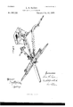
- Figure 1 represents a side elevation of my improved vehicle; Fig. 2, a top plan view.
- Fig. 3 shows the arrangement for attaching the pole and making a twohorse vehicle.
- Figs. 4 and 5 show the clamps and bolt for fastening the pole in place.
- Fig. (i is a modified form for a two-horse sulky.
- axle-brackets O C are attached directly and rigidly to the. axle of the vehicle, as shown at A, Fig. 1, by means of the metal braces a a, between which they are bolted.
- the heads of these braces pass through the end of the brace B, and are firmly secured by nuts I) Z), the other end of the brace B being firmly bolted to the under side of the shaft or bracket 0 at 0 c 0, thus forming a firm, rigid connection with the axle.
- brackets (J O are provided with clamps D D, of any suitable form, which are either stationary or removable, and may be made, as shown in the drawings, in the shape of a staple, with a plate, (I, litting over both arms of the staple and screwed up tight by nuts.
- clamps D D of any suitable form, which are either stationary or removable, and may be made, as shown in the drawings, in the shape of a staple, with a plate, (I, litting over both arms of the staple and screwed up tight by nuts.
- clamps D may be so arranged that the shafts can be attached to the bracket either on the top or bottom or side, as is most convenient, and different pairs of shafts of variouslengths may be inserted.
- the pole may be fastened in these clamps in any convenient way; but I prefer the manner shown in Figs. 4 and 5.
- There the clamps are made slightly tapering toward the rear, so that the farther the pole is inserted the tighter it is held.
- the rear clamp, G has a hole in the rear plate, through which passes a bolt, H, with a screwthread which tits into a corresponding thread in the rear end of the pole, which may be provided with a metal plate or socket, with an internal screw-thread to receive the forward end of the bolt H.
- the bolt H is turned and screwed into the end of the pole, the pole is drawn tighter and tighter into the clamps G and G, so as to make a perfectly-rigid joint or connection.
- 011 the axle-brackets O U are fastened clevis-loops I I. These may be very conveniently made of the forward end of the brace B, as shown in the drawings.
- aspring bar or brace, L ofwood, to the upper ends of which is attached the seat M, and in order to elevate the seat to a proper height and to give it additional spring these bars L L are made to rest on cushions of rubber N, placed at a proper distance from the sides of the brackets O on each side, steel springs P, the rear ends ofwhich are fastened to the bottom of the seat M orthe bars L.
- These springs may be made of any desired strength and shape, and by fastening to them narrow slat-s of wood R R It a strong and almost solid bottom is made for the vehicle back of the platform F, over which a rug or flexible board may be fastened.
- the double-tree is attached to the ends of the brackets or clamp G in the usual manner, and the seat is supported in any convenient way-as by braces-from the axle and pole shown in Fig. 6. By this arrangement no springs are used and the vehicle and horses move absolutely together.
- axle-brack cts G arranged as described, and provided with the clamps D D for attaching the shafts properly, in combination with the cross-piece F, brackets G G, and bolt H, for attaching apole.
- the springs P P having their front ends bolted firmly to the cross-beam F and their rear ends bolted firmly to the bars L or the bottom of the seat, as
Landscapes
- Engineering & Computer Science (AREA)
- Mechanical Engineering (AREA)
- Automatic Cycles, And Cycles In General (AREA)
Description
(No Model.) 2 SheetsSheet 1.
' L. G. SAYRE.
. TWO WHEELED VEHICLE.
210.266.725. Patented O0-t.31,1882.
21W um;
(No Model.) 2 Sheets-Sheet 2.
L. G. SAYRE.
TWO WHEELED VEHICLE.
No. 266,725. Patented Oct. 31, 1882.
UNTTED STATES LEXVIS G. SAYRE, OF MOUNT HEALTHY, OHIO.
TWO-WHEELED VEHICLE.
SPECIFICATION forming part of Letters Patent No. 266,725, dated. October 31, 1882. Application filed May 1, 1382. (No model.
To all whom it may concern:
Be it known that I, LEWIS G. SAYRE, a citizen of the United States, residing in the town of Mount Healthy, Hamilton county, Ohio, have invented certain new and useful Improvements in Vehicles, of which the following is a specification.
Myimprovement consists, first, in so constructing the shafts or thills of the vehicle that they can be-lengthened or shortened at pleasure-lengthened to make what is called a kicker when the horse is hitched far enough from the vehicle to prevent his doing any damage should he kick, or to shorten them for ordinary driving purposes or a pony; sec 0nd, in so constructing the vehicle that the shafts may be removed and a pole or tongue attached to form a two-horse vehicle with two wheelsa two-horse sulky; third, a novel construction of springs, body, and seat for a vehicle.
In the accompanying drawings, Figure 1 represents a side elevation of my improved vehicle; Fig. 2, a top plan view. Fig. 3 shows the arrangement for attaching the pole and making a twohorse vehicle. Figs. 4 and 5 show the clamps and bolt for fastening the pole in place. Fig. (i is a modified form for a two-horse sulky.
The axle-brackets O C are attached directly and rigidly to the. axle of the vehicle, as shown at A, Fig. 1, by means of the metal braces a a, between which they are bolted. The heads of these braces pass through the end of the brace B, and are firmly secured by nuts I) Z), the other end of the brace B being firmly bolted to the under side of the shaft or bracket 0 at 0 c 0, thus forming a firm, rigid connection with the axle. These brackets (J O are provided with clamps D D, of any suitable form, which are either stationary or removable, and may be made, as shown in the drawings, in the shape of a staple, with a plate, (I, litting over both arms of the staple and screwed up tight by nuts. By means of these clamps, shafts or thills E E are attached to the vehicle, and by loosening the nuts which hold the plates d (l the thills may he pushed back and shortened or pulled out and lengthened, as is desired; and by simply screwing up the nuts are again made fast and firm. The
clamps D may be so arranged that the shafts can be attached to the bracket either on the top or bottom or side, as is most convenient, and different pairs of shafts of variouslengths may be inserted. There is bolted to these brackets O O a board or platform, F, and on the center of this platform are provided clamps G and G for a pole or tongue to be used when it is desired to drive two horses, the thills of course being removed. The pole may be fastened in these clamps in any convenient way; but I prefer the manner shown in Figs. 4 and 5. There the clamps are made slightly tapering toward the rear, so that the farther the pole is inserted the tighter it is held. The rear clamp, G, has a hole in the rear plate, through which passes a bolt, H, with a screwthread which tits into a corresponding thread in the rear end of the pole, which may be provided with a metal plate or socket, with an internal screw-thread to receive the forward end of the bolt H. As the bolt H is turned and screwed into the end of the pole, the pole is drawn tighter and tighter into the clamps G and G, so as to make a perfectly-rigid joint or connection. 011 the axle-brackets O U are fastened clevis-loops I I. These may be very conveniently made of the forward end of the brace B, as shown in the drawings. To these are attached by leather or metal straps the single-trees J J when two horses are used, no double-tree being used at all. lly this means, when the team makes a turn or curve, the horse on the outer side of the curve pulls the wheel on that side round by a direct draft on it, and of course pulls the pole around, there being no strain on the pole whatever. This direct draft upon either side of the vehicle facilitates making curves, and is of value when horses are driven at a fast speed. When one horse is used with the thills the traces or tugs are attached directly to the clevis loops 1 I and a single-tree dispensed with.
In front of the platform F, on each side of the vehicle, there is pivoted by a link, 'K, or in any suitable manner, aspring bar or brace, L, ofwood, to the upper ends of which is attached the seat M, and in order to elevate the seat to a proper height and to give it additional spring these bars L L are made to rest on cushions of rubber N, placed at a proper distance from the sides of the brackets O on each side, steel springs P, the rear ends ofwhich are fastened to the bottom of the seat M orthe bars L. These springs may be made of any desired strength and shape, and by fastening to them narrow slat-s of wood R R It a strong and almost solid bottom is made for the vehicle back of the platform F, over which a rug or flexible board may be fastened.
It is sometimes desirable when horses are speeded very fast to make the vehicle as solid as possible and to take away all spring which might att'ect the motions of the horse or horses in the slightest degree. In that casev the rubber springs N are taken out, and, if necessary, thespringPremoved and the bars LLstrapped tight down on the platform F; or when two horses are to be driven at a high speed the axle-brackets O (J are made to converge at a point equally distant from both wheels in front of the axle, as shown in Fig. 6. The forward ends are provided with a clamp, G by which they are firmly fastened together and through which the tongue or pole passes, and its rear end bolted or clamped to the axle, as shown at Z, Fig. 6. The double-tree is attached to the ends of the brackets or clamp G in the usual manner, and the seat is supported in any convenient way-as by braces-from the axle and pole shown in Fig. 6. By this arrangement no springs are used and the vehicle and horses move absolutely together.
Having thus described my invention, what I claim as new, and desire to secure by Letters Patent, is-
1. In a two-wheeled vehicle, the axle-brack cts G 0, arranged as described, and provided with the clamps D D for attaching the shafts properly, in combination with the cross-piece F, brackets G G, and bolt H, for attaching apole. I
2 The clevis-loopsII, arranged as described, for attaching either the traces or the singletrees J J, as and for the purpose described.
3. In a two-wheeled vehicle, the springs P P, having their front ends bolted firmly to the cross-beam F and their rear ends bolted firmly to the bars L or the bottom of the seat, as
and for the purpose described.
LEVIS G. SAYRE.
Witnesses:
J ERE '1. TwoHrG, Gus. A. MEYER.
Publications (1)
| Publication Number | Publication Date |
|---|---|
| US266725A true US266725A (en) | 1882-10-31 |
Family
ID=2335976
Family Applications (1)
| Application Number | Title | Priority Date | Filing Date |
|---|---|---|---|
| US266725D Expired - Lifetime US266725A (en) | Two-wheeled vehicle |
Country Status (1)
| Country | Link |
|---|---|
| US (1) | US266725A (en) |
-
0
- US US266725D patent/US266725A/en not_active Expired - Lifetime
Similar Documents
| Publication | Publication Date | Title |
|---|---|---|
| US266725A (en) | Two-wheeled vehicle | |
| US458668A (en) | Training-wagon | |
| US721525A (en) | Draft device for harvesters. | |
| US293751A (en) | Wagon-tongue support | |
| US688894A (en) | Front gear for vehicles. | |
| US511092A (en) | Sulky | |
| US518507A (en) | Sulky | |
| US239885A (en) | terbttsh | |
| US407715A (en) | George beebe | |
| US789542A (en) | Shifting attachment for vehicle-shafts. | |
| US296930A (en) | Teebitoey | |
| US463923A (en) | Vehicle-shaft | |
| US303738A (en) | Two wheeled vehicle | |
| US361112A (en) | Road-cart | |
| US269285A (en) | Two-wheeled vehicle | |
| US334999A (en) | Draft-gouplil | |
| US528927A (en) | foote | |
| US383207A (en) | Two-wheeled vehicle | |
| US267140A (en) | Sulky | |
| US508330A (en) | Adolph meyerhoff | |
| US409346A (en) | Two-wheeled vehicle | |
| US457600A (en) | Office | |
| US388704A (en) | Levaist millee | |
| US809328A (en) | Draft-gear for vehicles. | |
| US251345A (en) | Thill-coupling |