US2655837A - Automatic gun - Google Patents
Automatic gun Download PDFInfo
- Publication number
- US2655837A US2655837A US774310A US77431047A US2655837A US 2655837 A US2655837 A US 2655837A US 774310 A US774310 A US 774310A US 77431047 A US77431047 A US 77431047A US 2655837 A US2655837 A US 2655837A
- Authority
- US
- United States
- Prior art keywords
- cartridge
- bolt
- barrel
- receiver
- chamber
- Prior art date
- Legal status (The legal status is an assumption and is not a legal conclusion. Google has not performed a legal analysis and makes no representation as to the accuracy of the status listed.)
- Expired - Lifetime
Links
- 230000007246 mechanism Effects 0.000 description 60
- 238000010304 firing Methods 0.000 description 22
- 238000010276 construction Methods 0.000 description 6
- 230000000994 depressogenic effect Effects 0.000 description 6
- 125000006850 spacer group Chemical group 0.000 description 6
- 239000007789 gas Substances 0.000 description 5
- 230000000881 depressing effect Effects 0.000 description 3
- 210000003811 finger Anatomy 0.000 description 3
- 230000010355 oscillation Effects 0.000 description 3
- 230000035939 shock Effects 0.000 description 3
- 238000004880 explosion Methods 0.000 description 2
- 210000003414 extremity Anatomy 0.000 description 2
- 238000007689 inspection Methods 0.000 description 2
- 230000000149 penetrating effect Effects 0.000 description 2
- 230000002028 premature Effects 0.000 description 2
- 230000000284 resting effect Effects 0.000 description 2
- 230000008878 coupling Effects 0.000 description 1
- 238000010168 coupling process Methods 0.000 description 1
- 238000005859 coupling reaction Methods 0.000 description 1
- 230000006378 damage Effects 0.000 description 1
- 230000000694 effects Effects 0.000 description 1
- 210000004247 hand Anatomy 0.000 description 1
- 239000002184 metal Substances 0.000 description 1
- 230000004048 modification Effects 0.000 description 1
- 238000012986 modification Methods 0.000 description 1
- 229920000136 polysorbate Polymers 0.000 description 1
- 230000008439 repair process Effects 0.000 description 1
- 230000000452 restraining effect Effects 0.000 description 1
- 238000004904 shortening Methods 0.000 description 1
- 239000013589 supplement Substances 0.000 description 1
- 210000003813 thumb Anatomy 0.000 description 1
Images


Classifications
-
- F—MECHANICAL ENGINEERING; LIGHTING; HEATING; WEAPONS; BLASTING
- F41—WEAPONS
- F41A—FUNCTIONAL FEATURES OR DETAILS COMMON TO BOTH SMALLARMS AND ORDNANCE, e.g. CANNONS; MOUNTINGS FOR SMALLARMS OR ORDNANCE
- F41A9/00—Feeding or loading of ammunition; Magazines; Guiding means for the extracting of cartridges
- F41A9/29—Feeding of belted ammunition
Definitions
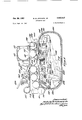
- AUTouATIc GUN Filed sept. 1e, 1947 a sheets-sheet ff @45% 5f a Zf/J @a d 45 f y i 4 .f a ,a f 515 www. ha, x. a M m l 4, TVM j @j W H m T r w f l f/ w m. f 1 4 Z w a 4 j L 5% f 0t 20, 1953 M. M. JOHNSON, JR 2,655,837
- This invention relates to firearms of the rapid firing portable type such as is shown and described in United States Patents Nos. 2,094,156; 2,146,743; 2,215,470; and 2,383,487, granted upon applications filed under my name, and the objects of the present invention are to improve the aforesaid gun in several aspects to provide for smoother operation and greater efficiency without sacrificing any of the features and advantages of that gun.
- these objects include the provision of improved cartridge-feeding means, which is simple and economical in construction, which is reliable and durable in use, which can be assembled and disassembled with ease, and which is especially suitable for supplying cartridges to the gun by way of a disintegratable type of cartridge-feed belt; of improved breech bolt locking means to insure locking of the bolt in a closed position; of improved ejector construction to prevent destruction of the extractor during ejection; and of improved flring-pin mechanism to prevent premature firing.
- the gun is of the recoiling barrel type including a receiver, a barrel mounted for recoil and counter-recoil therein, the barrel having a breech and cartridge chamber and a bolt and bolt chamber, the latter being in the receiver. Below the bolt chamber there is detachably secured.
- a cartridge feed-in mechanism arranged intermittently to feed a belt of cartridges inwardly from one side of the gun to present one cartridge at a time into a position to be rammed by the bolt into the cartridge chamber.
- the feeding mechanism is motivated, in accordance with one aspect of this invention, by the recoil of the barrel in contrast to the conventional use of the bolt for this purpose, thus providing for more positive operation because of the greater weight of the barrel and for use of this type of feed-in, in light-weight guns wherein the kinetic energy imparted to the bolt is not sufficient to actuate the feed mechanism.
- it is contemplated to supplement the energy of the barrel in recoil because its recoil is comparatively short with some of the energy of the gases generated by the explosion of the cartridge by conducting part of these gases to a piston-like member on the barrel, thereby to impart additional force to the recoil of the barrel.
- a cylinder is formed on the receiver, gas is supplied thereto from the barrel through a small aperture in the wall thereof, and a piston is formed on the barrel which fits closely into the cylinder.
- the feed mechanism includes pairs of feed pawls operable successively by the recoil of the barrel to engage cartridges in the cartridge belt and to move them one at a time onto an elevator below the bolt chamber, each pair of pawls after moving a cartridge a predetermined amount being retracted beneath the succeeding cartridge to engage the rear side thereof for the next forward feeding movement.
- a narrow passage in the bolt chamber allows a portion of the cartridge on the elevator to project into the path of the bolt.
- the feed mechanism is housed in a feed mechanism housing, and for ease of assembly the latter is slidably mounted in the receiver in cooperating ways.
- the housing has an upper throat-like portion through which the cartridge belt is fed by the aforesaid pawls, the latter projecting upwardly into the throat from an enclosed lower portion in which the feed pawl operating mechanism is located.
- This operating mechanism is carried by a movable support therein which may be retracted within the housing to Withdraw the pawls from the feedthroat, thereby to clear the throat so that the cartridge belt may be removed.
- a retaining pawl in the top of the throat cooperates with the pawls normally to hold the belt against retrogression, and this, too, may be retracted to clear the throat.
- the aforementioned breech bolt has splines at its forward end which enter the breech block through spline-ways and is rotated to move the splines to a position between the spline-ways of the breech block, thereby to lock the bolt in breech-closing position.
- an independent, spring-loaded lock cooperable with a recess in the bolt opposite which it is brought by rotation of the bolt so that counter-rotation of the bolt is prevented.
- the lock may be manually lifted out of the recess to unlock the bolt or automatically removed therefrom by the combined recoil of the barrel and bolt.
- the breech bolt is hollow, that is. has a longitudinal passage therein in which there is situated a firing pin.
- a spring normally holds the nring pin withdrawn in the bolt so that when the bolt is in breech-closing position the firing pin does not project. Due to the fact that the forward movement of the bolt and iiring pin is rapid. when the bolt is brought to a sudden stop, momentum of the firing pin throws it forward in spite of the spring so that there might be an accidental firing of the cartridge.
- there is a slot formed in the iiring pin and a stop in the bolt projecting into this slot which limits the movement of the firing pin so that it can not move out of the end of the bolt before the holt is locked in position.
- the bolt is made up of two pieces arranged end to end, the adjacent ends of which have cooperating cam surfaces.
- cooperating means on the bolt and receiver hold the parts in an extended position.
- the forward piece is released, whereupon the rear piece imparts rotation to the forward piece, thus shortening the eil'ective length of the bolt.
- the aforesaid slot is long enough to permit the iiring pin to be projected beyond the end of the bolt by the blow of the hammer.
- the bolt has an extractor thereon which pulls the empty case from the cartridge chamber in recoil, and there is, in accordance with the usual practice, an ejector mounted on the receiver in a position to intercept the cartridge case as it is retracted and to tip it about the extractor hook and out through an ejection port.
- the shock of the impact of the case against the ejector tends to throw it forward about the extractor in such a fashion as to rupture the latter.
- the ejector has, in accordance with this invention, a cushion head for receiving the impact of the cartridge. thereby to reduce the shockl As illustrated, the head is pivoted on the ejector and is held in a forward position by springs.
- Fig. 1 is a longitudinal, vertical section through a. firearm of the recoiling barrel type showing that portion between the trigger and the midpoint of the barrel embodying the various features of the invention with the cartridge feeding unit unsectioned to show its relative location with respect to the operating parts of the gun;
- Fig. 2 is a plan view looking down on top of Fig. r
- Fig. 3 is an enlarged longitudinal, vertical section of that portion of the gun including the bolt chamber and the cartridge-feeding unit showing the connection between the feeding mechanism and the barrel but omitting the details of the feeding mechanism;
- Fig. 4 is an enlarged transverse section substantially midway between the forward and rear ends ofthe cartridge-feeding unit
- Fig. 5 is a view similar to Fig. 4 but reduced and showing the case locking mechanism of the cartridge-feeding unit;
- Fig. 6 is a plan view of the feeding unit removed from the receiver as viewed on the line 6 6 of Fig. 5;
- Fig. '7 is an elevation looking at the feeding unit from the right side of Fig. 6;
- Fig. 8 is an elevation looking at the feeding unit from the right side of Fig. '7;
- Fig. 9 is a detail of a disintegrating type of cartridge belt employed in this cartridge-feeding unit.
- Fig. l0 is a plan view of the feeding unit looking down on Fig. 7;
- Fig. 11 is an elevation looking from the left side of Fig. '7;
- Fig. 12 is a horizontal top plan view of the feed mechanism with the cover omitted;
- Fig. 13 is a horizontal bottom view looking up from beneath with the bottom omitted;
- Fig. 14 is a longitudinal section in the vicinity of the bolt chamber showing the bolt lock, cartridge extractor, and cartridge ejector;
- Fig. 151 s a longitudinal section through the bolt showing the firing pin and stop therefor;
- Fig. 16 is a transverse section on the line Iii- I6 of Fig. 14 showing the bolt lock in locking Dlton;
- Fig. 1'? is a longitudinal section on the line I1- I'l of Fig. 16:
- Fig. 18 is a transverse section on the line II-I 6 of Fig. 14 showing the bolt rotated to an unlocked position;
- Fig. 19 is a longitudinal section on the line I9- I of Fig. 1B.
- the gun comprises in general a receiver I0, a barrel I2 and a stock I4.
- the receiver has formed integral with the forward portion thereof a sheet metal.
- radiator sleeve I6 which is provided with perforations I8 to facilitate dissipation of the heat to keep the barrel cool, particularly during automatic use, the shield also forming a protecting guard to prevent contact of the hands with the barrel.
- the gun is supported at approximately the mid length of the barrel by a monopod 20, the construction of which is disclosed in United States Patent No. 2,386,802, pivoted to a spacer member 22 which is fastened beneath the barrel between depending flanges formed at the underside of the sleeve IB, as also disclosed in the aforementioned patent.
- the stock I4, Fig. 2 is mounted at the rear portion of the receiver and includes a trigger guard 26 and trigger-actuating mechanism which is not shown herein since it does not form a part of the present invention.
- the barrel l2 is slidably mounted within the receiver and has a cartridge chamber 2B at the rear end portion thereof and a breech block 30, the latter being slidable in a bearing 32 formed internally of the receiver and providing a support for the rear end of the barrel.
- the forward end of the barrel is supported midway of its length by an enlarged bearing portion 34 slidably fitting within a bearing sleeve 36. the latter bearing in the forward end of the radiator sleeve.
- a head 3.8 is formed on the bearing sleeve to provide a surface for locking the barrel in position.
- the lock block is slidably set into a vertical opening l2 formed in the spacer 22 ahead of the monopod and is yieldably held by a spring 44 in a position in front of the head 38 to prevent longitudinal movement thereof.
- the lock block may be depressed against the spring to disengage it from the head 38 of the sleeve, and may be held depressed by engagement of a groove 45 therein with a split ring 46.
- the bearing portion 34 is cylindrical and together with the bearing sleeve 36 forms a piston and cylinder for a purpose which will appear hereinafter.
- Forward movement of the barrel in counter-recoil to battery position is limited by an annular shoulder 48 formed at the rear end of the piston-like portion 34 for engagement with the rear end of the cylinder-like bearing sleeve 36.
- Rearward movement of the barrel during recoil is limited by an annular surface 50 formed in the receiver against which the breech block is driven in recoil.
- a cartridge-feeding unit 56 which is adapted, as will appear hereinafter, to feed cartridges 5l (Fig. 3) one at a time into a position to be rammed into the cartridge chamber 28 by the bolt 54.
- the cartridges 5l are assembled in belt form by means of a disintegratable type of link 59 (Fig. 9), the belt being fed in from one side, that is the left side, of the gun as seen in Fig. 4 and the disconnected links being discharged at the opposite side.
- the cartridge-feeding unit 56 includes pairs of feed pawls 58 and 60 which are adapted to engage the cartridges of the belt ⁇ and to move them step by step into a position beneath the bolt chamber 52 and to present them in such a position that the upper portion thereof projects through an opening 62 (Fig. 4) in the lower wall of the bolt chamber.
- Cartridge feed unit The cartridge-feeding unit 56 (Fig. 4) is provided with means for alternately advancing and retracting the feed pawls 58 and 60 which is operated through the recoil of the barrel i2, as will now appear.
- a lug 66 projecting upwardly from a block 68 apertured to receive through it a rod and being fixed thereto by a pin 12.
- the rod I0 is slidably mounted in a channel 14 formed in the underside of the spacer 22.
- a cover plate 16 pivotally supported on the receiver at its rear end at 13 so that it may be tilted downwardly to provide for easy access to the slide rod for inspection thereof.
- the forward end of the cover plate is supported in position by a latch 80 pivotally supported at 82 on the spacer 22 and yieldably held in latching position by the springpressed ball 84.
- the rod 10 passes through an aperture 66 formed in a downwardly projecting web 80 at the rear end of the spacer 22 and between this web and a collar 90 fastened to the forward end of the rod there is disposed on the rod a coiled spring 92.
- the spring serves to hold the rod in a forward position, and hence through the lug 66 and shoulder 64 to hold the barrel in battery position, that is, with the shoulder 48 engaged with the rear end of the sleeve 66.
- the rear end of the rod is provided with a T-shaped head 94 which, as will appear hereinafter, provides for a quickly detachable slidable connection between the rod and the mechanism within the cartridge-feeding unit 56.
- the movement of the barrel l2 in recoil is short and hence it is desirable to add to the recoil force of the barrel some of the expansive force of the gases generated within the barrel after the cartridge has been exploded and. prior to the time at which the slug leaves the end of the barrel.
- the cartridge-feeding unit 56 comprises (Fig. 4) a two-part feed mechanism housing consisting of an upper part 98 and a lower part
- the top wall of the portion 98 has spaced above it a wall
- 04 terminates in a bent back portion
- the top wall of the portion 99 of the housing has an aperture
- the feed pawls advance the cartridges inwardly through the passage
- 20 consists of a narrow plate
- 22 has extending laterally therefrom at opposite sides aprons
- 26 is inclined downwardly and occupies a position between the pawls 60 so that as a cartridge is advanced by the pawls it is pushed into engagement with the apron
- the elevator is pivotally supported on a block
- 36 project rearwardly from the elevator
- 38 is mounted on the spindle in a position yieldably to hold the elevator in an elevated position.
- the elevated position of the elevator is limited by surfaces
- 28 at the rear side of the elevator forms a smooth surface over which may be ejected the disintegrated elements of the cartridge belt.
- 44 therein (Fig. 3) which may be coupled with the T-head 94 formed on the rod 10 merely by mounting the case in the receiver, the T-slot
- 42 is reciprocated by the barrel through the distance indicated in Fig. 3 by the dot-and-dash line, and this reciprocatory movement affords the motion necessary to oscillate the feed pawls, as will now appear.
- 42 has at the right side thereof, as shown in Fig. 12, an open slot
- 54 is pivotally supported midway between the ends of its head on a pin
- 60 is mounted on the table
- 60 has, as shown in Fig. l2, a forwardly projecting limb
- 14 formed on this plate is pivotally connected to the opposite end of the head of the T-shaped member
- 19 (Fig. 13) is pivotally fixed to the pin
- the pawls 58 and 60 have slightly convex forward faces so that they embrace a substantial portion of each cartridge, and as they are reciprocated they move the cartridges in two steps into position, one pawl being retracted beneath the succeeding cartridge while the other pawl is advancing the yieldable springs permitting the retreating pawl t0 be depressed by the succeeding cartridge.
- 50 is provided with a pair of spaced bosses
- a pair of pivot pins 200 and 202 are provided for engagement with apertures formed in the bosses
- the pivot pin 200 is xed, being formed on the inner end of a pin set into one wall of the housing, as shown in Fig. l2.
- the other pin 202 is yieldably held in the aperture in the boss
- pin 202 has a stem 204 which extends through an aperture 206 formed in a web 208 projecting inwardly from the wall of the housing and formed integral therewith.
- the rear end of the stem 204 is reduced at 209 and occupies an aperture 2
- 2 and 20B yieldably holds the pin in the aperture of the boss
- 4 bears against one leg of the U-shaped lock 2
- 8 which are adapted to receive spaced pins 220 xed in the upper ends oi a pair of spaced arms 222 (Figs. 4 and 12).
- the spaced arms 222 are joined by a bridge piece 224 to form a rigid, yoke-shaped member which is pivoted for rocking movement on a shaft 226 which passes through the lower ends of the arms.
- the shaft is journaled at one end in spaced Webs 228 projecting upwardly from the bottom portion
- the shaft 22'8 extends through the wall of the portion
- 58 is normally locked in its operative position by the yoke through the intermediary of the lever 230 as follows: In the lever 230 there is formed a recess 232 (Figs. 10 and l1) within which there is disposed an arm 234, the latter being pivotally xed therein by means of a pin 236.
- the arm has a head 230 by which it may be grasped and moved about its pivot point.
- a shoulder 240 inwardly of the head 238 is a shoulder 240 which is adapted to occupy a recess formed in the wall of the housing.
- the lever 230 is restrained from pivotal movement. If the arm 234 is pulled outwardly to disengage the shoulder 240 from the recess, the arm 230 is free to rotate and hence may be rotated to move the table
- retaining means in the form of pairs of spaced pawls 233 which are pivotally mounted adjacent to an opening 235 formed in the top wall
- the pawls are pivotally mounted on a common pin 24
- One pair of the pawls is shorter than the other and they are partially independent of each other, the shorter ones being yieldably urged downwardly by a spring 243'. As constructed and shown in Fig.
- the longer pawls are engaged with the rear side of a cartridge and hence operate to hold the cartridge belt against retrograde movement.
- the shorter pawls rest against the top of the succeeding cartridge.
- the longer pawls will rise by engagement with the succeeding cartridge and will have no restraining effect on the belt.
- the shorter pawls will be urged downwardly behind the cartridge, and will effectively hold the belt against rearward movement until the longer ones of the pawls become effective again ⁇
- the pawls may be withdrawn by depressing the upper outwardly projecting arm 239 thereof. Lifting of the shorter pawl is effected by engagement of the surface 245 on the under side of the arm 239 with the top surface 241 of the short pawl.
- 00 of the housing are normally held locked together by means of a releasable latch.
- a releasable latch As shown in Figs. 5 and 8, there is fastened to the upper portion 38 a channelshaped bracket 242 having a ledge 244 at its lower end with which there is engaged a latch member 246.
- the latch member 246 is pivotal- 1y secured by a pin 248 to a block 250 fixed to the bottom wall of the portion
- An aperture 256 is formed in the bottom wall of the portion opposite the knob 254 so that an end portion thereof projects through the wall.
- a spring 258 mounted on the pivot pin 24B yieldably holds the latch in latching position.
- the latch may be disengaged from the ledge 244 so that the lower portion
- the housing 56 is held in position on the receiver by a forwardly projecting tongue 260 which, as shown in Fig. 3, is formed on a plate 5 262 fastened to the forward wall of the housing.
- This tongue is adapted slidably to engage a transverse slot 264 formed in the rear end of the cover plate 16.
- the rear end of the housing (Fig. 6) is supported by a rearwardly projecting tongue 266 and spaced vertical flanges 268.
- the tongue 266 occupies a horizontal, transverse slot 210 formed in the forward portion of the trigger guard 26, and the flanges 268 straddle the opposite sides of the guard. It is to be observed that the stock
- a bail 212 (Fig. 3), pivotally supported on the receiver at 214, is arranged to be swung over the forwardly projecting tongue 260 to hold it in place. It is evident that after the stock is removed the housing may be mounted and dismounted merely by sliding it trans- Operation?. of cartridge feed unit In operation when a cartridge is fired from the gun the barrel I2 moves rearwardly in recoil, and simultaneously the rod 10 moves rearwardly by reason of the engagement of the shoulder 64 with the lug 66.
- Rearward movement of the rod 10 is communicated to the plate
- 42 in turn imparts movement to the T-shaped member
- Clockwise movement of the T-shaped member causes movement of the plate
- the pawls 60 are moved toward the left, at which time they yield downwardly and pass below the cartridge immediately behind them, and the pawls 58 move toward the right to advance the cartridge part way toward the elevator.
- the rod 12 moves forwardly, thereby moving the plate
- the cycle of operation is then complete and may be repeated as often as is desirable, depending upon whether the rifle is being operated in automatic or semi-automatic fire.
- the cartridge As the cartridge is advanced onto the elevator, it is raised into position to be picked up by the bolt, and as the cartridge is disengaged from the links of the belt, which, as heretofore described, is of the disintegrating type, the link holding the cartridge is released from the succeeding link and is ejected laterally from the opposite side of the housing.
- the bolt 54 is provided at the forward end thereof with splines 216 which are adapted to slide through correspondingly spaced splineways 218 formed on the inner surface of the breech block 30 as the bolt moves into breech-closing position, and after the splines clear the splineways to be rotated into a position in which the splines lie between the splineways, thereby to lock the breech bolt in closed position.
- Rotation of the breech bolt is accomplished as follows: Referring to Fig.
- the breech bolt is illustrated as comprising two sections 280 and 282 which are arranged end to end, at least a portion of one being in telescoping engagement with the other, and having on their adjacent end cooperating raised cams 284 and 286.
- the cams 284 and 286 have engaging cam surfaces 288 and 290 (Fig. 14).
- inner surface of the bolt chamber there is a longitudinal groove 292 (Fig. 16) within which the cams 284 and 286 move as the bolt moves in recoil and counter-recoil. During the greater part of the movement of the bolt this groove holds the bolt in such a position that the splines 216 will enter the splineways 218. As the bolt enters the breech block.
- this independent locking means comprises a lever 296 pivoted at 288 in a recess 300 on the receiver. One end 302 projects from the recess for engagement by the thumb of the operator to release the lock, as will appear hereinafter.
- the inner end 304 of the lock has a tongue 306 thereon which projects through a hole 308 in the receiver into engagement with the surface of the bolt.
- the tongue 366 rides on the surface of the bolt until the bolt is rotated into locking position, asheretofore indicated, and at this time it is forced downwardly into a recess 3
- the tongue 306 will, therefore, prevent counter-rotation of the bolt, and hence it can not be unlocked and forced rearwardly by the explosion of the cartridge prematurely.
- the lever 236 may be depressed to lift the tongue 306 from the recess 3
- the bolt in automatic operation of the gun, is unlocked by the recoil of the barrel and bolt as follows: Referring to Figs. 17 and 19, it is to be observed that, during the initial part of the recoil, the barrel and bolt move as a unit relative to the lever 295 which moves the recess 3
- the recess has an open end opening onto a reduced cylindrical portion 3
- the cam 2&6 causes rotation of the part 232 in a clockwise direction, as shown in Fig. 18, this brought about by engagement of a cam surface 32
- on the inside of the bolt chamber cooperate to rotate the part 202 suilcilltly so that both the cams 236 and 23g are again aligned with the cam groove 292, hence rearward movement of the bolt in its correct position is assured.
- breech bolt loclc In operation, as the bolt moves forward in counter-recoil, for example in fully automatic fire, the cams 234 and 236 hold the two parts of the bolt 230 and 20,2 in alignment so that the splines ,216 Pass through the splineways 213 in the breech bloclx. ⁇ As the bolt is thrust home, the splines clear the splineways and the cam 23g reaches the lateral enlargement 2,94 and is, therefore, no longer restrained from rotational movement.
- the of the parts is such that the rear part 230Y esrerts rotational force on the forward part 232 through the intermediary of the @ein Surfaces 1&8., and 2.9-0 t0 rotate the forward part 232 into a locking position. Simultaneously the tongue 3061s thrust into the recess 3
- Rotation of the cam 236 causes a corresponding rotation of the cam 234 so that the parts 230 and 232 again occupy such a position that the splines 216 are in line with the splinewayg 213.
- the barrel is stopped in its recoil by engagement with the abutment so, but the bon continues in recoil rearwardly.
- the bolt is retracted after discharge by depressing the lever 296 to lift the tongue 30,6 out of the recess am and then the bou is rotated by grasp- I2 lng the finger lever 3
- the forward end of the breech bolt is provided with an empty cartridge case extractor 322 in the form of a hook which is adapted to engage into the cannalure at the base of the cartridge to withdraw lt from the cartridge chamber.
- the cartridge As the cartridge is moved rearwardly by the breech bolt in recoil, it is ejected through an ejection port 324 in the right hand side of the receiver by an ejector 326, Fig. 14.
- the speed with which the cartridge case is withdrawn is considerable, and if a stationary ejector is employed, the abrupt stop caused by engagement of the case rwith the rigid ejector to cause it to tilt outwardly about the extractor hool; imparts considerable strain thereto.
- the ejector comprises a lever 323 pivoted at 344 in the receiver and has a rear end 332 which normally rides on the surface of the bolt.
- the lever 323 is provided at its for-- ward end with a head 334 which is pivotally attached thereto at 336, and between this head and a shoulder 333 formed on the lever there are disposed coiled springs 340 and 342 set into holes 344 and 346 drilled in the lever.
- the lever 329 is so arranged that during recoil the lever will be cammed by engagement of its rear end 332 with a cam surface 333 near the forward end of the bolt which will depress head 334 to a. point nearer the axis of the bolt at which point it will be in a position to properly intercept the base of the cartridge.
- a longitudinal slot 335 having a forward depressed portion 331 for receiving the lever in its depressed position near the axis of the bolt. Since the head is yieldably supported on the lever 323, the cartridge will not be brought to an abrupt stop but will be cushioned. This will, therefore, reduce the shock on the hook 322.
- the breech bolt is comprised of two sections 280 and 232, Fig, l5, and these sections have passages 343 and 350 therein which are in axial alignment.
- the passage 350 terminates in a reduced portion 352 between which and the passage there is an annular conical shoulder 354.
- a firing pin 356 having at its forsward end a penetrating tip 3,53 which is adapted to be projected through the reduced passage 35,2V and a shoulder 360 adapted to seat agallstV the shoulder 354.
- a spring 362 which surrounds the firing pin, bearing at one end against an annular shoulder 364 in the passage and at its opposite end against an annular shoulder 366 formedY on the firing pin.
- the firing pin Since the breech bolt moves at relatively high speeds there is considerable momentum imparted to the firing pin, and when the breech bolt is brought to a sudden stop just before it is rotated into locking position, the firing pin may, because of its momentum, be projected forwardly within the passages in spite of the resistance of the spring 362 so as prematurely to fire the cartridge.
- a slot 358 into which projects a pin 310. the latter being fixed in the wall o! the section 280.
- the slot 368 will prevent the ring pin from moving through the opening 352 as long as the parts 28D and 282 occupy the relation to each other shown in Fig. 15. that is, in their fully extended position.
- the effective length of the two parts is reduced so that thereafter the firing pin may be moved to such a position that the penetrating tip 358 may be projected beyond the end of the bolt and hence to penetrate the primer of th'. ⁇ cartridge.
- a rapid-firing gun of the type in which the barrel moves in 'recoil and counter-recoil comprising a receiver. a barrel slidable therein, a breech and cartridge chamber associated with said barrel and movable therewith, a bolt chamber in said receiver, a breech bolt movable in the bolt chamber for closing the breech, a detachable cartridge belt feed mechanism housing situated below the bolt chamber, said housing beingdcwnwardly removable from the bolt chamber together with the cartridge belt to clear the gun of both the feed mechanism and cartridge belt said housing having an opening in one side bordered by a smooth lip over which may be drawn a freely suspended belt of eartridges for entrance into said housing, means releasably locking said feed mechanism housing to the receiver, said bolt chamber having an opening in its lower wall communicating with the cartridge belt feed mechanism housing through which the cartridges entering into the housing may project into the bolt chamber, feeding means for drawing the freely suspended belt over the lip into the housing and advancing cartridges one at a time into a position there
- a rapid firing gun according to claim 1 wherein there is a shoulder on said barrel, and means interposed between said shoulder and said cartridge-feeding means forming an operative connection between the two to impart feeding movement to the cartridge-feeding means upon recoil of the barrel.
- a rapid-firing gun of the type in which the barrel moves in recoil and counter-recoil comprising a receiver, a barrel slidable therein, a breech and cartridge chamber associated with said barrel and movable therewith.
- a bolt chamber in said receiver a breech bolt movable in the bolt chamber for closing the breech, a cartridge feed mechanism housing below the bolt chamber, said housing having a side opening bordered by a smooth lip over which may be drawn a freely suspended belt of cartridges for entrance into the housing said bolt chamber having an opening in its lower wall communicating with the cartridge feed mechanism housing, through which cartridges entered into the hous- -ing may project into the bolt chamber
- a rapid-firing gun of the type in which the barrel moves in recoil and counter-recoil comprising a receiver, a barrel slidable therein, a breech associated with said barrel and movable therewith, a piston associated with the barrel, a cylinder associated with the receiver into which the piston slidably nts, an aperture extending through the barrel into the cylinder be, tween the piston and the inner end of the cylinder. a shoulder on the barrel. a lug engaging the shoulder, a slide bar carried by the receiver to which the lug is xed, yieldable means urging said slide bar in a direction to hold the barrel in battery. said slide bar being movable rearwardly by the recoil movement of the barrel. a cartridge feeder operable to supply cartridges one at a time to a position to be charged into the cartridge chamber, and means connecting said cartridge-feeding means to the rear end of said slide bar for operation thereby.
- a receiver In combination with a firearm of the rceoiling barrel type, a receiver, a. barrel movable in recoil and counter-recoil therein, a breech and cartridge chamber associated with the barrel and movable therewith, a bolt chamber in said receiver adjacent to said breech, a bolt movable in said bolt chamber in recoil and counter-recoil, a feed mechanism housing below said bolt chamber having lateral openings at opposite sides thereof through which a cartridge belt of the disintegrating type is adapted to be moved to present one cartridge at a time into a position below the bolt chamber.
- said means comprising a pair of feed pawls operable successively to engage the under side of a cartridge and push it into said position. and means effected by the recoil of the barrel for operating said pawls.
- a receiver In combination with a firearm of the recoiling barrel type, a receiver, a barrel movable in recoil and counter-recoil therein, a breech and cartridge chamber associated with the barrel and movable therewith, a bolt chamber in said receiver adjacent to said breech, a bolt movable in said bolt chamber in recoil and counterrecoil, a feed mechanism housing below said bolt chamber having lateral openings at opposite sides thereof into which a cartridge belt is moved to present one cartridge at a time into a position below the bolt chamber, and means for feeding the cartridge belt into said feed mechanism housing from one side, said means eoniprisinr ⁇ pairs of feed pawls arranged successively to engage and push a cartridge into position. one of said pairs of pawls being retracted beneath the succeeding cartridge as the other pair advances the preceding cartridge, and means effected by the recoil of the barrel for operating said pawls.
- a receiver In combination with a firearm of the recoiling barrel type, a receiver, a barrel movable in recoil and counter-recoil therein. a breech and cartridge chamber associated with the barrel and movable therewith, a bolt chamber in said receiver adjacent to said breech, a bolt movable insaldbolt chamber inrecoil and counter-recoil, a feed mechanismhousing below said bolt chamber having. lateral openings at opposite sides thereof into which. a cartridge belt of the die integrating type is adapted to be movedato present one cartridge at; a time in the feed; mechanism housing belowfthebolt chamber 1n a. position to.
- said means. ⁇ comprising palrslof feed pawls, a movablesupport for holding said feedf pawrls. ⁇ in. an operative position, said pawls being yielxiable on the'snppost, means operable to oscillate said feed pazwls on: said support shnultaneousl'y to advance. cnepair and retract the-:otherpaimsaifhmeanabeing: operated by the recoil of the barrehanmmeansfcr mov.
- said means comprising pairs of feed pawls, a support in said ⁇ feed mechanism housing. for said feed pawls,v means for holding the support in an operative position in which said; feed. pawls engage the cartridges, means on the support operable to oscillate said feed pawls simultaneously to advance one pair and retract the other pair.
- said meansberng operable by the recoil of the barrel, yieldable meansrbetween the feed pawls and: their' support tot permit depressinn' during" retraction, and means for removing the support from an operative tof an inoperative position tu withdraw the feed pawls from the cartridge belt and for locking itixrits inoperative position.
- a. nre-arm ofi the receiling barrel type, a receiver, a barrel movable in recoil and counter-recoil therein.
- a breech and cartridge chamber associated with the barrel and movable therewith.
- a feed mechanism housiing chamber mounted on the.- receiver means re leasably locking the feed mechanism to the re DCver below said breech at the underside oi the gun, said housing being. releasably fastened to said receiver, said feed mechanism housing chamber having lateral openings at opposite sides thereof into which aA cartridge beltof the disintegrating type is adapted to bul moved.. a ramp in the feed.
- a receiver In combination with-a iirearrn of the recoiling barrel type. a receiver, a barrel movable in recoil and counter-recoil therein,l a breech andcartridge chamber associated with the. barrel and movable therewith, a feed. mechanism haus ing chamber removably, mountedin .the receiver, feed. mechanisminsaid feed. mechanismhousing chamber adapted tof feed cartridges one atastime to a position therein to berannmecl intothefcaritridge chamber, said feed mechafnssn being operated by ther recoii of thel barrel, connecting means for coupling the feed mechanismito the barrel for operation of. the former solely; by
- a receiver In combination with a rearm of the recoiling barrel type, a receiver, a barrel movable in recoil and counter-recoil therein, a breech and cartridge chamber associated with the barrel and movable therewith, a feed mechanism housing chamber removably mounted in the receiver, feed mechanism in said feed mechanism housing chamber adapted to feed cartridges one at a time to a position therein to be rammed into the cartridge chamber, said feed mechanism housing chamber comprising a two-part housing hinged along one edge, the lower part being swingable downwardly with respect to the upper part to expose the feeding mechanism, and latch means for locking the lower part to the upper part.
- a feed mechanism housing chamber removably mounted in the receiver, feed mechanism in said feed mechanism housing chamber adapted to feed cartridges one at a time to a position therein to be rammed into the cartridge chamber, said feed mechanism housing chamber comprising a two-part housing hinged along one edge, the lower part being swingable downwardly with respect to the upper part to expose the feed mechanism, a shoulder in the upper part, a latch pivoted to the lower part, spring means for urging the latch in a direction to engage the shoulder when the parts are closed to lock them closed, and a lever, a portion of which is exposed below the lower part operable to disengage the latch from said shoulder.
- a breech and cartridge chamber associated with the barrel and movable therewith, a breech bolt in said receiver to which cartridges are delivered into a position to be rammed into the cartridge chamber by the bolt, feeding mechanism for delivering cartridges to said position for ramming into the cartridge chamber, said feeding mechanism including a housing releasably attached to the underside of the receiver below the cartridge chamber, means releasably locking the feed mechanism to the receiver, said feed mechanism housing comprising an open-sided throat section having a flared entrance and a subjacent closed housing section into the throat section, means for operating the feed pawls in the housing section to advance a cartridge into the throat section, means for withdrawing the feed pawls from the throat section into the housing section to clear the same. and means projecting through the top of the throat section to oppose retrogression of the cartridge belt by reason of its weight when
- a receiver including a stock
- a barrel movable in recoil and counter-recoil on the receiver a breech and cartridge chamber associated with the barrel and movable therewith, a feed mechanism housing chamber mounted below the bolt chamber at the underside of the gun adjacent to said breech, said stock and receiver having spaced portions between which the housing is mounted in which are horizontal grooves, and said housing having forwardly and rearwardly extending lugs for engagement with said grooves, and means on the receiver and stock for preventing lateral movement of the lugs within the grooves.
- a receiver including a stock, a barrel movable in recoil and counter-recoil on the receiver, a breech and cartridge chamber associated with the barrel and movable therewith, a feed mechanism housing chamber mounted below the bolt chamber at the underside of the gun adjacent to said breech.
- said receiver having a depending lug in which there is a horizontal groove and said stock having a horizontal groove opposite the groove in said receiver, forwardly and rearwardly extending lugs on the housing for engagement with said grooves, and a bail pivoted on the receiver adapted to embrace the lug so as to cover the ends of the groove.
- a receiver including a stock. a barrel movable in recoil and counter-recoil on the receiver, a breech and cartridge chamber associated with the barrel and movable therewith, a feeding mechanism housing chamber mounted below the bolt chamber at the underside of the gun adjacent to said breech, said housing having rearwardly and forwardly projecting lugs, said rearwardly projecting lugs including a horizontal tongue and spaced vertical flanges, said stock having a portion thereof adapted to abut the housing between said spaced vertical flanges and a horizontal groove with which the tongue is adapted to be engaged, and said receiver having a horizontal groove with which the forward lug is adapted to be engaged, and a locking element pivoted on the receiver for movement over the open ends of the grooves in the receiver.
Landscapes
- Engineering & Computer Science (AREA)
- General Engineering & Computer Science (AREA)
- Portable Nailing Machines And Staplers (AREA)
Description
0% 29, 1953 M. M. JoHNsoN, JR 2,655,837
AUTOMATIC GUN Filed Sept 16 1947 8 sheets-sheet 1 @mom mom O o @@mo 0303 DOD OJO Oet. 2 0, 1953 M. M. JOHNSON, JR
AUTOMATIC GUN 8 Sheets-Shea?l 2 Filed Sept. 16. 1947 Oct, 20, 1953 M. M. JOHNSON, .JR
AUTOMATIC GUN 8 Sheets-Sheet 3 Filed Sept. 16. 1947 Oct. 20, 1953 M. M. JOHNSON, JR
AUTOMATIC GUN 8 Sheets-Sheet 4 Filed Sept. 16. 1947 ez'ra/Kmanffr wwf? Oct. 20, 1953 M- M JOHNSON, JR 2,655,837
AUTOMATIC GUN Filed Sept. 16. 1947 8 Sheets-Sheet 5 Zwem? jylymMfjmaW/J dig/y Oct. 20, 1953 M. M. JOHNSON, JR
AUTOMATIC GUN 8 Sheets-Sheet 6 Filed Sept. 16. 1947 if? ya ,(374
Oct. 20, 1953 M. M. JOHNSON, JR 2,655,837
AUTouATIc GUN Filed sept. 1e, 1947 a sheets-sheet ff @45% 5f a Zf/J @a d 45 f y i 4 .f a ,a f 515 www. ha, x. a M m l 4, TVM j @j W H m T r w f l f/ w m. f 1 4 Z w a 4 j L 5% f 0t 20, 1953 M. M. JOHNSON, JR 2,655,837
AUTOMATIC GUN Filed Sept. 16, 1947 8 Sheets-Sheet 8 I; 54'? ya if iff 757 77A? JZ? I 7de/l ,l
Patented Oct. 20, 1953 UNITED STATES PATENT OFFICE AUTOMATIC GUN Boston, Mass.
Application September 16, 1947, Serial No. '774,310
18 Claims.
This invention relates to firearms of the rapid firing portable type such as is shown and described in United States Patents Nos. 2,094,156; 2,146,743; 2,215,470; and 2,383,487, granted upon applications filed under my name, and the objects of the present invention are to improve the aforesaid gun in several aspects to provide for smoother operation and greater efficiency without sacrificing any of the features and advantages of that gun. More particularly, these objects include the provision of improved cartridge-feeding means, which is simple and economical in construction, which is reliable and durable in use, which can be assembled and disassembled with ease, and which is especially suitable for supplying cartridges to the gun by way of a disintegratable type of cartridge-feed belt; of improved breech bolt locking means to insure locking of the bolt in a closed position; of improved ejector construction to prevent destruction of the extractor during ejection; and of improved flring-pin mechanism to prevent premature firing.
As illustrated herein, the gun is of the recoiling barrel type including a receiver, a barrel mounted for recoil and counter-recoil therein, the barrel having a breech and cartridge chamber and a bolt and bolt chamber, the latter being in the receiver. Below the bolt chamber there is detachably secured. in accordance with this invention, a cartridge feed-in mechanism arranged intermittently to feed a belt of cartridges inwardly from one side of the gun to present one cartridge at a time into a position to be rammed by the bolt into the cartridge chamber. The feeding mechanism is motivated, in accordance with one aspect of this invention, by the recoil of the barrel in contrast to the conventional use of the bolt for this purpose, thus providing for more positive operation because of the greater weight of the barrel and for use of this type of feed-in, in light-weight guns wherein the kinetic energy imparted to the bolt is not sufficient to actuate the feed mechanism. In another aspect it is contemplated to supplement the energy of the barrel in recoil because its recoil is comparatively short with some of the energy of the gases generated by the explosion of the cartridge by conducting part of these gases to a piston-like member on the barrel, thereby to impart additional force to the recoil of the barrel. As illustrated, a cylinder is formed on the receiver, gas is supplied thereto from the barrel through a small aperture in the wall thereof, and a piston is formed on the barrel which fits closely into the cylinder.
The feed mechanism includes pairs of feed pawls operable successively by the recoil of the barrel to engage cartridges in the cartridge belt and to move them one at a time onto an elevator below the bolt chamber, each pair of pawls after moving a cartridge a predetermined amount being retracted beneath the succeeding cartridge to engage the rear side thereof for the next forward feeding movement. A narrow passage in the bolt chamber allows a portion of the cartridge on the elevator to project into the path of the bolt.
As constructed, the feed mechanism is housed in a feed mechanism housing, and for ease of assembly the latter is slidably mounted in the receiver in cooperating ways. By taking up of its position in the receiver cooperating elements on the housing and receiver are operably engaged to connect the feed mechanism for the pawls to the barrel for operation thereby. The housing has an upper throat-like portion through which the cartridge belt is fed by the aforesaid pawls, the latter projecting upwardly into the throat from an enclosed lower portion in which the feed pawl operating mechanism is located. This operating mechanism is carried by a movable support therein which may be retracted within the housing to Withdraw the pawls from the feedthroat, thereby to clear the throat so that the cartridge belt may be removed. A retaining pawl in the top of the throat cooperates with the pawls normally to hold the belt against retrogression, and this, too, may be retracted to clear the throat.
The aforementioned breech bolt has splines at its forward end which enter the breech block through spline-ways and is rotated to move the splines to a position between the spline-ways of the breech block, thereby to lock the bolt in breech-closing position. To prevent partial or complete unlocking of the bolt as it is rotated into locking position due to rebound, there is, in accordance with this invention, an independent, spring-loaded lock cooperable with a recess in the bolt opposite which it is brought by rotation of the bolt so that counter-rotation of the bolt is prevented. As constructed, the lock may be manually lifted out of the recess to unlock the bolt or automatically removed therefrom by the combined recoil of the barrel and bolt.
The breech bolt is hollow, that is. has a longitudinal passage therein in which there is situated a firing pin. A spring normally holds the nring pin withdrawn in the bolt so that when the bolt is in breech-closing position the firing pin does not project. Due to the fact that the forward movement of the bolt and iiring pin is rapid. when the bolt is brought to a sudden stop, momentum of the firing pin throws it forward in spite of the spring so that there might be an accidental firing of the cartridge. Hence, in accordance with this invention, there is a slot formed in the iiring pin and a stop in the bolt projecting into this slot which limits the movement of the firing pin so that it can not move out of the end of the bolt before the holt is locked in position. The bolt is made up of two pieces arranged end to end, the adjacent ends of which have cooperating cam surfaces. During movement of the bolt toward bolt-closing position, cooperating means on the bolt and receiver hold the parts in an extended position. As the bolt moves into bolt-closing position, however, the forward piece is released, whereupon the rear piece imparts rotation to the forward piece, thus shortening the eil'ective length of the bolt. In its shortened state. the aforesaid slot is long enough to permit the iiring pin to be projected beyond the end of the bolt by the blow of the hammer.
The bolt has an extractor thereon which pulls the empty case from the cartridge chamber in recoil, and there is, in accordance with the usual practice, an ejector mounted on the receiver in a position to intercept the cartridge case as it is retracted and to tip it about the extractor hook and out through an ejection port. The shock of the impact of the case against the ejector tends to throw it forward about the extractor in such a fashion as to rupture the latter. To minimize this rupturing force the ejector has, in accordance with this invention, a cushion head for receiving the impact of the cartridge. thereby to reduce the shockl As illustrated, the head is pivoted on the ejector and is held in a forward position by springs.
The invention will now be described in detail in its various aspects with reference to the accompanying drawings.
Fig. 1 is a longitudinal, vertical section through a. firearm of the recoiling barrel type showing that portion between the trigger and the midpoint of the barrel embodying the various features of the invention with the cartridge feeding unit unsectioned to show its relative location with respect to the operating parts of the gun;
Fig. 2 is a plan view looking down on top of Fig. r
l, showing the cartridge feeding unit extending laterally at opposite sides;
Fig. 3 is an enlarged longitudinal, vertical section of that portion of the gun including the bolt chamber and the cartridge-feeding unit showing the connection between the feeding mechanism and the barrel but omitting the details of the feeding mechanism;
Fig. 4 is an enlarged transverse section substantially midway between the forward and rear ends ofthe cartridge-feeding unit;
Fig. 5 is a view similar to Fig. 4 but reduced and showing the case locking mechanism of the cartridge-feeding unit;
Fig. 6 is a plan view of the feeding unit removed from the receiver as viewed on the line 6 6 of Fig. 5;
Fig. '7 is an elevation looking at the feeding unit from the right side of Fig. 6;
Fig. 8 is an elevation looking at the feeding unit from the right side of Fig. '7;
Fig. 9 is a detail of a disintegrating type of cartridge belt employed in this cartridge-feeding unit;
Fig. l0 is a plan view of the feeding unit looking down on Fig. 7;
Fig. 11 is an elevation looking from the left side of Fig. '7;
Fig. 12 is a horizontal top plan view of the feed mechanism with the cover omitted;
Fig. 13 is a horizontal bottom view looking up from beneath with the bottom omitted;
Fig. 14 is a longitudinal section in the vicinity of the bolt chamber showing the bolt lock, cartridge extractor, and cartridge ejector;
Fig. 151s a longitudinal section through the bolt showing the firing pin and stop therefor;
Fig. 16 is a transverse section on the line Iii- I6 of Fig. 14 showing the bolt lock in locking Dlton;
Fig. 1'? is a longitudinal section on the line I1- I'l of Fig. 16:
Fig. 18 is a transverse section on the line II-I 6 of Fig. 14 showing the bolt rotated to an unlocked position; and
Fig. 19 is a longitudinal section on the line I9- I of Fig. 1B.
As illustrated in Figs. 1 and 2, the gun comprises in general a receiver I0, a barrel I2 and a stock I4. The receiver has formed integral with the forward portion thereof a sheet metal. radiator sleeve I6 which is provided with perforations I8 to facilitate dissipation of the heat to keep the barrel cool, particularly during automatic use, the shield also forming a protecting guard to prevent contact of the hands with the barrel. The gun is supported at approximately the mid length of the barrel by a monopod 20, the construction of which is disclosed in United States Patent No. 2,386,802, pivoted to a spacer member 22 which is fastened beneath the barrel between depending flanges formed at the underside of the sleeve IB, as also disclosed in the aforementioned patent. The stock I4, Fig. 2, is mounted at the rear portion of the receiver and includes a trigger guard 26 and trigger-actuating mechanism which is not shown herein since it does not form a part of the present invention.
The barrel l2 is slidably mounted within the receiver and has a cartridge chamber 2B at the rear end portion thereof and a breech block 30, the latter being slidable in a bearing 32 formed internally of the receiver and providing a support for the rear end of the barrel. The forward end of the barrel is supported midway of its length by an enlarged bearing portion 34 slidably fitting within a bearing sleeve 36. the latter bearing in the forward end of the radiator sleeve. A head 3.8 is formed on the bearing sleeve to provide a surface for locking the barrel in position. To prevent accidentally jarring loose of the bearing sleeve 36, a lock block 4I! is slidably set into a vertical opening l2 formed in the spacer 22 ahead of the monopod and is yieldably held by a spring 44 in a position in front of the head 38 to prevent longitudinal movement thereof. The lock block may be depressed against the spring to disengage it from the head 38 of the sleeve, and may be held depressed by engagement of a groove 45 therein with a split ring 46.
The bearing portion 34 is cylindrical and together with the bearing sleeve 36 forms a piston and cylinder for a purpose which will appear hereinafter. Forward movement of the barrel in counter-recoil to battery position is limited by an annular shoulder 48 formed at the rear end of the piston-like portion 34 for engagement with the rear end of the cylinder-like bearing sleeve 36. Rearward movement of the barrel during recoil is limited by an annular surface 50 formed in the receiver against which the breech block is driven in recoil. Behind the barrel and breech block in the receiver there is a bolt chamber 52 in which there is slidably mounted a breech bolt 54 for movement in recoil and counter-recoil. Below the bolt chamber 52 and between trigger guard 26 and the breech block there is disposed a cartridge-feeding unit 56 which is adapted, as will appear hereinafter, to feed cartridges 5l (Fig. 3) one at a time into a position to be rammed into the cartridge chamber 28 by the bolt 54. The cartridges 5l are assembled in belt form by means of a disintegratable type of link 59 (Fig. 9), the belt being fed in from one side, that is the left side, of the gun as seen in Fig. 4 and the disconnected links being discharged at the opposite side. The cartridge-feeding unit 56 includes pairs of feed pawls 58 and 60 which are adapted to engage the cartridges of the belt` and to move them step by step into a position beneath the bolt chamber 52 and to present them in such a position that the upper portion thereof projects through an opening 62 (Fig. 4) in the lower wall of the bolt chamber.
Cartridge feed unit The cartridge-feeding unit 56 (Fig. 4) is provided with means for alternately advancing and retracting the feed pawls 58 and 60 which is operated through the recoil of the barrel i2, as will now appear. Formed on the breech block 30 (Figs. l and 2) is a shoulder 64. In engagement with this shoulder 64 is a lug 66 projecting upwardly from a block 68 apertured to receive through it a rod and being fixed thereto by a pin 12. The rod I0 is slidably mounted in a channel 14 formed in the underside of the spacer 22. Below the spacer and closing the channel formed therein, through which the rod moves, is a cover plate 16 pivotally supported on the receiver at its rear end at 13 so that it may be tilted downwardly to provide for easy access to the slide rod for inspection thereof. The forward end of the cover plate is supported in position by a latch 80 pivotally supported at 82 on the spacer 22 and yieldably held in latching position by the springpressed ball 84. The rod 10 passes through an aperture 66 formed in a downwardly projecting web 80 at the rear end of the spacer 22 and between this web and a collar 90 fastened to the forward end of the rod there is disposed on the rod a coiled spring 92. The spring serves to hold the rod in a forward position, and hence through the lug 66 and shoulder 64 to hold the barrel in battery position, that is, with the shoulder 48 engaged with the rear end of the sleeve 66. The rear end of the rod is provided with a T-shaped head 94 which, as will appear hereinafter, provides for a quickly detachable slidable connection between the rod and the mechanism within the cartridge-feeding unit 56.
The movement of the barrel l2 in recoil is short and hence it is desirable to add to the recoil force of the barrel some of the expansive force of the gases generated within the barrel after the cartridge has been exploded and. prior to the time at which the slug leaves the end of the barrel. Hence, there is formed in the barrel just ahead of the piston-like portion 34 an aperture 96 from which these gases may escape inno the cylinder 36 behind the piston 34 so as to force the piston rearwardly to add to its force of recoil.
The cartridge-feeding unit 56 comprises (Fig. 4) a two-part feed mechanism housing consisting of an upper part 98 and a lower part |00 hinged along one longitudinal edge at |02 to provide a housing which in cross-section is substantially ovaloid and in which any longitudinal section is substantially rectangular. The top wall of the portion 98, however, has spaced above it a wall |04 to provide a transverse throat or passage |06 having end Walls |08 and H0, as shown in Fig. 6. The top wall |04 terminates in a bent back portion ||2 and the side walls |08 and ||0 are flared outwardly at ||4 and ||6, respectively, and turned back upon themselves, thereby to provide for a smooth, flaring mouth or entrance to the passage |06.
The top wall of the portion 99 of the housing has an aperture ||8 (Fig. 4) therein through which the feed pawls 58 and 60 project. As illustrated, the feed pawls advance the cartridges inwardly through the passage |06 and push one cartridge at a time onto an elevator |20 which is pivotally mounted on the top wall of the portion 9B, the elevator being ladapted to raise the cartridge and hold it in such a position that the upper portion thereof projects through the openingl 62. As shown in Fig. 6, the elevator |20 consists of a narrow plate |22 having a longitudinal depression |24 therein in which a cartridge is adapted to rest and which will prevent side slip of the cartridge on the plate when pressure is applied. The rear portion of the plate |22 has extending laterally therefrom at opposite sides aprons |26 and |28. The apron |26 is inclined downwardly and occupies a position between the pawls 60 so that as a cartridge is advanced by the pawls it is pushed into engagement with the apron |26, thereby depressing the apron during movement of the cartridge into a position in the depression |24. The elevator is pivotally supported on a block |30 (Fig. 10) which is fastened in an upright position to the upper wall of the portion 98, the block having rearwardly extending spaced bosses |32 which are apertured to receive a spindle |34. A pair of arms |36 project rearwardly from the elevator |20 and are apertured to receive the spindle |34, thereby pivotally to support the elevator in position. A spring |38 is mounted on the spindle in a position yieldably to hold the elevator in an elevated position. The elevated position of the elevator is limited by surfaces |40 (Fig. 4) formed on the undersides of the arms |36 which abut the upper wall of the portion 98, as shown in Fig. 4. rI'he apron |28 at the rear side of the elevator forms a smooth surface over which may be ejected the disintegrated elements of the cartridge belt.
Within the feeding unit housing 56 (Fig. 12) there is a slide plate |42 having a T-slot |44 therein (Fig. 3) which may be coupled with the T-head 94 formed on the rod 10 merely by mounting the case in the receiver, the T-slot |44 being open at one side to receive the T-head 94. The slide plate |42 is reciprocated by the barrel through the distance indicated in Fig. 3 by the dot-and-dash line, and this reciprocatory movement affords the motion necessary to oscillate the feed pawls, as will now appear. The slide plate |42, as shown in Fig. 12, is mounted within the housing against the inside of the top Wall of the portion 96 for sliding movement on a pair of spaced pins |44 which project downwardly from the top wall through slots |46 formed in this plate, the pins having heads on their lower ends which retain the plate in position. The plate |42 has at the right side thereof, as shown in Fig. 12, an open slot |48 formed therein which embraces a pin |58, the latter being fixed to a. leg |52 of a T-shaped. member |54. The T-shaped member |54 is pivotally supported midway between the ends of its head on a pin |56, the pin being secured to the upper face of a table |58 (Fig. A flat plate |60 is mounted on the table |58 for sliding movement thereon, being held in position thereon by a slot |62 (Figs. 6, 12 and 13) formed in the plate which embraces a pin |64 fixed in an upright position to the table. This plate |60 has, as shown in Fig. l2, a forwardly projecting limb |66 which is pivotally connected to one end of the head of the T-shaped member |54 by a pin |68. There is also mounted on the support |58 and above the plate |60 a second at plate |10, this plate also having a slot |12 formed therein which embraces the pin |64 so as to l'unit its movement and to guide it. A forwardly projecting limb |14 formed on this plate is pivotally connected to the opposite end of the head of the T-shaped member |54 by a pin |16. It is evident, therefore, that by oscillation of the T-shaped member |54 about its pivot point |56 the plates |60 and |10 may be made to reciprocate relative to each other. To take up any slack in the parts a hair-pin spring |19 (Fig. 13) is pivotally fixed to the pin |56 and has its ends respectively xed to the leg of the T-shaped member |54 and the table |58 by pins |80 and |82.
Formed integral with the flat plate |60 (Fig. 4) are a pair of spaced upright posts |84 in which there are supported pins |88 on the ends of which are pivotally mounted the pawls 60. Corresponding upright posts |90 are nxed to the nat plate y;
| between which is mounted a spindle |92 upon which are pivotally mounted the pawls 58. lt is evident from this construction that oscillation of the plates |60 and |10 will produce a corresponding oscillation of the pawls 58 and 60. The pawls and 60 are yieldably held in a position projecting through the aperture I8 in the top wall of the portion 98 by means of springs |94 and |96 (Fig. 4) interposed between pawls and the plates |60 and |10. respectively. As constructed, the pawls 58 and 60 have slightly convex forward faces so that they embrace a substantial portion of each cartridge, and as they are reciprocated they move the cartridges in two steps into position, one pawl being retracted beneath the succeeding cartridge while the other pawl is advancing the yieldable springs permitting the retreating pawl t0 be depressed by the succeeding cartridge.
The table |50 is provided with a pair of spaced bosses |98 at one end thereof, as shown in Fig. 4, by which it is pivotally supported so that it may be drawn down to the dot-and-dash line position to withdraw the feed pawls from the throat |06 so that the cartridge belt may be removed if this is necessary. To this end a pair of pivot pins 200 and 202 are provided for engagement with apertures formed in the bosses |98. The pivot pin 200 is xed, being formed on the inner end of a pin set into one wall of the housing, as shown in Fig. l2. The other pin 202 is yieldably held in the aperture in the boss |98 so that it may be retracted if it is desirable to permit removal of the table |58. To this end pin 202 has a stem 204 which extends through an aperture 206 formed in a web 208 projecting inwardly from the wall of the housing and formed integral therewith. The rear end of the stem 204 is reduced at 209 and occupies an aperture 2|0 formed in a second web 212 prolecting into the housing. A spring 2|4 surrounding the pin and interposed 8 between the webs 2|2 and 20B yieldably holds the pin in the aperture of the boss |98. This is accomplished through the medium of a U-shaped lock 2 6 which straddles the web 208 and has slots in its legs which in turn straddle the stem 204, the latter having spaced grooves therein cooperating with the straddling legs to limit longitudinal movement of the pin. The spring 2|4 bears against one leg of the U-shaped lock 2| 6.
In order to draw the table |58 down into the dot-and-dash line position shown in Fig. 4, there is formed in the rear end thereof at opposite edges a pair of slots 2|8 which are adapted to receive spaced pins 220 xed in the upper ends oi a pair of spaced arms 222 (Figs. 4 and 12). The spaced arms 222 are joined by a bridge piece 224 to form a rigid, yoke-shaped member which is pivoted for rocking movement on a shaft 226 which passes through the lower ends of the arms. As shown in Fig. 12, the shaft is journaled at one end in spaced Webs 228 projecting upwardly from the bottom portion |00, and at the other end in the side wall thereof. The shaft 22'8 extends through the wall of the portion |00 and has xed to the outwardly projecting end thereof a lever 230 (Figs. 6, 10 and 1l) so that by rotation of the lever the yoke-shaped member may be rocked from the full line position shown in Fig. 4 to the dot-and-dash line position, thereby to draw the table |58 downwardly. The table |58 is normally locked in its operative position by the yoke through the intermediary of the lever 230 as follows: In the lever 230 there is formed a recess 232 (Figs. 10 and l1) within which there is disposed an arm 234, the latter being pivotally xed therein by means of a pin 236. The arm has a head 230 by which it may be grasped and moved about its pivot point. inwardly of the head 238 is a shoulder 240 which is adapted to occupy a recess formed in the wall of the housing. As thus constructed, when the arm 234 is pushed inwardly so that the shoulder 240 occupies the recess in the wall of the housing, the lever 230 is restrained from pivotal movement. If the arm 234 is pulled outwardly to disengage the shoulder 240 from the recess, the arm 230 is free to rotate and hence may be rotated to move the table |50 downwardly.
Cooperating with the feed pawls there are retaining means in the form of pairs of spaced pawls 233 which are pivotally mounted adjacent to an opening 235 formed in the top wall |04 of the throat, having inwardly projecting ends 231 adapted to engage behind a cartridge in the belt of cartridges to prevent accidental slipping of the belt rearwardly. The pawls are pivotally mounted on a common pin 24| xed at its ends in a bracket 243 formed in the top wall |04. One pair of the pawls is shorter than the other and they are partially independent of each other, the shorter ones being yieldably urged downwardly by a spring 243'. As constructed and shown in Fig. 4 the longer pawls are engaged with the rear side of a cartridge and hence operate to hold the cartridge belt against retrograde movement. The shorter pawls rest against the top of the succeeding cartridge. As the belt is advanced, however, the longer pawls will rise by engagement with the succeeding cartridge and will have no restraining effect on the belt. Hence, during this period the shorter pawls will be urged downwardly behind the cartridge, and will effectively hold the belt against rearward movement until the longer ones of the pawls become effective again` When it is desirable to remove the belt, the pawls may be withdrawn by depressing the upper outwardly projecting arm 239 thereof. Lifting of the shorter pawl is effected by engagement of the surface 245 on the under side of the arm 239 with the top surface 241 of the short pawl.
The two portions 98 and |00 of the housing are normally held locked together by means of a releasable latch. As shown in Figs. 5 and 8, there is fastened to the upper portion 38 a channelshaped bracket 242 having a ledge 244 at its lower end with which there is engaged a latch member 246. The latch member 246 is pivotal- 1y secured by a pin 248 to a block 250 fixed to the bottom wall of the portion |00, and has a lateral extension 252 from which projects a knob 254. An aperture 256 is formed in the bottom wall of the portion opposite the knob 254 so that an end portion thereof projects through the wall.
A spring 258 mounted on the pivot pin 24B yieldably holds the latch in latching position. By pressure on the knob 254, however, the latch may be disengaged from the ledge 244 so that the lower portion |00r of the housing may be swung downwardly about the hinge |02 to permit inspection and repair of the feeding mechanism without dismounting the housing from the gun.
The housing 56 is held in position on the receiver by a forwardly projecting tongue 260 which, as shown in Fig. 3, is formed on a plate 5 262 fastened to the forward wall of the housing. This tongue is adapted slidably to engage a transverse slot 264 formed in the rear end of the cover plate 16. The rear end of the housing (Fig. 6) is supported by a rearwardly projecting tongue 266 and spaced vertical flanges 268. As shown in Fig. 1, the tongue 266 occupies a horizontal, transverse slot 210 formed in the forward portion of the trigger guard 26, and the flanges 268 straddle the opposite sides of the guard. It is to be observed that the stock |4. together with the guard, are mounted on the receiver after the housing is slid into its proper position. To prevent sidewise movement of the housing at its forward end, after it is seated in its proper position, a bail 212 (Fig. 3), pivotally supported on the receiver at 214, is arranged to be swung over the forwardly projecting tongue 260 to hold it in place. It is evident that after the stock is removed the housing may be mounted and dismounted merely by sliding it trans- Operation?. of cartridge feed unit In operation when a cartridge is fired from the gun the barrel I2 moves rearwardly in recoil, and simultaneously the rod 10 moves rearwardly by reason of the engagement of the shoulder 64 with the lug 66. Rearward movement of the rod 10 is communicated to the plate |42 by way of the T-connection 84|44 to move the plate rearwardly, that is, as shown in Figs. 6 and 12, downwardly. The movement of the plate |42 in turn imparts movement to the T-shaped member |54, causing it to pivot about the pin |56 in a clockwise direction by reason of the rearward movement of the leg |52 which is connected to the plate by a slot and pin |43 and |50. Clockwise movement of the T-shaped member causes movement of the plate |60 to the left and the plate |10 to the right, as shown in Fig. 12, and since these plates carry the pawls, the pawls 60 are moved toward the left, at which time they yield downwardly and pass below the cartridge immediately behind them, and the pawls 58 move toward the right to advance the cartridge part way toward the elevator. Upon counter-recoil of the barrel to battery position, produced by the heavy spring 92, the rod 12 moves forwardly, thereby moving the plate |42 forwardly. This reverses the rotation of the T-shaped member |54, and hence the movement of the pawls so that now the pawls 56 are retracted toward the left and the pawls 68 advanced toward the right to pick up the cartridge partially advanced by the pawls 58 and to move it on to the elevator. The cycle of operation is then complete and may be repeated as often as is desirable, depending upon whether the rifle is being operated in automatic or semi-automatic fire. As the cartridge is advanced onto the elevator, it is raised into position to be picked up by the bolt, and as the cartridge is disengaged from the links of the belt, which, as heretofore described, is of the disintegrating type, the link holding the cartridge is released from the succeeding link and is ejected laterally from the opposite side of the housing.
Breech bolt lock As constructed herein (Fig. 3), the bolt 54 is provided at the forward end thereof with splines 216 which are adapted to slide through correspondingly spaced splineways 218 formed on the inner surface of the breech block 30 as the bolt moves into breech-closing position, and after the splines clear the splineways to be rotated into a position in which the splines lie between the splineways, thereby to lock the breech bolt in closed position. Rotation of the breech bolt is accomplished as follows: Referring to Fig. 15, the breech bolt is illustrated as comprising two sections 280 and 282 which are arranged end to end, at least a portion of one being in telescoping engagement with the other, and having on their adjacent end cooperating raised cams 284 and 286. The cams 284 and 286 have engaging cam surfaces 288 and 290 (Fig. 14). In the top, inner surface of the bolt chamber there is a longitudinal groove 292 (Fig. 16) within which the cams 284 and 286 move as the bolt moves in recoil and counter-recoil. During the greater part of the movement of the bolt this groove holds the bolt in such a position that the splines 216 will enter the splineways 218. As the bolt enters the breech block. the splines 216 clear the splineways and the forward portion 282 of the bolt is caused to rotate by the force of the rear part 280 through the engagement of the cam surfaces 288 and 230. Rotation of the forward section is permitted by entrance of the cam 286 into a lateral enlargement 294 of the groove 292. Once the bolt has been rotated to locking position, it is desirable, to prevent counter-rotation thereof which may be caused by rebound, to have independent locking means to prevent such counter-rotation. As illustrated (Fig. 17) this independent locking means comprises a lever 296 pivoted at 288 in a recess 300 on the receiver. One end 302 projects from the recess for engagement by the thumb of the operator to release the lock, as will appear hereinafter. The inner end 304 of the lock has a tongue 306 thereon which projects through a hole 308 in the receiver into engagement with the surface of the bolt. During forward movement of the bolt to locking position, the tongue 366 rides on the surface of the bolt until the bolt is rotated into locking position, asheretofore indicated, and at this time it is forced downwardly into a recess 3|0 formed in the bolt (Fig. 16) by means of a spring 3|2 disposed between the outer end 302 of the lever and the receiver on a pin 3|4 fixed to the lever 296. The tongue 306 will, therefore, prevent counter-rotation of the bolt, and hence it can not be unlocked and forced rearwardly by the explosion of the cartridge prematurely. To release the bolt the lever 236 may be depressed to lift the tongue 306 from the recess 3|0, whereupon the bolt may be rotated by means of a finger lever 3|6 (Fig. 14) to an unlocked position (Fig. 18). Thereafter, by pulling rearwardly on the finger lever 3|6, the bolt may be drawn rearwardly in the receiver to a cocked position. The bolt, in automatic operation of the gun, is unlocked by the recoil of the barrel and bolt as follows: Referring to Figs. 17 and 19, it is to be observed that, during the initial part of the recoil, the barrel and bolt move as a unit relative to the lever 295 which moves the recess 3||l rearwardly with respect to the tongue 306. The recess has an open end opening onto a reduced cylindrical portion 3|0. as shown in Fig. 19, so that when the tongue moves out of the recess onto this cylindrical position the bolt is free to rotate. Simultaneously with the movement of the tongue 306 out of the recess onto the cylindrical portion 3|3, as shown in Fig. 19, the cam 2&6 causes rotation of the part 232 in a clockwise direction, as shown in Fig. 18, this brought about by engagement of a cam surface 32|) on the cam 236 with a cam 32| Fig. lli on the inside of the bolt chamber. The cam surface 320 and cam 32| on the inside of the bolt chamber cooperate to rotate the part 202 suilcilltly so that both the cams 236 and 23g are again aligned with the cam groove 292, hence rearward movement of the bolt in its correct position is assured.
Operation of breech bolt loclc In operation, as the bolt moves forward in counter-recoil, for example in fully automatic fire, the cams 234 and 236 hold the two parts of the bolt 230 and 20,2 in alignment so that the splines ,216 Pass through the splineways 213 in the breech bloclx.` As the bolt is thrust home, the splines clear the splineways and the cam 23g reaches the lateral enlargement 2,94 and is, therefore, no longer restrained from rotational movement. The of the parts is such that the rear part 230Y esrerts rotational force on the forward part 232 through the intermediary of the @ein Surfaces 1&8., and 2.9-0 t0 rotate the forward part 232 into a locking position. Simultaneously the tongue 3061s thrust into the recess 3|0 by the spring-actuated lever 96` so that counter-rotation of the bolt is prevented. Thereafter the cartridge is red and the barrel and bolt begin to move rearwardly in recoil in the receiver, thus clearing the tongue 306 of the recess 3|0. Simultaneously the cam4 surface 320 of the cam 236. strikes the cam surface 32| in the. receiver which returns the cam 23,6 to the groove 232 by causing rotation thereof. Rotation of the cam 236 causes a corresponding rotation of the cam 234 so that the parts 230 and 232 again occupy such a position that the splines 216 are in line with the splinewayg 213. The barrel is stopped in its recoil by engagement with the abutment so, but the bon continues in recoil rearwardly. If the gun is in senil-automatic lire, the bolt is retracted after discharge by depressing the lever 296 to lift the tongue 30,6 out of the recess am and then the bou is rotated by grasp- I2 lng the finger lever 3|6 to bring the splines into alignment with the sp-lineways, whereupon the bolt may be retracted by rearward movement to a cocked position.
Extractor-ejector construction As illustrated herein, Fig. 14, the forward end of the breech bolt is provided with an empty cartridge case extractor 322 in the form of a hook which is adapted to engage into the cannalure at the base of the cartridge to withdraw lt from the cartridge chamber. As the cartridge is moved rearwardly by the breech bolt in recoil, it is ejected through an ejection port 324 in the right hand side of the receiver by an ejector 326, Fig. 14. The speed with which the cartridge case is withdrawn is considerable, and if a stationary ejector is employed, the abrupt stop caused by engagement of the case rwith the rigid ejector to cause it to tilt outwardly about the extractor hool; imparts considerable strain thereto. This tends to rupture the extractor hook at its base, and hence a feature of this invention is to provide means for cushioning the shock in order to increase the life of the extractor. As shown, the ejector comprises a lever 323 pivoted at 344 in the receiver and has a rear end 332 which normally rides on the surface of the bolt. The lever 323 is provided at its for-- ward end with a head 334 which is pivotally attached thereto at 336, and between this head and a shoulder 333 formed on the lever there are disposed coiled springs 340 and 342 set into holes 344 and 346 drilled in the lever. The lever 329 is so arranged that during recoil the lever will be cammed by engagement of its rear end 332 with a cam surface 333 near the forward end of the bolt which will depress head 334 to a. point nearer the axis of the bolt at which point it will be in a position to properly intercept the base of the cartridge. To this end there is formed in the bolt a longitudinal slot 335 having a forward depressed portion 331 for receiving the lever in its depressed position near the axis of the bolt. Since the head is yieldably supported on the lever 323, the cartridge will not be brought to an abrupt stop but will be cushioned. This will, therefore, reduce the shock on the hook 322.
Firing pin construction As heretofore related, the breech bolt is comprised of two sections 280 and 232, Fig, l5, and these sections have passages 343 and 350 therein which are in axial alignment. At the forward end of the bolt the passage 350 terminates in a reduced portion 352 between which and the passage there is an annular conical shoulder 354. Within the passages 343 and 350g there is slidably mounted a firing pin 356 having at its forsward end a penetrating tip 3,53 which is adapted to be projected through the reduced passage 35,2V and a shoulder 360 adapted to seat agallstV the shoulder 354. In order to hold the firing pin in a retracted position during forward movement of the breech bolt, so that it will not be projecting therefrom and hence cause a premature firing of the cartridge as the bolt is moving into breechclosing position, there is disposed in an enlarged portion of the passages 3 50 a spring 362 which surrounds the firing pin, bearing at one end against an annular shoulder 364 in the passage and at its opposite end against an annular shoulder 366 formedY on the firing pin. Since the breech bolt moves at relatively high speeds there is considerable momentum imparted to the firing pin, and when the breech bolt is brought to a sudden stop just before it is rotated into locking position, the firing pin may, because of its momentum, be projected forwardly within the passages in spite of the resistance of the spring 362 so as prematurely to fire the cartridge. To prevent this there is formed in the firing pin a slot 358 into which projects a pin 310. the latter being fixed in the wall o! the section 280. As constructed, the slot 368 will prevent the ring pin from moving through the opening 352 as long as the parts 28D and 282 occupy the relation to each other shown in Fig. 15. that is, in their fully extended position. When, however, the bolt is moved into breech-closing position and the forward portion thereof has been rotated to locking position, the effective length of the two parts is reduced so that thereafter the firing pin may be moved to such a position that the penetrating tip 358 may be projected beyond the end of the bolt and hence to penetrate the primer of th'.` cartridge.
It should be understood that the present disclosure is for the purpose of illustration only and that this invention includes all modifications and equivalents which fall within the scope of the appended claims.
I claim:
1. A rapid-firing gun of the type in which the barrel moves in 'recoil and counter-recoil comprising a receiver. a barrel slidable therein, a breech and cartridge chamber associated with said barrel and movable therewith, a bolt chamber in said receiver, a breech bolt movable in the bolt chamber for closing the breech, a detachable cartridge belt feed mechanism housing situated below the bolt chamber, said housing beingdcwnwardly removable from the bolt chamber together with the cartridge belt to clear the gun of both the feed mechanism and cartridge belt said housing having an opening in one side bordered by a smooth lip over which may be drawn a freely suspended belt of eartridges for entrance into said housing, means releasably locking said feed mechanism housing to the receiver, said bolt chamber having an opening in its lower wall communicating with the cartridge belt feed mechanism housing through which the cartridges entering into the housing may project into the bolt chamber, feeding means for drawing the freely suspended belt over the lip into the housing and advancing cartridges one at a time into a position therein in which the top of the leading cartridge projects through said opening into the path of the breech bolt, and actuable means for effecting operation of the feeding means in timed relation with the movement of the breech bolt to feed a cartridge into said position ahead of the bolt, said lastnamed means being actuated by the recoil of the barrel.
2. A rapid firing gun according to claim 1 wherein there is a shoulder on said barrel, and means interposed between said shoulder and said cartridge-feeding means forming an operative connection between the two to impart feeding movement to the cartridge-feeding means upon recoil of the barrel.
3. A rapid-firing gun of the type in which the barrel moves in recoil and counter-recoil comprising a receiver, a barrel slidable therein, a breech and cartridge chamber associated with said barrel and movable therewith. a bolt chamber in said receiver, a breech bolt movable in the bolt chamber for closing the breech, a cartridge feed mechanism housing below the bolt chamber, said housing having a side opening bordered by a smooth lip over which may be drawn a freely suspended belt of cartridges for entrance into the housing said bolt chamber having an opening in its lower wall communicating with the cartridge feed mechanism housing, through which cartridges entered into the hous- -ing may project into the bolt chamber means Within the housing for drawing the belt over the lip into the housing and advancing cartridges one at a time into a position such that a portion of the cartridge projects through said opening into the path of the breech bolt, a shoulder on said barrel. a lug resting against said shoulder, said lug being a part of the feeding means. and spring means in the receiver urging the lug in a direction to hold the barrel in battery.
4. In a rapid-firing gun of the type in which the barrel moves in recoil and counter-recoil comprising a receiver, a barrel slidable therein, a breech associated with said barrel and movable therewith, a piston associated with the barrel, a cylinder associated with the receiver into which the piston slidably nts, an aperture extending through the barrel into the cylinder be, tween the piston and the inner end of the cylinder. a shoulder on the barrel. a lug engaging the shoulder, a slide bar carried by the receiver to which the lug is xed, yieldable means urging said slide bar in a direction to hold the barrel in battery. said slide bar being movable rearwardly by the recoil movement of the barrel. a cartridge feeder operable to supply cartridges one at a time to a position to be charged into the cartridge chamber, and means connecting said cartridge-feeding means to the rear end of said slide bar for operation thereby.
5. In combination with a firearm of the rceoiling barrel type, a receiver, a. barrel movable in recoil and counter-recoil therein, a breech and cartridge chamber associated with the barrel and movable therewith, a bolt chamber in said receiver adjacent to said breech, a bolt movable in said bolt chamber in recoil and counter-recoil, a feed mechanism housing below said bolt chamber having lateral openings at opposite sides thereof through which a cartridge belt of the disintegrating type is adapted to be moved to present one cartridge at a time into a position below the bolt chamber. and means for feeding the cartridge belt into said feed mechanism housing from one side, said means comprising a pair of feed pawls operable successively to engage the under side of a cartridge and push it into said position. and means effected by the recoil of the barrel for operating said pawls.
6. In combination with a firearm of the recoiling barrel type, a receiver, a barrel movable in recoil and counter-recoil therein, a breech and cartridge chamber associated with the barrel and movable therewith, a bolt chamber in said receiver adjacent to said breech, a bolt movable in said bolt chamber in recoil and counterrecoil, a feed mechanism housing below said bolt chamber having lateral openings at opposite sides thereof into which a cartridge belt is moved to present one cartridge at a time into a position below the bolt chamber, and means for feeding the cartridge belt into said feed mechanism housing from one side, said means eoniprisinr` pairs of feed pawls arranged successively to engage and push a cartridge into position. one of said pairs of pawls being retracted beneath the succeeding cartridge as the other pair advances the preceding cartridge, and means effected by the recoil of the barrel for operating said pawls.
7.. In combination with a firearm of the recoiling barrel type, a receiver, a barrel movable in recoil and counter-recoil therein. a breech and cartridge chamber associated with the barrel and movable therewith, a bolt chamber in said receiver adjacent to said breech, a bolt movable insaldbolt chamber inrecoil and counter-recoil, a feed mechanismhousing below said bolt chamber having. lateral openings at opposite sides thereof into which. a cartridge belt of the die integrating type is adapted to be movedato present one cartridge at; a time in the feed; mechanism housing belowfthebolt chamber 1n a. position to. beV rammed into the cartridge chamber, and means for feeding the cartridge belt into said feed' :housing from. one side, said means comprising pairs of lfeed pawls. arranged successively to engage. and push a;A cartridge in two steps into said ramming position, the pawls being. alternately retracted and advanced and being yieldable during retraction. to pass beneath the cartridge being. advanced by the advancing pair ofsaid pawls',V and means effected by the recoii of the barrel for operating` saidrpawls.
8. In. combination with. a firearm of the receiling barrel type., a; receiver.. a barrel. movable inrecoiland counter-recoil therein; .a breech and cartridge chamber` aociated with the barrel and movable therein, a feed mechanism housing chamber inside the receiver adjacent to said breech,a said. fecit` mechanism housing chamber haring: laterah openings at opposite sides thereof inter4 which-.ja cartridge belt oi.-A the. disintegnating typo issad'apted.' to be movedt topresent one. carsndge ai: al time: intoa. position to be rammed; into# the cm'tridgefchamber', and means for feeding `the cartridge belt into@ said feed m. housingI chamber., said means.` comprising palrslof feed pawls, a movablesupport for holding said feedf pawrls.` in. an operative position, said pawls being yielxiable on the'snppost, means operable to oscillate said feed pazwls on: said support shnultaneousl'y to advance. cnepair and retract the-:otherpaimsaifhmeanabeing: operated by the recoil of the barrehanmmeansfcr mov. ing the support in aV direction' tu withdraw the feed'- pawls to an out. of the-way position- 9. linv combination with a flrrm. ot the recollingbarrel type, a. receiver, a. barrel: movable in recoil and counterrecoil therein, .albreech and cartridge chamber-associated with thebarrel and movable themin,A a feed; mechanism. housing chamber inside the receiver adjacent to said breech, said feed mechanism housing chamber having lateral openings at opposite sides thereof intowhich a cartridge belt: of. the disintegrating typeis adapted to be moved.r tofpresent one cartridge at a time into a position tofbef. rammed into the cartridge chamber, andmeans for feedingthe cartridge belt into saldi feed mechanism housing chamber, said means comprising pairs of feed pawls, a support in said` feed mechanism housing. for said feed pawls,v means for holding the support in an operative position in which said; feed. pawls engage the cartridges, means on the support operable to oscillate said feed pawls simultaneously to advance one pair and retract the other pair. said meansberng operable by the recoil of the barrel, yieldable meansrbetween the feed pawls and: their' support tot permit depressinn' during" retraction, and means for removing the support from an operative tof an inoperative position tu withdraw the feed pawls from the cartridge belt and for locking itixrits inoperative position.
l0. In combination with a. nre-arm ofi: the receiling barrel type, a receiver, a barrel movable in recoil and counter-recoil therein. a breech and cartridge chamber associated with the barrel and movable therewith. a feed mechanism housiing chamber mounted on the.- receiver means re leasably locking the feed mechanism to the re ceiver below said breech at the underside oi the gun, said housing being. releasably fastened to said receiver, said feed mechanism housing chamber having lateral openings at opposite sides thereof into which aA cartridge beltof the disintegrating type is adapted to bul moved.. a ramp in the feed. mechanism )scarsi-rug'.v chamber directly below thev breech*V bolt, said ramp hav ing a cartridge-receiviirxg` surface the forward part of which is upwardly inclined and. recessed longitudinally to cradle the small endl on the cartridge and a rear end which is flat toy permit uninterrupted sliding movement of thefcartrldge beltY and bore of the cartridge thereaoross-rmeans yieldably urging said ramp1toward ani elevated position, means in said feed mechanism-housing chamber for feeding the cartridgebelt inw the chamber comprising' pawls arranged to engage successive cartridges: and push them one at a time onto the ramp by depression thereof said ramp thereafter holding said cartridge elevated in the path of the bolt, and means for oscillating the pawls to effect feeding movement thereof. said means being. actuatedsbp the=recoii of: the barrel.
11. In` combination with; a-ilrea-rmv o! the. x15- coiling barrel type. areceivena barrehmovablae in recoil and counter-recoilthereim a: beeech'a sociated'with the barrelE andi movsbletlnnewitli, a bolt and'tlzebolt chamber initlne nceivebohind the breech, ateedi housing chamber belowr the bolrchamben abtbe Yunderside of the gun opening into the boitisaid opening being narrower than this diameters of the cartridge, an elevator inthe magamne cham:- ber beIow thebolt chamber; sant licensingr being releasably attached to the receiver; meanrrelealably locking the feed mechanism to the receiver, said elevator hav-ing' a transversely cartridge-receiving surface snrmcunting downiwardl'y inclined-"surfaces at opposite sidestmreof forming an' approach for the line ehargeLto the horizontal' surface and aA discharge for tlie empty case from' said surface, said top Vstu-fare.y havig a substantially fiat rear portion: over which the belt and' base of thecartridge may slide unintera ruptedly and an upwardly inclined'forwardf portion recessed tor cradle the smail-v end ofthe-cartridge, means yielclably4 pressing said elevator towards said' opening tohold acartridgel resting thereon against said opening, with a portion thereof projecting through` the opening, and means in said chamberN to feed" cartridges one at a time onto theelevator between it' and: the openings. said means being actuated by the re"- coil of the barrel.
12. In combination with-a iirearrn of the recoiling barrel type. a receiver, a barrel movable in recoil and counter-recoil therein,l a breech andcartridge chamber associated with the. barrel and movable therewith, a feed. mechanism haus ing chamber removably, mountedin .the receiver, feed. mechanisminsaid feed. mechanismhousing chamber adapted tof feed cartridges one atastime to a position therein to berannmecl intothefcaritridge chamber, said feed mechafnssn being operated by ther recoii of thel barrel, connecting means for coupling the feed mechanismito the barrel for operation of. the former solely; by
i mounting the magazine in the receiver, supporting elements on said receiver slidably engaging cooperable supporting elements on the feed mechanism housing, and means for releasably locking the feed mechanism housing in the receiver.
13, In combination with a rearm of the recoiling barrel type, a receiver, a barrel movable in recoil and counter-recoil therein, a breech and cartridge chamber associated with the barrel and movable therewith, a feed mechanism housing chamber removably mounted in the receiver, feed mechanism in said feed mechanism housing chamber adapted to feed cartridges one at a time to a position therein to be rammed into the cartridge chamber, said feed mechanism housing chamber comprising a two-part housing hinged along one edge, the lower part being swingable downwardly with respect to the upper part to expose the feeding mechanism, and latch means for locking the lower part to the upper part.
14. In combination with a firearm of the recoiling barrel type, a receiver, a barrel movable in recoil and counter-recoil therein, a breech and cartridge chamber associated .with the barrel and movable therewith, a feed mechanism housing chamber removably mounted in the receiver, feed mechanism in said feed mechanism housing chamber adapted to feed cartridges one at a time to a position therein to be rammed into the cartridge chamber, said feed mechanism housing chamber comprising a two-part housing hinged along one edge, the lower part being swingable downwardly with respect to the upper part to expose the feed mechanism, a shoulder in the upper part, a latch pivoted to the lower part, spring means for urging the latch in a direction to engage the shoulder when the parts are closed to lock them closed, and a lever, a portion of which is exposed below the lower part operable to disengage the latch from said shoulder.
15. In combination with a firearm of the recoiling barrel type, a receiver, a barrel movable in recoil and counter-recoil therein, a breech and cartridge chamber associated with the barrel and movable therewith, a breech bolt in said receiver to which cartridges are delivered into a position to be rammed into the cartridge chamber by the bolt, feeding mechanism for delivering cartridges to said position for ramming into the cartridge chamber, said feeding mechanism including a housing releasably attached to the underside of the receiver below the cartridge chamber, means releasably locking the feed mechanism to the receiver, said feed mechanism housing comprising an open-sided throat section having a flared entrance and a subjacent closed housing section into the throat section, means for operating the feed pawls in the housing section to advance a cartridge into the throat section, means for withdrawing the feed pawls from the throat section into the housing section to clear the same. and means projecting through the top of the throat section to oppose retrogression of the cartridge belt by reason of its weight when said feed pawls have been retracted, said means being retractable to permit removal of the belt from the throat.
16. In combination with a firearm of the recoiling barrel type, a receiver including a stock,
a barrel movable in recoil and counter-recoil on the receiver, a breech and cartridge chamber associated with the barrel and movable therewith, a feed mechanism housing chamber mounted below the bolt chamber at the underside of the gun adjacent to said breech, said stock and receiver having spaced portions between which the housing is mounted in which are horizontal grooves, and said housing having forwardly and rearwardly extending lugs for engagement with said grooves, and means on the receiver and stock for preventing lateral movement of the lugs within the grooves.
17. In combination with a firearm of the recoiling barrel type, a receiver including a stock, a barrel movable in recoil and counter-recoil on the receiver, a breech and cartridge chamber associated with the barrel and movable therewith, a feed mechanism housing chamber mounted below the bolt chamber at the underside of the gun adjacent to said breech. said receiver having a depending lug in which there is a horizontal groove and said stock having a horizontal groove opposite the groove in said receiver, forwardly and rearwardly extending lugs on the housing for engagement with said grooves, and a bail pivoted on the receiver adapted to embrace the lug so as to cover the ends of the groove.
18. In combination with a rearm of the recoiling barrel type, a receiver including a stock. a barrel movable in recoil and counter-recoil on the receiver, a breech and cartridge chamber associated with the barrel and movable therewith, a feeding mechanism housing chamber mounted below the bolt chamber at the underside of the gun adjacent to said breech, said housing having rearwardly and forwardly projecting lugs, said rearwardly projecting lugs including a horizontal tongue and spaced vertical flanges, said stock having a portion thereof adapted to abut the housing between said spaced vertical flanges and a horizontal groove with which the tongue is adapted to be engaged, and said receiver having a horizontal groove with which the forward lug is adapted to be engaged, and a locking element pivoted on the receiver for movement over the open ends of the grooves in the receiver.
MELVIN M. JOHNSON, JR.
References Cited in the file of this patent UNITED STATES PATENTS Number Name Date 319,596 Maxim June 9. 1885 600,066 Gabbett-Fairfax Mar. 1. 1898 643,118 Garland Feb. 13. 1900 682,230 Perino Sept. 10, 1901 1,335,487 Darton Mar. 30, 1920 1,357,857 Gabbett-Fairfax Nov. 2. 1920 1,854,064 Revelli Apr. 12, 1932 2,047,596 Romberg July 14, 1936 2,146,743 Johnson, Jr Feb. 14, 1939 2,173,837 Gorton Sept. 26, 1939 2,345,077 Swebilius Mar. 28. 1944 2,397,501 Meyer Apr. 2, 1946 2,405,207 Green Aug. 6, 1946 2,411,979 Rataiczak Dec. 3, 1946 OTHER REFERENCES Manual for the M. G. 42, Germany, March 15. 1943.
Priority Applications (1)
| Application Number | Priority Date | Filing Date | Title |
|---|---|---|---|
| US774310A US2655837A (en) | 1947-09-16 | 1947-09-16 | Automatic gun |
Applications Claiming Priority (1)
| Application Number | Priority Date | Filing Date | Title |
|---|---|---|---|
| US774310A US2655837A (en) | 1947-09-16 | 1947-09-16 | Automatic gun |
Publications (1)
| Publication Number | Publication Date |
|---|---|
| US2655837A true US2655837A (en) | 1953-10-20 |
Family
ID=25100859
Family Applications (1)
| Application Number | Title | Priority Date | Filing Date |
|---|---|---|---|
| US774310A Expired - Lifetime US2655837A (en) | 1947-09-16 | 1947-09-16 | Automatic gun |
Country Status (1)
| Country | Link |
|---|---|
| US (1) | US2655837A (en) |
Cited By (25)
| Publication number | Priority date | Publication date | Assignee | Title |
|---|---|---|---|---|
| US2875671A (en) * | 1953-08-06 | 1959-03-03 | Russell S Robinson | Ammunition belt feed system for automatic firearms |
| US3027672A (en) * | 1961-04-26 | 1962-04-03 | George C Sullivan | Firearm with aluminum alloy receiver |
| US3039364A (en) * | 1960-05-03 | 1962-06-19 | Aircraft Armaments Inc | Barrel-feed mechanism |
| US3182555A (en) * | 1961-06-13 | 1965-05-11 | John G Rocha | Feed mechanism for externally powered automatic gun |
| US3282163A (en) * | 1965-05-18 | 1966-11-01 | John G Rocha | Link guide mechanism for externally powered automatic guns |
| US4562659A (en) * | 1983-09-26 | 1986-01-07 | Yoave Neta | Automatic firearm |
| US6044748A (en) * | 1996-10-18 | 2000-04-04 | Armalite, Inc. | Breech bolt assembly for a firearm |
| RU2422747C1 (en) * | 2010-04-05 | 2011-06-27 | Открытое акционерное общество "Завод им. В.А. Дегтярева" | Cartridge supply mechanism for automatic small arms with band feed |
| US20140075806A1 (en) * | 2012-08-01 | 2014-03-20 | Sharps Rifle Company, Inc. | Breech bolt for firearm |
| US20150260467A1 (en) * | 2014-03-12 | 2015-09-17 | Sharps Rifle Company, Inc. | Breech bolt having asymmetric lugs |
| US20150330730A1 (en) * | 2014-01-13 | 2015-11-19 | Ra Brands, L.L.C. | Replaceable feed ramp |
| US9234713B1 (en) * | 2011-07-18 | 2016-01-12 | Innovative Tool and Advanced Weapon Solutions, LLC | Semi-automatic cartridge feeding system |
| US9383154B2 (en) | 2013-12-12 | 2016-07-05 | Ra Brands, L.L.C. | Gas vent for firearm |
| US20160195350A1 (en) * | 2015-01-06 | 2016-07-07 | Sig Sauer, Inc. | Feed ramp insert for a firearm |
| US9448020B1 (en) | 2012-06-27 | 2016-09-20 | Innovative Tool and Advanced Weapon Solutions, LLC | Barrel extension and bolt carrier system |
| US20160341504A1 (en) * | 2015-05-20 | 2016-11-24 | Sturm, Ruger & Company, Inc. | Wear resistant ammunition feed ramp for light-weight firearms |
| US10907921B1 (en) * | 2016-12-29 | 2021-02-02 | Aaron E. Painter | Firearm barrel with non-metal outer sleeve |
| US11156415B2 (en) * | 2017-09-11 | 2021-10-26 | Fn Herstal S.A. | Machine gun |
| US11365944B2 (en) * | 2017-09-11 | 2022-06-21 | Fn Herstal S.A. | Machine gun |
| US20220205749A1 (en) * | 2017-09-11 | 2022-06-30 | Fn Herstal S.A. | Machine gun |
| US20220252369A1 (en) * | 2021-02-10 | 2022-08-11 | WHG Properties, LLC | Firearm barrel feeding geometry |
| US11428487B2 (en) * | 2017-07-24 | 2022-08-30 | Textron Systems Corporation | Cartridge extraction with dummy extractor for a cased telescoped ammunition firearm |
| US11680765B1 (en) * | 2016-12-29 | 2023-06-20 | Aaron E. Painter | Firearm barrel with non-metal outer sleeve |
| US12359887B2 (en) | 2016-12-29 | 2025-07-15 | Blackstone Firearms, Llc | Firearm barrel with outer sleeve |
| US12429299B1 (en) | 2016-12-29 | 2025-09-30 | Blackstone Firearms, Llc | Firearm barrel with non-metal outer sleeve |
Citations (14)
| Publication number | Priority date | Publication date | Assignee | Title |
|---|---|---|---|---|
| US319596A (en) * | 1885-06-09 | maxim | ||
| US600066A (en) * | 1898-03-01 | Bett - fairfax | ||
| US643118A (en) * | 1899-01-27 | 1900-02-13 | Ebenezer B Beecher | Automatic machine-gun. |
| US682230A (en) * | 1901-03-16 | 1901-09-10 | Giuseppe Perino | Machine-gun. |
| US1335487A (en) * | 1918-11-01 | 1920-03-30 | Marlin Rockwell Corp | Automatic gun |
| US1357857A (en) * | 1918-08-13 | 1920-11-02 | Gabbett-Fairfax Hugh William | Automatic firearm |
| US1854064A (en) * | 1928-10-31 | 1932-04-12 | Revelli Bethel Abiel | Automatic rifle |
| US2047596A (en) * | 1933-01-20 | 1936-07-14 | Rheinische Metallw & Maschf | Cartridge feed device |
| US2146743A (en) * | 1938-01-05 | 1939-02-14 | Melvin M Johnson | Firearm |
| US2173837A (en) * | 1938-05-06 | 1939-09-26 | Walter T Gorton | Metallic cartridge belt or strip |
| US2345077A (en) * | 1940-10-15 | 1944-03-28 | High Standard Mfg Corp | Cartridge-ejecting means for firearms |
| US2397501A (en) * | 1943-05-19 | 1946-04-02 | Curtiss Wright Corp | Cannon feed unit |
| US2405207A (en) * | 1942-07-29 | 1946-08-06 | Samuel G Green | Gun feed mechanism |
| US2411979A (en) * | 1944-11-27 | 1946-12-03 | Gen Motors Corp | Ordnance |
-
1947
- 1947-09-16 US US774310A patent/US2655837A/en not_active Expired - Lifetime
Patent Citations (14)
| Publication number | Priority date | Publication date | Assignee | Title |
|---|---|---|---|---|
| US319596A (en) * | 1885-06-09 | maxim | ||
| US600066A (en) * | 1898-03-01 | Bett - fairfax | ||
| US643118A (en) * | 1899-01-27 | 1900-02-13 | Ebenezer B Beecher | Automatic machine-gun. |
| US682230A (en) * | 1901-03-16 | 1901-09-10 | Giuseppe Perino | Machine-gun. |
| US1357857A (en) * | 1918-08-13 | 1920-11-02 | Gabbett-Fairfax Hugh William | Automatic firearm |
| US1335487A (en) * | 1918-11-01 | 1920-03-30 | Marlin Rockwell Corp | Automatic gun |
| US1854064A (en) * | 1928-10-31 | 1932-04-12 | Revelli Bethel Abiel | Automatic rifle |
| US2047596A (en) * | 1933-01-20 | 1936-07-14 | Rheinische Metallw & Maschf | Cartridge feed device |
| US2146743A (en) * | 1938-01-05 | 1939-02-14 | Melvin M Johnson | Firearm |
| US2173837A (en) * | 1938-05-06 | 1939-09-26 | Walter T Gorton | Metallic cartridge belt or strip |
| US2345077A (en) * | 1940-10-15 | 1944-03-28 | High Standard Mfg Corp | Cartridge-ejecting means for firearms |
| US2405207A (en) * | 1942-07-29 | 1946-08-06 | Samuel G Green | Gun feed mechanism |
| US2397501A (en) * | 1943-05-19 | 1946-04-02 | Curtiss Wright Corp | Cannon feed unit |
| US2411979A (en) * | 1944-11-27 | 1946-12-03 | Gen Motors Corp | Ordnance |
Cited By (35)
| Publication number | Priority date | Publication date | Assignee | Title |
|---|---|---|---|---|
| US2875671A (en) * | 1953-08-06 | 1959-03-03 | Russell S Robinson | Ammunition belt feed system for automatic firearms |
| US3039364A (en) * | 1960-05-03 | 1962-06-19 | Aircraft Armaments Inc | Barrel-feed mechanism |
| US3027672A (en) * | 1961-04-26 | 1962-04-03 | George C Sullivan | Firearm with aluminum alloy receiver |
| US3182555A (en) * | 1961-06-13 | 1965-05-11 | John G Rocha | Feed mechanism for externally powered automatic gun |
| US3282163A (en) * | 1965-05-18 | 1966-11-01 | John G Rocha | Link guide mechanism for externally powered automatic guns |
| US4562659A (en) * | 1983-09-26 | 1986-01-07 | Yoave Neta | Automatic firearm |
| US6044748A (en) * | 1996-10-18 | 2000-04-04 | Armalite, Inc. | Breech bolt assembly for a firearm |
| RU2422747C1 (en) * | 2010-04-05 | 2011-06-27 | Открытое акционерное общество "Завод им. В.А. Дегтярева" | Cartridge supply mechanism for automatic small arms with band feed |
| US9234713B1 (en) * | 2011-07-18 | 2016-01-12 | Innovative Tool and Advanced Weapon Solutions, LLC | Semi-automatic cartridge feeding system |
| US9448020B1 (en) | 2012-06-27 | 2016-09-20 | Innovative Tool and Advanced Weapon Solutions, LLC | Barrel extension and bolt carrier system |
| US20180224226A1 (en) * | 2012-08-01 | 2018-08-09 | US Strategic LLC | Breech Bolt For Firearm |
| US20140075806A1 (en) * | 2012-08-01 | 2014-03-20 | Sharps Rifle Company, Inc. | Breech bolt for firearm |
| US10883779B2 (en) * | 2012-08-01 | 2021-01-05 | Us Strategic, Llc | Breech bolt for firearm |
| US9958222B2 (en) * | 2012-08-01 | 2018-05-01 | Michael H. Blank | Breech bolt for firearm |
| US9383154B2 (en) | 2013-12-12 | 2016-07-05 | Ra Brands, L.L.C. | Gas vent for firearm |
| US9921019B2 (en) | 2013-12-12 | 2018-03-20 | Ra Brands, L.L.C. | Gas vent for firearm |
| US20150330730A1 (en) * | 2014-01-13 | 2015-11-19 | Ra Brands, L.L.C. | Replaceable feed ramp |
| US9347719B1 (en) * | 2014-01-13 | 2016-05-24 | Ra Brands, L.L.C. | Replaceable feed ramp |
| US9562730B2 (en) * | 2014-01-13 | 2017-02-07 | Ra Brands, L.L.C. | Replaceable feed ramp |
| US20150260467A1 (en) * | 2014-03-12 | 2015-09-17 | Sharps Rifle Company, Inc. | Breech bolt having asymmetric lugs |
| US9863729B2 (en) * | 2014-03-12 | 2018-01-09 | Sharps Rifle Company, Inc. | Breech bolt having asymmetric lugs |
| US20160195350A1 (en) * | 2015-01-06 | 2016-07-07 | Sig Sauer, Inc. | Feed ramp insert for a firearm |
| US20160341504A1 (en) * | 2015-05-20 | 2016-11-24 | Sturm, Ruger & Company, Inc. | Wear resistant ammunition feed ramp for light-weight firearms |
| US9739550B2 (en) * | 2015-05-20 | 2017-08-22 | Sturm, Ruger & Company, Inc. | Wear resistant ammunition feed ramp for light-weight firearms |
| US10907921B1 (en) * | 2016-12-29 | 2021-02-02 | Aaron E. Painter | Firearm barrel with non-metal outer sleeve |
| US11680765B1 (en) * | 2016-12-29 | 2023-06-20 | Aaron E. Painter | Firearm barrel with non-metal outer sleeve |
| US12359887B2 (en) | 2016-12-29 | 2025-07-15 | Blackstone Firearms, Llc | Firearm barrel with outer sleeve |
| US12429299B1 (en) | 2016-12-29 | 2025-09-30 | Blackstone Firearms, Llc | Firearm barrel with non-metal outer sleeve |
| US11428487B2 (en) * | 2017-07-24 | 2022-08-30 | Textron Systems Corporation | Cartridge extraction with dummy extractor for a cased telescoped ammunition firearm |
| US11156415B2 (en) * | 2017-09-11 | 2021-10-26 | Fn Herstal S.A. | Machine gun |
| US11365944B2 (en) * | 2017-09-11 | 2022-06-21 | Fn Herstal S.A. | Machine gun |
| US20220205749A1 (en) * | 2017-09-11 | 2022-06-30 | Fn Herstal S.A. | Machine gun |
| US11879702B2 (en) * | 2017-09-11 | 2024-01-23 | Fn Herstal S.A. | Machine gun |
| US20220252369A1 (en) * | 2021-02-10 | 2022-08-11 | WHG Properties, LLC | Firearm barrel feeding geometry |
| US11525647B2 (en) * | 2021-02-10 | 2022-12-13 | WHG Properties, LLC | Firearm barrel feeding geometry |
Similar Documents
| Publication | Publication Date | Title |
|---|---|---|
| US2655837A (en) | Automatic gun | |
| US4872391A (en) | Gun for firing telescoped ammunition, plus searing means | |
| US2645873A (en) | Slide-actuated firearm with tilting locking block | |
| US2427304A (en) | Automatic sear release for firearms | |
| US2771819A (en) | Gas-operating firearm | |
| US2035539A (en) | Repeating firearm | |
| US1028032A (en) | Automatic repeating firearm. | |
| US1343444A (en) | Firearm, | |
| US1749137A (en) | Machine gun | |
| US2719375A (en) | Firearm with a pair of action bars | |
| US2699006A (en) | Firearm of the repearter gun type | |
| US3142921A (en) | Cartridge lifter mechanism for semi-automatic gun | |
| US2130722A (en) | Magazine for machine gun pistols | |
| US4791851A (en) | Gun for firing telescoped ammunition | |
| US2537443A (en) | Device for operating the movable mechanism of firearms | |
| US3713241A (en) | Striker assembly for firearms | |
| US2353118A (en) | Gun | |
| US1396832A (en) | Gun | |
| US2705847A (en) | Pistol, including improved operating mechanism | |
| US2457835A (en) | Gun bolt | |
| US1293396A (en) | Gas-operated machine-gun. | |
| US3404478A (en) | Semiautomatic grenade launcher | |
| US954904A (en) | Firearm. | |
| US2499090A (en) | Inertia operated pivoted bolt lock | |
| US2093705A (en) | Automatic firearm |