US2653447A - Combined condensing vapor and gas turbine power plant - Google Patents
Combined condensing vapor and gas turbine power plant Download PDFInfo
- Publication number
- US2653447A US2653447A US706926A US70692646A US2653447A US 2653447 A US2653447 A US 2653447A US 706926 A US706926 A US 706926A US 70692646 A US70692646 A US 70692646A US 2653447 A US2653447 A US 2653447A
- Authority
- US
- United States
- Prior art keywords
- air
- steam
- turbine
- temperature
- heat
- Prior art date
- Legal status (The legal status is an assumption and is not a legal conclusion. Google has not performed a legal analysis and makes no representation as to the accuracy of the status listed.)
- Expired - Lifetime
Links
Images


Classifications
-
- F—MECHANICAL ENGINEERING; LIGHTING; HEATING; WEAPONS; BLASTING
- F01—MACHINES OR ENGINES IN GENERAL; ENGINE PLANTS IN GENERAL; STEAM ENGINES
- F01K—STEAM ENGINE PLANTS; STEAM ACCUMULATORS; ENGINE PLANTS NOT OTHERWISE PROVIDED FOR; ENGINES USING SPECIAL WORKING FLUIDS OR CYCLES
- F01K23/00—Plants characterised by more than one engine delivering power external to the plant, the engines being driven by different fluids
- F01K23/02—Plants characterised by more than one engine delivering power external to the plant, the engines being driven by different fluids the engine cycles being thermally coupled
- F01K23/06—Plants characterised by more than one engine delivering power external to the plant, the engines being driven by different fluids the engine cycles being thermally coupled combustion heat from one cycle heating the fluid in another cycle
- F01K23/10—Plants characterised by more than one engine delivering power external to the plant, the engines being driven by different fluids the engine cycles being thermally coupled combustion heat from one cycle heating the fluid in another cycle with exhaust fluid of one cycle heating the fluid in another cycle
- F01K23/103—Plants characterised by more than one engine delivering power external to the plant, the engines being driven by different fluids the engine cycles being thermally coupled combustion heat from one cycle heating the fluid in another cycle with exhaust fluid of one cycle heating the fluid in another cycle with afterburner in exhaust boiler
- F01K23/105—Regulating means specially adapted therefor
Definitions
- the present invention relates to theconstruction and'operation of binary fluid power plants
- a further object of "the invention is the ,pro- @vision-of a binary l'fiuid power plant of :the char- :acter described which utilizes readily available and .;correspondingly cheap motive fluids.
- Another object of :the invention is the provi--- .sion of a power plant :in which a gaseous fluid prime mover may 'be advantageously utilized ,in production :01 power from .a heated gaseous fluid :deriving its :heat from the burning .of :iuel but without contaminationbythe products of .com- :bustion of the v:fuel.
- Another object is .the provision .of a binary afluid power :plant which combines .;a vapor prime .mover section :and a pressuregaseous fluid sec- :tion having ⁇ a multi-stage compressor for :the gaseous fluid .
- compressor .interstagepQQl- :ing :of :thegaseous fluid is attained ;by transfer :of heat :to :the reed ,--liquid of the vapor section yapor generator.
- Anothenobject is the provision of a :binaryfluid ipower:plant whichpcombinestarvaporprimezmover section and a pressure gaseous fiuidsectionand in'awhich-zthezexhaust ⁇ from a gaseous ;fluid :.prime :mover .is directed :into heat ⁇ transfer relationship iwi the :heat zabsorbi-ng surface :of :fuel ,fired .vaporieenerator, whereby a portion of the heat ;of-the;exhaust may :be more-effectively utilized.
- Another ;ob,iect is the provision .of .a :binary fluid ppmergplant :which combines a vapor gen- ,erator and :a pressure'egaseous fluid primeimover which :exhausts azheated combustion ;constituent ;to athe fuel fired iu-rnace :of the, vapor generator, .with apparatus :for attaining poordinated reguilation .;of .the variable operating .;factors .of :the apparatus.
- 'Anotherobject is the provision. of a binary .fiuid power plant cycle involving the -multiple..stage compression of air, inwhich theheat removediby inter-coolersbetween stages of theair compressor supplying air under pressure to an aerodynamic turbine and to afurnace, isrecovered forutilization in the vapor section heat .cycle with control apparatus regulating related .elements in .a manner to attain a high efficiency over a wide load range.
- Another object is to simplify .a power -.plant cycle through the use of Va super-atmospheric furnace serving .a vapor generating and .superheating unit .and air heater, by supplying .com-
- bustion air te the .furnace direct from :the exhaust of an aerodynamic turbine at a super-at- :mosphericrpressuresufficient to overcome thefiow resistance imposed .by the heat absorbing ele- ;ments of the :vapor generating and .superheating unit and air heater.
- Anotherobject is'theprovision of a binaryfiuid .powerplanticomprising a combination of a-condensing vapor power generating system and a heated gaseous fluid .power generating system with efiective inter-connection of the .two .systems through heat exchange between the low temperature fluids being fedzto their respective heaters, aswell as-bya-utilization of heat the gaseous exhaust from the gaseous fluid prime .mover .in the generation ,of vapor and .the heating of the gaseous ,fluid.
- Another object is the provision of apparatus for and a method .of operation of a binary fluid power l n whe a var at in t excess air introduced to the furnace along with combustion air for the fuel is utilized in affecting -furnace and-gas temperature forthe purpose of varying heat absorption to radiant and convection heat absorbing surfaces served thereby.
- Another object is to incorporate a gaseous fluid prime mover into a combination binary :fluid .power .plantinamanner to permit .the plant to respond quickly to .rapid changes in connected load.
- Another object is the provision ;of combustion control apparatus regulating fuel and combusa 'ri fli 1 2 inmat aW Qh SllPlfliiS h atin gases at varying rates of flow for the generation of 3 large quantities of steam and for the high temperature heating of corresponding large quantities of air with a varying ratio of steam to air quantities.
- Another object is the provision of a gas turbine in combination with a vapor generating and utilizing power plant in such a manner to secure a higher thermal operating efficiency for the combination than that of the basic steam plant.
- Another object is the provision of a high capacity power plant involving the utilization of a high temperature non-condensing gaseous fluid prime mover and developing its heat supply by the burning of ash-carrying pulverized fuel at high rates and at high furnace temperatures within the ash fusion temperature range.
- Another object is the provision of a fuel fired superheated steam generator and air heating unit in which steam superheating and high temperature air heating are accomplished by products of combustion fiowing from a common furnace, while low temperature air heating is accomplished by heat transfer from a combination of the products of combustion and super-atmospheric temperature air exhausted from a multiple stage aerodynamic turbine served by the air heating unit.
- Another object is the provision of a multiple stage aerodynamic power generating prime mover and conduit connections from two or more stages thereof whereby air at different pressures and temperatures may be advantageously exhausted for use as combustion air in a related air heating furnace or exhausted in part to the heating gas pass rearwardly of the furnace in respect to gas flow.
- Another object is the provision of a fuel fired heat absorbing unit arranged to simultaneously generate and superheat large quantities of steam and heat correspondingly large quantities of air under a substantial super-atmospheric pressure, with an air delivery temperature of 1300 F. or above.
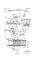
- Fig. 1 is a diagrammatic illustration of a combined condensing steam power plant and an air turbine power plant constructed and arranged in accordance with my invention
- Fig. 2 illustrates diagrammatically a modification of the system shown in Fig. l with respect to compressor intercoolers and the regulating apparatus for the same;
- FIG. 3 illustrates diagrammatically a modified arrangement of a portion of the apparatus shown in Fig. 2;
- Fig. 4 shows graphs of thermal performance of the combined plant and a basic steam plant
- Fig. 5 is a sectional elevation of a heat absorbing unit constructed in accordance with my invention.
- Fig. 6 is a sectional view taken on the line B6 of Fig. 5;
- Fig. 6A is a fragmentary section taken on the line 6A6A of Fig. 5.
- Figs. '7 and 7A are sectional views taken on the lines l'
- Fig. 8 is a diagrammatic illustration of the arrangement of control apparatus
- Fig. 9 illustrates diagrammatically a modified arrangement of air turbine drive for the compressor set and the power generator
- Fig. 10 illustrates a modified arrangement involving a non-condensing steam turbine drive for the compressor set
- Fig. 11 illustrates a modified arrangement involving a condensing steam turbine drive for the compressor set
- Fig. 12 illustrates in diagrammatic manner an arrangement for automatic control involving variable speed operation of the compressor set
- Fig. 13 illustrates a modification in which the compressor set is driven jointly by a non-condensing steam turbine and an air turbine;
- Fig. 14 illustrates in a diagrammatic manner the adaptation of the invention to a combination of a condensing steam power plant and a fuel fired gas turbine plant.
- a binary fluid power plant is made up in general of apparatus forming an aerodynamic turbine section and a condensing vapor turbine section, interconnected and interregulated, and having a common fuel fired heat absorbing unit incorporating vapor generating and superheating surface and air heating surface and arranged to supply high temperature air and high temperature superheated vapor to the respective turbine sections.
- the fuel fired heat absorbing unit has a furnace I fired with one or more pulverized coal burners 2 directed to bring together an air-borne stream of pulverized coal, conveyed by conduit 3 from a pulverizer 4 and secondary combustion air under superatmospheric pressure from a conduit 5.
- the furnace walls are lined in a well known manner with heat absorbing tubes 28 permitting furnace operation at high rates and high combustion temperatures. From the furnace the products of combustion pass across a high temperature steam superheater 6 and then pass through three parallel gas passes in which a secondary superheater 1, an economizer 8, and a high temperature air heater 9 are positioned in heat transfer relation to the gases.
- the passes are defined by partition walls l0 and H and the gas flow through the individual passes is controlled by sets of dampers l3, l4 and I5.
- a chamber 16 is provided for equalization of gas flow pressure and temperature conditions. From the chamber 16 the gases under pressure pass over a low temperature air heater tube bank I1 and then over a separate primary air heater tube bank [8 to a stack connection I9 exhausting to the atmosphere.
- a primary air blower 20 supplies air under pressure to the air heater [8 from which it fiows to the pulverizer 4 by conduit 2
- a valved bypass connection 22 is provided for purposes of regulating the temperature of the air flowing through conduit 2
- the vmanner .in which tubes- 23 are connected to Ethe stream. and wa'ter druin corresponds ate the connections rof tubesm ZB' and 4 28am: drum-#42 1 of Fig; 5; as?
- :theeonnections 45 r to -49 supply heating steam to feedwater;heaterss5l-,i.52, 153,;'-5f4and:55, respectively.
- Condensate which 3001180135 in the hot well, 56 of the condenser is withdrawn by i a vcondensate pump Bland :discharged in .heat transfer i-rela- :tionship' serially through the cooler of anzair eiec- -torinter+cooler 5:8, an oil coolers59,.a generator hydrogen coolersfilil, and a second, inter-cooler.-6.-l from which itispassed through one *ormorerheat exchangers .123 to a third after-cooler Mal-and then to the open stagefeed water heateri55.
- Condensate is Withdrawn from ,heater'55 .by condensate pump 63rand discharged into heater i5' ilfrom which the boiler-feed pump 64 discharges the condensate'zth'r'ough' the .higher pressures-stage heaters 53,152 and 5.! .in series, with aprogressiv'e heating of the 'water :to :the :extent 'thatwat full rate output of "the turbine the temperature of the water leaving heater #5! willznotqbe greatly below the boiler water. temperature, so :thatonly-a relatively small economize! will be required .to heat the water "to that temperature.
- an :gadvantag-eous recovery is smade roof :substantially all A of the inter-cooler :heat zwhich sis usuallyof :the order of 30%dof the-heat input into vages turbine-or aerodyna ic -plantvcyc1e, .while i at ithereame timethe. .efiiciency, of the compressor is i-improyedpyer what it ,WQuld hewithof :the compressor through. conduit to atheslow itemperaturer-airheater v1 iisz maintained at adaem- ;penature-.suflioiently belowethe temperature 10f: the
- boiler feed water condensate for compressor inter-stage air cooling thus contributes to the attainment of high heat absorption efficiency of the fuel fired steam generator and high pressure air heater along with improved overall thermal efiiciency of the power plant.
- the compressor being the source of pressure combustion air for the furnace, must be placed in operation before there is any heating of the air to be supplied to motivate the air turbine.
- a starting motor 98 served by electrical connections 99, is provided to turn over the compressor and the connected air turbine until such time as the air from air heater 9 is of sufficient pressure and temperature to produce the required driving power by the air turbine.
- valves 85, 88, 91 and 96 are provided to permit operation at low pressure without inter-cooling.
- the valved bypass I03 around the air turbine may be opened to pass air directly from the outlet of heater 9 to the furnace without passing through the air turbine.
- the dampers l5 are desirably restricted so that the heating of the air may be controlled until such time as the combustion conditions in the furnace are stabilized and there is sufficient flow of heating gases over and above the amount required for steam generation and super-heating to preheat the air to an operating temperature.
- the air-feed water heater 24 is provided to reduce the temperature of air exhausted from the air turbine 80 through conduit 8
- the heater 24 may be bypassed through the use of a valved bypass connection 5' between conduits 8i and 5, when the temperature of the exhaust air from the turbine 80 is suitable for the desired combustion conditions.
- Fig. 2 Binary fluid power plant with inter-cooler regulation
- Fig. 2 is illustrated a modified binary fluid power plant of the type indicated in Fig. 1 with a construction of the heat exchangers used for inter-stage cooling of the air being compressed .permitting an eifective regulation of the interstage cooling effect over a wide range of plant operation.
- the condensate is directed through the aftercooler 62 to open feed water heater 55.
- a second inter-cooler H is arranged in parallel with respect to condensate flow.
- Conduit 85 connects the discharge of the low pressure compressor 83 to the inlet of inter-cooler IE1 and conduit 87 connects the air outlet of the intercooler 16 to the inlet of the intermediate compressor S2.
- Conduit 86' connects the air discharge of compressor 82 to the inlet of the second inter-cooler H and conduit 81 connects the air outlet of the inter-cooler H to the inlet of the high pressure compressor 12!].
- Inter-cooler H is also constructed with both condensate and service water cooled surfaces 12 and i3 respectively corresponding to inter-cooler I6. Outlet connection 15 directs condensate from surface S2 to the open feed water heater 55.
- the automatic thermostatically controlled valves 15 and 16' are provided in the service water supply lines to exchanger surfaces 13 and 13' and the operation of these valves is effected by a determination of temperature in the air outlet conduits 8'7 and 81' of the inter-coolers by temperature responsive devices 11 and H respectively.
- the temperature responsive devices T! and E1 consist of gas-filled bulbs inserted through the walls of conduits 81 and B1 and connected by capillary tubes to the expansible diaphragm chamber of the valve operating mechanism for valves 16 and 16' respectively.
- conduit l-Ml' "at pressure of approximately 80 p; ssi. a. and:a; temperatureof approximately 1-33-5-Fz i
- siirefairsheater-and "aerodynamic turbine at a- V substantially constantpredetermined maximum airffiow'and capacity, but when the quantity of air" is in excessover what, may be advantaeater utihzedvfor combustion purposes in the furnace I "a portion will "be bypassed.- as above Outlined.
- the amount bypassed may be determinedby; the predetermined quantity of air needed; in furnace I to burn fuel sufficient to liberate'the heat necessary to generate and un h tvs am'ieri er am enew Pr heat. the airieaving the high pressure compressor" stage to the desired turbine inlet temperature and 1 the primary combustion air.
- the dampers l3 and i5 which areadjustablein ac-. cordance with superheatedsteam outlet temperature, are provided.
- the furnace fluid heating tubes may be used for heating either water steam or air or a combination ofsuch types of; cooling. If the'furnace is primarily of steam generating water cooled construction the;Steamgeneratmn' may; bein excess of the steam requirements of the steam prime mover on the lower fractional loads on the combined plantwhen the reduction is taken by reducing the load on the steam turbo-generator while maintaining the maximum rated load on the air. turbine. Atsuchreducedload the furnace temperature may not drop asmuch as in th'e u a eam bjoi iac .as efimtn of the air turbine requires, considerable generation of heat in the furnace.
- an additional expansion stage is provided in the air turbine 80', so that the exhaust air passing to the furnace l is withdrawn from the turbine at a point between the last two turbine stages, while the exhaust air bypassed to zone Z is taken from the discharge of the last stage through conduit I08 and valve H4 at a lower pressure and a lower temperature than the air going to the furnace.
- the compressor and air turbine handle the same amount of air at fractional loads of the combined plant and in an amount corresponding to the secondary combustion air requirement when the combined plant is at full rated load, the H power gain effected by further expansion of the air which is bypassed to zone Z is substantial.
- valves i? and I are provided, either or both being connected in operating relation with the control apparatus.
- the combined steam turbogenerator and aerodynamic turbine plant has been disclosed as adapted for modification of a regenerative steam cycle plant having a 100,000
- the aerodynamic turbo-generator would have a maximum rated generator capacity of the order of 12,000 kw. with air introduced to the air turbine at 80 p. s. i. absolute and a temperature of 1335 F., xhausting at a pressure of 16 p. s. i. absolute and with an exhaust air temperature of about 775 F. to the conduit connection to the furnace.
- the quantity of air passed through the air turbine cycle is maintained substantially constant and approximately 80% of the total combustion air requirements for fuel burning with 20% excess air, the remaining 20% being provided by the primary air blower.
- the curves shown in Fig. 4 give the calculated thermal performance of a combined plant constructed in accordance with my invention as compared to the basic steam turbo-electric plant, and illustrate factors related to the apparatus and its method of operation.
- the base coordinates are values of combined or total steam and air turbine generator outputs, while the thermal emciency values are indicated to the right of the curves A, B, and C to which they apply, while the percentage ratio of air turbine generator output to total plant generation are given by the values to the left of the curve D to which they apply.
- Curve A shows the thermal efficiency-rating relationship of the basic regenerative steam turbine plant over a rating range from 40 to 100% of its rated load, based for purpose of comparison on a constant boiler and furnace efficiency with a stack gas temperature of 321 F. This curve illustrates the variation of efficiency at fractional load. This curve is based on the steam plant having a low pressure stage condensate heater connected to bleed connection in place of inter-coolers 10 and H.
- Curve B shows the thermal efficiency-rating relationship of a combined steam and aerodynamic turbine plant with the entire inter-cooler heat taken out of the system by service water, the load range being extended beyond that of the basic steam plant due to the additional power generation by the air turbine. This is based on a constant boiler and air heater efficiency with a stack gas temperature of 405 F.
- Curve C shows the thermal efficiency-rating relationship of a combined steam and aerodynamic turbine plant with constant boiler and air heater efiiciency conditions based on a stack gas temperature of 405 F. and with the entire intercooler heat absorbed by condensate of the steam plant cycle for a range of load from the maximum down to load X and at lower loads with the inter-cooler heat absorbed partly by condensate and partly by service water, the proportion of the latter increasing with decreasing plant load.
- thermostatically controlled valves 16 and i6 regulating the introduction of service water cooling to inter-cooler heat exchange surfaces are arranged to become effective at and below load X, and due to the increasing quantity of service water inter-cooling used at lower loads the combined efficiency will be materially reduced and the curve C tends to converge with curve B and also with respect to the efliciency curve A of thesteam plant.
- Curve D illustrates the proportion of the total combined plant power output attributable to the air turbine set. It will be noted that with the operation of the air turbine at constant rating, while the load on the steam prime mover is decreased, the air turbine set will be producing 20% of the power at combined loads of of maximum load of the steam prime mover. The more efilcient air turbine set is thus utilized to its full extent and although the combined efliciency drops with loads below X, when service water inter-cooling becomes necessary, the higher proportion of the load carried by the air turbine at fractional loads is an effective factor in giving a wider load range of improved thermal economy.
- T6 efiect a further regulation in-superheat and the quantity of steam generated as may be requirjd; the construction er the heat absorbing unit shown 3 pijovides-fr a divis'ionof the: gas new irom'; the furnace into two streams one stream passing acrossa primary Superheajter section whichfi s" arranged inflsries gasnow with the high temperature outlet section 9- of the: air'hater, while the other stream passes over a secondary section; I of superheating sur face; and a s eam generating boilersctio'n 28', with bot-h streairis passing over an economizer section: arrangeclahead of an intermediate alir hater sect-10a H, The; s'team'generating section 28, shown: diagrammatically in Fig.
- thermostatically controiied' steam attemperator of the sp r'aytyp'e may be mats du'cedinto the flow path of the; primary super heater to give the desired further'regulatioit of; steam delivery temperature.
- the secondary combustion air is supplied: by one: or more condu'itsi 405 is" not only under superatrnos ph'eric pressure but at a-teniperature sub'stan hairy higher thanatmosphere;
- The'furnac is foned with gas tight fluid cooled walls and a fluid cooled floor adapted to collect and retain a shallow pool of molten ash originating from the fuel and discharging through slag outlet 4am.
- the fluid wall cooling tubes 428 in the present instance are water tubes arranged with water supply connections from and discharge connections to the elevated steam and water drum 42! of the boiler. Fluid cooling tubes conveying air or steam may be used in place of some of the water tubes or in combination therewith where radiant heating or" the air or steam is desired.
- the furnace extends upwardly, being bounded by wall tubes and a screen of tubes 428a across the lateral gas outlet 450 extending between the junction header 4GB and the lower portion of the drum.
- the rearwardly extending upright partition l formed in part of water tubes, divides the horizontally extending convection heating pass into gas passes 452 and 453.
- a gas turning space 454 extending transversely of the unit is provided and a downwardly extending gas pass 455' with additional convection heated elements is arranged to receive heating gases from the horizontal gas flow passes.
- the walls defining the outer sides of the horizontal gas passes 452 and 453 and the walls of the turning space 454 are made of a gas tight construction adapted to maintain a slightly super-atmospheric pressure Within the passes and the space, and they may be advantageously constructed to include water or other fluid heating tubes.
- the walls of the down how pass are also constructed to retain a pressure above atmosphere but as the gas temperatures will be lower, fluid heating tubes may be used primarily as structural support elements.
- a gas-tight refractory walled hopper bottom chamber Q is arranged as a gas turning space, a gas and air mixing chamber and an ash separating and collecting space.
- a final upflow gas pass is partly formed by a plurality of transversely spaced circular gas outlet passages 4S3 opening to the upper rear end of the chamber 480 and each containing a tubular air heater 4H.
- a common breeching 444 joins the passages 463 to the casing of a primary air heater 448. From the top gas outlet of the primary air heater 418, the heating gases originating in the furnace are delivered through a connector M9 to a stack discharging to atmosphere.
- feed water economizer 408a When a feed water economizer is used to heat the boiler feed water from the temperature at which it is discharged from the regenerative heating system of the steam turbine to or approaching the saturated steam temperature in the drum, such a feed water economizer 408a may be arranged in the downflow gas pass 455, with the lower inlet header 464 receiving the feed Water.
- the economizer consists of a plurality of laterally positioned multiple loop tubular elements extending across the gas pass and connected at their upper ends to outlet header 465 which is in turn connected to the water space of the steam and water drum with the customary flow regulating devices.
- Water supply connections from the water space of drum 421 are provided to the lower headers for the wall tubes 428.
- transverse junction header 466 and headers 46'! and 468 the convection heated steam generating tube bank located in gas pass 453 receives a supply of water 16 to the lower end of its L-shaped tubes 428', as shown in Fig. '7.
- the upper ends of the furnace wall and gas pass wall tubes are connected directly or through suitable junction headers to deliver steam and water to the drum 421.
- the steam which is separated from the water in drum 42! passes throughconnectors 410 to an inlet header 4H of the secondary superheater 40! consisting of a plurality of multiple loop elements pendantly positioned in gas pass 453 and the steam passing through the elements is collected by transverse outlet header 412.
- a connecting pipe 413 joins the outlet header of the secondary superheater with the inlet header 414 of the primary superheater 406 in gas pass 452.
- superheater 467 is the regulating superheater while superheater 406 having a much greater amount of heat absorbing surface does the major portion of the superheating of the steam delivered by the drum.
- a pipe 29 conveys superheated steam to the steam consumers, of which the steam turbine 41 of the combined plant utilizes the major portion.
- an attemperator may be introduced intermediate the length of the flow paths of the multiple loop tubular elements which form the heat absorbing surface of the primary superheater.
- heat transfer surface consisting of tubular elements is so arranged that a minimum pressure drop will occur in the passage of the air from the inlet to the low temperature heaters to the air outlet of the high temperature heater, while at the same time the air heating surfaces are so arranged that they may be economically constructed.
- the convection superheater 406 may be replaced as a whole, or in part, by radiant absorption superheating elements, as indicated by tubes 60, in Fig. 13, in which case the high temperature air heater portion 40%, which will be described hereinafter, will be brought closer to the furnace and subjected to much higher gas temperatures.
- the high pressure air heating surface is divided into low, intermediate and high temperature sections which are serially connected for air flow in counterflow relation to the heating gases.
- the low temperature inlet section is formed by the three upright straight tube heaters 4H, receiving air at their upper ends from the discharge of the last stage compressor with the air flowing about the outside of gas flow tubes and discharging at the lower end thereof to the inlet manifold of the intermediate section 4H, which is formed by a plurality of laterally spaced multiple loop tubular elements through which the air flows.
- the high temperature section 409 is in the present instance formed in two portions, the inlet portion 409a being located in the down gas pass 455 directly above the economizer 403a and the serially connected outlet portion 409?) in the horizontal gas pass 452 at a position rearward of super-heater 406.
- the high pressure air heated to the operating temperature by the high temperature section is delivered from outlet manifold 449 to the inlet of the air turbine for expansion and power generation.
Landscapes
- Engineering & Computer Science (AREA)
- Chemical & Material Sciences (AREA)
- Combustion & Propulsion (AREA)
- Mechanical Engineering (AREA)
- General Engineering & Computer Science (AREA)
- Engine Equipment That Uses Special Cycles (AREA)
Description
Sept. 29, 1953' w, HELLER 2,653,447
COMBINED CONDENSING VAPOR AND GAS TURBINE POWER PLANT Filed 001;. 31, 1946 12 Sheets-Sheet l HYDROGEN OOOLER STARTING MOTOR FLOW COMPRESSOR Fig.1
INVENTOR ewis W e/[er ATTORNEY Sept. 29, 1953 L. w. HELLER I 2,653,447
COMBINED CONDENSING VAPOR AND GAS TURBINE POWER PLANT Filed 001;. 51, 1946 12 Sheets-Sheet 2 INVENTOR law/1; Wi d/er Sept. 29, 1953 L. w. HELLER 2,653,447
COMBINED CONDENSING VAPOR AND GAS TURBINE POWER PLANT Filed Oct. 31, 1946 12 Sheets-Sheet 3 OOOO ' OOOOOOOOOO ATTEMPERATOR/ Fig.3
INVENTOR Lewis WJ/E/li TTQRNEY Sept. 29, 1953 w. HELLER 2,653,447
COMBINED CONDENSING VAPOR AND GAS TURBINE POWER PLANT Filed Oct. 51, 1946 12 Sheets-Sheet 4 3nnentor lewl's Wild/er Gttorn eg L. W. HELLER Sept. 29, 1953' COMBINED CONDENSING VAPOR AND GAS TURBINE POWER PLANT Filed Oct. 31, 1946 12 Sheets-Sheet 5 4/ I. m n 1 9 a i 2 d l fl A I. m Ul/l/l/ll/I B M 4 2 mm 4 M n lira/$1516 F; 2451! Fill/511115. s T W U 0 v 1 1 A llllrllllllllllllll VII/Ill rlllll/l/lll/l/l/l/lIII/I!llIll/11111115651111!!!III/IllI ll u,
//////////I/////////// IIIIIIIIIIIIII IIIIIIIIIII l NVE TO R l ems .aVe/ler BY ATTO RN EY FROM PIPE I08 L. W. HELLER Sept. 29, 1953 COMBINED CONDENSING VAPOR AND GAS TURBINE POWER PLANT Filed Oct. 31, 1946 12 Sheets-Sheet 6 m. w m 4 INVENTOR l e Wis Wj eller BY ATTO RN EY Sept. 29, 1953 L. w, HELLER 2,653,447
COMBINED CONDENSING VAPOR AND GAS TURBINE POWER PLANT Filed 001'. 51 1946 12 Sheets-Sheet 7 A1 /I l a SUPER- HEATED L200 sTEAM LINE FROM AIR HEATER TEMPERATURE RESPONSIVE ELEMENT O O O O O O O O O 0 28 3 0 :1 /7 8 I66 6 5 I54 3 O O O O O O O O 07 \TEMPERATuRE RESPONSIVE ELEMENT //0 80 j (f n vENToR ,[ewzs Wfle/ler ATTO R N EY Sept. 29, 1953 Filed Oct. 51, 1946 L. W. HELLER COMBINED CONDENSING VAPOR AND GAS TURBINE POWER PLANT l2 Sheets-Sheet 8 I 7 12 I JMMW WWW/73 eova 5 P43 730 235 226 F a7 a7 nu :1; 8a I INVENTOR Sept. 29, 1953 w. HELLER 2,653,447
COMBINED CONDENSING VAPOR AND GAS TURBINE POWER PLANT Filed Ot. 51, 1946 12 Sheets-Sheet 9 INVENTQR Zewzs Wf/ei/er Oil/M ATTORNEY Sept. 29, 1953 v 1.. w. HELLER 2,653,447
COMBINED CONDENSING VAPOR AND GAS TURBINE POWER PLANT Filed Oct. 51, 1946 12 Sheets-Sheet 1o 239a 239a 2395 kg /5 7 I INVENTOR f! 12 Lewis WHeY/er ATTORNEY Sept. 29, 1953 L. w. HELLER 2,653,447
' COMBINED CONDENSING VAPOR AND GAS TURBINE POWER PLANT Filed Oct. 51, 1946 l2 Sheets-Sheet ll 8a 70 26' 13 0 M n o 6 0 Al" 3,28 28 8 mm 0 O 1 2 2 V g 95L; q z 28 M I Q 7 K19! p 5. /oo
u INVENTOR Fl 13 Lewis Wa s/[er ATTORNEY Sept. 29, 1953 Filed Oct. 51, 1946 L. W. HELLER COMBINED CONDENSING VAPOR AND GAS TURBINE POWER PLANT 12 Sheets-Sheet l2 SUPERHEAT BOILERS FLUD FUEL 528 +677 50/ 5 528': 6/6
/F'EED WATER HEATER STARTING MOTOR FLUID FUEL Fig. 14
INVENTOR Lewis 71 Heller OLM ATTORNEY Patented Sept. 29, 1953 COMBINED .CONDENSING YAPOE AND (i s TURB N POWER PLA Lewis iHeller, Yardley, -Pa., assignor to The Babcock & gWilcox CompanyyNewYor-k, N. Y., a. corporation .of New Jersey Application octob er 31, 1946, Serial No. 706,926
The present invention relates to theconstruction and'operation of binary fluid power plants,
and more particularly, to improvements :in the construction and operation of large capacity power plants of this general type for increasing the overall thermal eificiency of the plant.
EEhe .present :invention has for its primary 'ob- J'ect the provision ofa binary fluid power plant system :which may be economically constructed tooperate with ,highpower output capacities and high thermal ,efliciency.
A further object of "the invention is the ,pro- @vision-of a binary l'fiuid power plant of :the char- :acter described which utilizes readily available and .;correspondingly cheap motive fluids.
Another object of :the invention is the provi-- .sion of a power plant :in which a gaseous fluid prime mover may 'be advantageously utilized ,in production :01 power from .a heated gaseous fluid :deriving its :heat from the burning .of :iuel but without contaminationbythe products of .com- :bustion of the v:fuel.
Another object is .the provision .of a binary afluid power :plant which combines .;a vapor prime .mover section :and a pressuregaseous fluid sec- :tion having {a multi-stage compressor for :the gaseous fluid .wherein, compressor .interstagepQQl- :ing :of :thegaseous fluid is attained ;by transfer :of heat :to :the reed ,--liquid of the vapor section yapor generator.
Anothenobject is the provision of a :binaryfluid ipower:plant whichpcombinestarvaporprimezmover section and a pressure gaseous fiuidsectionand in'awhich-zthezexhaust {from a gaseous ;fluid :.prime :mover .is directed :into heat {transfer relationship iwi the :heat zabsorbi-ng surface :of :fuel ,fired .vaporieenerator, whereby a portion of the heat ;of-the;exhaust may :be more-effectively utilized.
Another ;ob,iect is the provision .of .a :binary fluid ppmergplant :which combines a vapor gen- ,erator and :a pressure'egaseous fluid primeimover which :exhausts azheated combustion ;constituent ;to athe fuel fired iu-rnace :of the, vapor generator, .with apparatus :for attaining poordinated reguilation .;of .the variable operating .;factors .of :the apparatus.
=Anothen-objectzisthezprovisionpf a binary-fluid .primeAmOVer type power plantcomp tising a vhigh itemperature :low apressuremot .gase prime .mover Mhichdeliversdts exhaust heat into. a .vapor gencrating and. vapor heating .unit which in turn de iver .asu erh ated :vap to a vapor prim mover, {the recovery of gthe inter-cooler heat of the gas prime mover compressor into the feed wat qrc e of .theraporis ner ting andrheating unit.
-26 Glaims. (CI. 60-49) ,Another object is the provision .of a .binary efluid power plant consisting of a .variablespeed air compressor supplying air in accordance with trequirementsiof combustionof a fuel :fired furnace which serves a vapor generator and "superheater and .an air .preheater, with the preheated pressure air being expanded through a prime mover to generate power.
'Anotherobjectis the provision. of a binary .fiuid power plant cycle involving the -multiple..stage compression of air, inwhich theheat removediby inter-coolersbetween stages of theair compressor supplying air under pressure to an aerodynamic turbine and to afurnace, isrecovered forutilization in the vapor section heat .cycle with control apparatus regulating related .elements in .a manner to attain a high efficiency over a wide load range.
Another object is to simplify .a power -.plant cycle through the use of Va super-atmospheric furnace serving .a vapor generating and .superheating unit .and air heater, by supplying .com-
bustion air te the .furnace direct from :the exhaust of an aerodynamic turbine at a super-at- :mosphericrpressuresufficient to overcome thefiow resistance imposed .by the heat absorbing ele- ;ments of the :vapor generating and .superheating unit and air heater.
Anotherobject is'theprovision of a binaryfiuid .powerplanticomprising a combination of a-condensing vapor power generating system and a heated gaseous fluid .power generating system with efiective inter-connection of the .two .systems through heat exchange between the low temperature fluids being fedzto their respective heaters, aswell as-bya-utilization of heat the gaseous exhaust from the gaseous fluid prime .mover .in the generation ,of vapor and .the heating of the gaseous ,fluid.
Another object is the provision of apparatus for and a method .of operation of a binary fluid power l n whe a var at in t excess air introduced to the furnace along with combustion air for the fuel is utilized in affecting -furnace and-gas temperature forthe purpose of varying heat absorption to radiant and convection heat absorbing surfaces served thereby.
Another object is to incorporate a gaseous fluid prime mover into a combination binary :fluid .power .plantinamanner to permit .the plant to respond quickly to .rapid changes in connected load.
Another object is the provision ;of combustion control apparatus regulating fuel and combusa 'ri fli 1 2 inmat aW Qh SllPlfliiS h atin gases at varying rates of flow for the generation of 3 large quantities of steam and for the high temperature heating of corresponding large quantities of air with a varying ratio of steam to air quantities.
Another object is the provision of a gas turbine in combination with a vapor generating and utilizing power plant in such a manner to secure a higher thermal operating efficiency for the combination than that of the basic steam plant.
Another object is the provision of a high capacity power plant involving the utilization of a high temperature non-condensing gaseous fluid prime mover and developing its heat supply by the burning of ash-carrying pulverized fuel at high rates and at high furnace temperatures within the ash fusion temperature range.
Another object is the provision of a fuel fired superheated steam generator and air heating unit in which steam superheating and high temperature air heating are accomplished by products of combustion fiowing from a common furnace, while low temperature air heating is accomplished by heat transfer from a combination of the products of combustion and super-atmospheric temperature air exhausted from a multiple stage aerodynamic turbine served by the air heating unit.
Another object is the provision of a multiple stage aerodynamic power generating prime mover and conduit connections from two or more stages thereof whereby air at different pressures and temperatures may be advantageously exhausted for use as combustion air in a related air heating furnace or exhausted in part to the heating gas pass rearwardly of the furnace in respect to gas flow.
Another object is the provision of a fuel fired heat absorbing unit arranged to simultaneously generate and superheat large quantities of steam and heat correspondingly large quantities of air under a substantial super-atmospheric pressure, with an air delivery temperature of 1300 F. or above.
The various features of novelty which characterize my invention are pointed out with particularity in the claims annexed to and forming a part of this specification. For a better understanding of the invention, its operating advantages and specific objects attained by its use, reference should be had to the accompanying drawings and descriptive matter in which I have illustrated and described preferred embodiments of my invention.
Of the drawings:
Fig. 1 is a diagrammatic illustration of a combined condensing steam power plant and an air turbine power plant constructed and arranged in accordance with my invention;
Fig. 2 illustrates diagrammatically a modification of the system shown in Fig. l with respect to compressor intercoolers and the regulating apparatus for the same;
Fig. 3 illustrates diagrammatically a modified arrangement of a portion of the apparatus shown in Fig. 2;
Fig. 4 shows graphs of thermal performance of the combined plant and a basic steam plant;
Fig. 5 is a sectional elevation of a heat absorbing unit constructed in accordance with my invention;
Fig. 6 is a sectional view taken on the line B6 of Fig. 5;
Fig. 6A is a fragmentary section taken on the line 6A6A of Fig. 5.
Figs. '7 and 7A are sectional views taken on the lines l'| and lA-lA respectively of Fig. 6;
Fig. 8 is a diagrammatic illustration of the arrangement of control apparatus;
Fig. 9 illustrates diagrammatically a modified arrangement of air turbine drive for the compressor set and the power generator;
Fig. 10 illustrates a modified arrangement involving a non-condensing steam turbine drive for the compressor set;
Fig. 11 illustrates a modified arrangement involving a condensing steam turbine drive for the compressor set;
Fig. 12 illustrates in diagrammatic manner an arrangement for automatic control involving variable speed operation of the compressor set;
Fig. 13 illustrates a modification in which the compressor set is driven jointly by a non-condensing steam turbine and an air turbine; and
Fig. 14 illustrates in a diagrammatic manner the adaptation of the invention to a combination of a condensing steam power plant and a fuel fired gas turbine plant.
The binary fluid power plant In accordance with my invention, a binary fluid power plant is made up in general of apparatus forming an aerodynamic turbine section and a condensing vapor turbine section, interconnected and interregulated, and having a common fuel fired heat absorbing unit incorporating vapor generating and superheating surface and air heating surface and arranged to supply high temperature air and high temperature superheated vapor to the respective turbine sections.
In the embodiment illustrated in Fig. 1, the fuel fired heat absorbing unit has a furnace I fired with one or more pulverized coal burners 2 directed to bring together an air-borne stream of pulverized coal, conveyed by conduit 3 from a pulverizer 4 and secondary combustion air under superatmospheric pressure from a conduit 5. The furnace walls are lined in a well known manner with heat absorbing tubes 28 permitting furnace operation at high rates and high combustion temperatures. From the furnace the products of combustion pass across a high temperature steam superheater 6 and then pass through three parallel gas passes in which a secondary superheater 1, an economizer 8, and a high temperature air heater 9 are positioned in heat transfer relation to the gases.
The passes are defined by partition walls l0 and H and the gas flow through the individual passes is controlled by sets of dampers l3, l4 and I5. Rearward of the outlet of the passes a chamber 16 is provided for equalization of gas flow pressure and temperature conditions. From the chamber 16 the gases under pressure pass over a low temperature air heater tube bank I1 and then over a separate primary air heater tube bank [8 to a stack connection I9 exhausting to the atmosphere. A primary air blower 20 supplies air under pressure to the air heater [8 from which it fiows to the pulverizer 4 by conduit 2| at a pressure sufiiciently above atmosphere to overcome the pulverizer pressure drop and provide a superatmospheric pressure for the fuel and air discharged through the burners 2. For purposes of regulating the temperature of the air flowing through conduit 2|, as required by the fuel and pulverizer characteristics, a valved bypass connection 22 is provided.
A conduit 23 supplies feedwater from a feedwater supply reservoir and condensate heated by turbine stage bieed neaters -as wi1libe:-1aterrde'- scribed, to an air feedwater heater 24 frommhich "it fiow's througlr' feed 'pipe zli tolthe m ultiple'zloop -eco'n'oin'izei' "8 and' 'th'en' to a beiler' steam" and water drum-=21 by a feed connection .26. The water sp'acef of the steam and water =drum' i 21 is connected in a circulatory arangem'ent to steam eneratingtubes, some 0f whicm -such:-as the tubesia, extend along the' walls :of the furnace icnamber ann:acioss the ga's out1et -to the pri- "Ifiady'" superheater section :6; The vmanner .in which tubes- 23 are connected to Ethe stream. and wa'ter druin corresponds ate the connections rof tubesm ZB' and 4 28am: drum-#42 1 of Fig; 5; as? hereiiiait'e described.- Thevisteam' generated in the tiibes- --1S' separated from" the water in ithe drum and passed serially1through the isuperheateri sectioiis I 5 and fi'ifo'r superheatingmo :the :desiredideree: superheated steamvis'passed-zby piperifl "to" the throttle-valve AH-10f asteamaturbine :41
Thesteam prime mover and related vfeed water "heating auxiliaries irepresentedin Fig.1 correspend to' similar apparatus theregenerative steam plant cycle describedrby Gibson-and-Cushing in aipaper entitled"fAd vanced'Design in New 160,000 kwL-Oswego' Steam station as published 'intheTransactions-"of the American Society of Mechanical Engineers of August= 1942', pp. 541- 554: The steam pressure; temperature and rate of :flow of I thesteam *turb'ine, as well asthe reed Water and condensate temperatures involved,are
disclosed by the :heat-balancediagram of Fig. 6
' appearing on page 545 ofeth'e publication and; the
datasubmitted therein illustrates important OhfilfiOtGIiStiCSOflthB steam plant includedyinthe presentt combination.
Asindicated in Fig. 1, :theeonnections 45 r to -49 supply heating steam to feedwater;heaterss5l-,i.52, 153,;'-5f4and:55, respectively.
Condensate which 3001180135 in the hot well, 56 of the condenser is withdrawn by i a vcondensate pump Bland :discharged in .heat transfer i-rela- :tionship' serially through the cooler of anzair eiec- -torinter+cooler 5:8, an oil coolers59,.a generator hydrogen coolersfilil, and a second, inter-cooler.-6.-l from which itispassed through one *ormorerheat exchangers .123 to a third after-cooler Mal-and then to the open stagefeed water heateri55.
Condensate is Withdrawn from ,heater'55 .by condensate pump 63rand discharged into heater i5' ilfrom which the boiler-feed pump 64 discharges the condensate'zth'r'ough' the .higher pressures-stage heaters 53,152 and 5.! .in series, with aprogressiv'e heating of the 'water :to :the :extent 'thatwat full rate output of "the turbine the temperature of the water leaving heater # 5! willznotqbe greatly below the boiler water. temperature, so :thatonly-a relatively small economize! will be required .to heat the water "to that temperature.
In the customary regenerative steam plant "cycle a-feed water heater receiving low pressure steam froni a 'bleedconnection at v5a lower-pres- *peraturesecti'on ;9. .iIhe connections 1| .9
pared "withvan: arrangement involving theeuse 10f an: additional .xbleedp. connection .to ;a condensate .heater, andithe. additional :steam. flow; through the-turbine stages-subsequent" to :connection, 19 will generate -more:t ou/er. ifOI' the, same: initial osteam' input. 1
The: aerodynamic;;turbine sectiunziincludedfi n .then binary pfluid: power plant system has- -i=anzai turbineitlflzoperatingtwitirhighpressune hig temv-perature: which upon: expansion to a. sitter pressure-rand: temperature, ;yet still aboveatmgs- .pheric pressure; and temperature, is-;utiliz ed asja ,IGDmbMSfiOB. constituent: in the furnace i to it :flows through :conduitszB-I: and: 5-,..and athe in,-
=terposed heatexchanger. 24.
:The vairzused: as: asimoitive :fiuidgin the @Qrody namicyturbine B-B is; introduced into- .thesys inlet182i oflangaxi'alvfluwtypercnmpltessmzaltii .w 1
is driven by the aerodynamic turbine 80. 'lhe :air compressed in tne;first--,sta eaci'comnr aai is also raised in vtemperature; as :the of the compression WOIK'. The heat d i cecmpresfied air is then directed by aconduit 284,. Me lie 1&5, :and conduit :36- through thetheat -exchanger :10, Where the air temperature originatin the hctriell '56. :The air isthen directed :by conduitaelpvalue :88, conduit -89, and ivalve 90, to the inlet; :91 :of a second stage stair rcompressor :92 which .;i 'aise s the air temperature is reduced by heat 'vtransier to the :condensate :of lower temperaturecriginat- :ing'in the hotwellrfifi. 'FIBheair isthenadirected by conduit 18.7., v a1vei88, conduits-9, and :valve 9U,'It0 :the inlet 2:91 10f 'a second sta e air (3OmP eSSQ $92 which raises the 1 air to the desired :final :p fi fi ire with "someriseiinzairztemperature. The airflews throughrconduit 943,yalvei94,;andconduit5-;to the inlet of the high-:pressureairheater .ccm rising :thelow temperaturesection l1 and the highte with rinterposedyalve 156 l introduce:theh ghtemzperature high pressure air to the :air -,;turb ine in which it is expanded :to do useful mechanical 'work, "the turbine exhaustin through the con- ;duit [.04 and salve M5 to the conduit '81 By the use of condensate .-,interstage :air J-. QQ1- ring :in connection with the multiple sin l 1 0 pressor, an :gadvantag-eous recovery is smade roof :substantially all A of the inter-cooler :heat zwhich sis usuallyof :the order of 30%dof the-heat input into vages turbine-or aerodyna ic -plantvcyc1e, .while i at ithereame timethe. .efiiciency, of the compressor is i-improyedpyer what it ,WQuld hewithof :the compressor through. conduit to atheslow itemperaturer-airheater v1 iisz maintained at adaem- ;penature-.suflioiently belowethe temperature 10f: the
,heatinggasesiat the. airiheater that anieconemic design .zoi zair :heater, "with respect :to iextent :iQf
surface and draft loss, is permissible in attaining the desired gas temperature reduction. The use of the boiler feed water condensate for compressor inter-stage air cooling thus contributes to the attainment of high heat absorption efficiency of the fuel fired steam generator and high pressure air heater along with improved overall thermal efiiciency of the power plant.
By heating the air to a sufficiently high temperature while maintaining a substantial superatmospheric pressure, sufficient heat will be introduced into the air to provide upon expansion in the air turbine an excess of power over and above that required to drive the multiple stage air compressor, and the excess so developed is utilized to generate electrical energy by the generator H directly connected to the air turbine shaft. This excess of power delivered to the station bus bars through connections IH, when added to the power generated by the steam generator 43, will be the combined gross plant power output. Deductions are necessary in determining the net plant output, these being power for the condenser circulating pumps, condensate and boiler feed pumps, primary air fan and pulverizer. In the arrangement disclosed, where the furnace and heating gas passes are operated at a pressure sufiiciently above atmospheric pressure to overcome the draft loss, no induced draft fan is necessary.
In the arrangement disclosed by Fig. 1, the compressor being the source of pressure combustion air for the furnace, must be placed in operation before there is any heating of the air to be supplied to motivate the air turbine. A starting motor 98 served by electrical connections 99, is provided to turn over the compressor and the connected air turbine until such time as the air from air heater 9 is of sufficient pressure and temperature to produce the required driving power by the air turbine. In starting, multiple stage compression is not necessary, so valves 85, 88, 91 and 96 are provided to permit operation at low pressure without inter-cooling. At the same time the valved bypass I03 around the air turbine may be opened to pass air directly from the outlet of heater 9 to the furnace without passing through the air turbine.
During the starting period, the dampers l5 are desirably restricted so that the heating of the air may be controlled until such time as the combustion conditions in the furnace are stabilized and there is sufficient flow of heating gases over and above the amount required for steam generation and super-heating to preheat the air to an operating temperature.
The air-feed water heater 24 is provided to reduce the temperature of air exhausted from the air turbine 80 through conduit 8| by transfer of heat to the economizer feed water when the exhaust air temperature is higher than desirable for proper furnace operation. The heater 24 may be bypassed through the use of a valved bypass connection 5' between conduits 8i and 5, when the temperature of the exhaust air from the turbine 80 is suitable for the desired combustion conditions.
Binary fluid power plant with inter-cooler regulation In Fig. 2 is illustrated a modified binary fluid power plant of the type indicated in Fig. 1 with a construction of the heat exchangers used for inter-stage cooling of the air being compressed .permitting an eifective regulation of the interstage cooling effect over a wide range of plant operation.
In this arrangement three stages of air compression are provided by compressor units 83, 92 and 120, and air inter-coolers 10 and H are arranged between compressors 83 and 92 and between compressors 92 and I20. The air under super-atmospheric pressure and temperature leaving the respective compressors is cooled in the inter-coolers by either condensate or by service water or partly by each, to the desired outlet temperature. Heat is abstracted from the heated air in the coil 14 of the inter-cooler l0 first by tubular heat exchange surface 12 through which condensate from condenser 42 is forced by hotwell pump 51. The air introduced into the inter-cooler may also be cooled by auxiliary tubular heat exchange surface 13 through which service cooling water may be directed from a service pump 51a. From the outlet E5 of the condensate cooled surface 12 of inter-cooler 10,
the condensate is directed through the aftercooler 62 to open feed water heater 55.
A second inter-cooler H is arranged in parallel with respect to condensate flow. Conduit 85 connects the discharge of the low pressure compressor 83 to the inlet of inter-cooler IE1 and conduit 87 connects the air outlet of the intercooler 16 to the inlet of the intermediate compressor S2. Conduit 86' connects the air discharge of compressor 82 to the inlet of the second inter-cooler H and conduit 81 connects the air outlet of the inter-cooler H to the inlet of the high pressure compressor 12!]. Inter-cooler H is also constructed with both condensate and service water cooled surfaces 12 and i3 respectively corresponding to inter-cooler I6. Outlet connection 15 directs condensate from surface S2 to the open feed water heater 55.
By the described arrangement of inter-cooler heat exchange surfaces it is possible to cool the air introduced into each inter-cooler solely by either condensate or service water, or by both simultaneously.
In the combination power plant described it is advantageous from a thermal efiiciency standpoint to absorb as much of the inter-cooler heat into the feed water cycle as possible, and to do this as much heat as possible should be transferred by the inter-coolers Hi and ll to the condensate from pump 51. As will be hereinafter explained, under certain plant loading conditions an insufficiency of condensate to adequately cool the air flowing through the inter-coolers may occur and for such conditions the auxiliary service water cooled inter-coolers 13 and I3 are brought into action in order to reduce the temperature of the air leaving the inter-coolers iii and H to the desired temperatures at the inlets of compressors 92 and I20. To effect this modification of the inter-cooler operation, particularly under rapidly changing load conditions, the automatic thermostatically controlled valves 15 and 16' are provided in the service water supply lines to exchanger surfaces 13 and 13' and the operation of these valves is effected by a determination of temperature in the air outlet conduits 8'7 and 81' of the inter-coolers by temperature responsive devices 11 and H respectively. The temperature responsive devices T! and E1 consist of gas-filled bulbs inserted through the walls of conduits 81 and B1 and connected by capillary tubes to the expansible diaphragm chamber of the valve operating mechanism for valves 16 and 16' respectively. When, as for example due? toea reductioniin. flow. off condensate. to' surface:12=;:the air introduced throu h cone duit 8621s not' i'e'duced to the desired -pre'determined temperature at the" position of; temperatur'e; device 1'1", the: temperatureresponsive devicewill: cause valvewl' eto open toy'an extent" permittlngfithe flow of-sufiicient. water. through surface 13 to reduce the outlet: airto=the-desire d temperaturez Should the 'condensate' 'fiowl increase after-i the'valve- T5515 partly open, thentha -device- "11 "will. operate to automatically reduce therservice'waterfiow.
tWhen service water 'flowing throughf-surface' 1 3 absdrbs: heat from the air-and-the water is wasted, a heat. lossrfrom the: thermal: cycle 00-- curs andi 'th'e: use offservice water. is: therefore minimized. Theithermostatie'control of service water= inter-cooling; of "the: compressedair "is; an important factor in maintainingoptimum. thei mal *efiicien'cy operating conditions under 'Var-iable load and". condensatefifiow rates; The 10ptimum temperatures forfithe? air streams leaving;
the respective intercoolers 1-0. andrli'through conduitss'81 and 8'1. aredependent o'n "the'des-ig'n characteristics of the multiple stage compressor. plant, *a-ndthe; d'esiredair temperature to the ini-et 'of the pressureair heater l1. V
- After. leaving the inter cooler 1 l "the cooledairfundem pre'ssure'tisc introduced to the inlet of the hig'hwpressure T compressor I 21! and 'is com-'- pressedi-to at Working: pressure of the order of; 90' p=:s;. izsabsolute anda a temperature at apflproximately-{8'7 F." at whichjit' is introduced: into the low temperature: closed air heater section l-'|:-"and: heated-1' by products-10f" combustion flowin'g" fromz-the: furnace I. In the Fig..- 2;arrange ment-after?being. heated in the low temperaturesection, the air" is-z passed: throughran intermediate-"airheater section: H and: thenfithrough a highctemperature section ll from which it is dis charge'd. through conduit l-Ml': "at pressure of approximately 80 p; ssi. a. and:a; temperatureof approximately 1-33-5-Fz i The high temperature a-ir flowing in; the 7 conduiti [U0 'is thus at apressure-andtemperature suflicient to generate: power uponexpansion through the? multiple-stage-aerodynamic' turbine BULdrivirigrthe electric ggenerator H9; andythe compressors 833F532 and;l 2!li:th1' oug;h aconnecting shaft H2. As in the method ofoperation described in? connection with: Fig 1,, all: of the air may.*bezexhausteddromi-the turbine at a: pressure slightly above atmospheric to create a pressure in the furnace I suflicient to overcome thadraft lo'sssove'r themonvectiom heated surface includingfthesteam generating. tubes 28, superheater. sections 65 and 1;, and an: economizer S r-alternativelyfaportion of the air exhauste t from the-"turbine atyavtemperatureof the orderoil 70"0 tor 800 F. may' be exhausted directly througha; conduit Hi8: controlled by a valve I [3 to a: rear: ward Y position in the heating. "'g'a's pass, as; for exampiethe chamber" I 6 or'zone Z, where-the products of combustion "are at a: temperature considerably below the temperature at. which they 'leavethe combustion chamber I-.
The arrangement shown in' Fig; 2 is.- designedfor the-operatiomof the"compressor, high;-pres;-
siirefairsheater-and "aerodynamic turbine at a- V substantially constantpredetermined maximum airffiow'and capacity, but when the quantity of air" is in excessover what, may be advantaeater utihzedvfor combustion purposes in the furnace I "a portion will "be bypassed.- as above Outlined. The amountiof-j airbypassed fromsthe 10 air turbine exhaust to the rearward chamber 16 through conduit IOBis controllable by valve H3; asthe pressure in the chamber to is lower than at the finalstage exhaustof the turbine or in the furnace l. The amount bypassed may be determinedby; the predetermined quantity of air needed; in furnace I to burn fuel sufficient to liberate'the heat necessary to generate and un h tvs am'ieri er am enew Pr heat. the airieaving the high pressure compressor" stage to the desired turbine inlet temperature and 1 the primary combustion air.
ifisthe fuel red r ements are basedon superheated steam generation from waterdischarged from-the high pressure heater 5i, through 'feed water line-25 andthe heating of airto the optimum turbine inlet temperature, the combi'i stion control must take ;these two factors into considorationand either. areduction in steam pressure or a lowering of the airturbine air inlet temperature from a predetermined level should cause an increase in fuel: introduction. The division of' the air exhausted-from the turbine into two streams, one flowing through conduit 5 to the burners and furnace to be used as combustion air and the other bypassed to zone Z is controllable by valve ill? and I l 3;t o maintain the proper predetermined fuel-air ratio, W u
As av meansof regulatingthe distribution of heating gases between the steam superheating andhigh temperature air heating section, the dampers l3 and i5 which areadjustablein ac-. cordance with superheatedsteam outlet temperature, are provided.
The furnace fluid heating tubes may be used for heating either water steam or air or a combination ofsuch types of; cooling. If the'furnace is primarily of steam generating water cooled construction the;Steamgeneratmn' may; bein excess of the steam requirements of the steam prime mover on the lower fractional loads on the combined plantwhen the reduction is taken by reducing the load on the steam turbo-generator while maintaining the maximum rated load on the air. turbine. Atsuchreducedload the furnace temperature may not drop asmuch as in th'e u a eam bjoi iac .as efimtn of the air turbine requires, considerable generation of heat in the furnace. A contemplatedmethod of QQ I-ati wmmpemate o s c a Q i Q i volves a variation in the excess air introduced into the furnace as measured by the theoretical combustion air. requirements of the fuel, the lower combustion temperatures with high excess air being utilized to avoid-excess steam generation.
' Lower,furnace temperatures through operation with reference to Fig. 2.
Asxtherpressure at zone Z ofqthe fuelfire d eat absor ng unit i a nr c a l l w an I that in;the-,furnace IQ due to: the-draft loss across the convection heating surface, this pressure drop, which in the Fig. 2 arrangement is accomplished by throttling valve i I3, is utilized in Fig. 3 for doing useful work with extraction of heat from the air. As compared with the turbine 80 of Fig. 2, an additional expansion stage is provided in the air turbine 80', so that the exhaust air passing to the furnace l is withdrawn from the turbine at a point between the last two turbine stages, while the exhaust air bypassed to zone Z is taken from the discharge of the last stage through conduit I08 and valve H4 at a lower pressure and a lower temperature than the air going to the furnace. As in the designed operation of the power plant systems of Figs. 2 and 3, the compressor and air turbine handle the same amount of air at fractional loads of the combined plant and in an amount corresponding to the secondary combustion air requirement when the combined plant is at full rated load, the H power gain effected by further expansion of the air which is bypassed to zone Z is substantial.
In order to control the division of air flow between the furnace and zone Z, valves i? and I are provided, either or both being connected in operating relation with the control apparatus.
By way of example, the combined steam turbogenerator and aerodynamic turbine plant has been disclosed as adapted for modification of a regenerative steam cycle plant having a 100,000
kw. steam turbo-electric generator operable from a steam supply of 915,000 lb. per hour at 1250 p. s. 1. gauge and 900 F. at the throttle, and exhausting to a condenser vacuum of 1 inch Hg absolute. In such a combination, the aerodynamic turbo-generator would have a maximum rated generator capacity of the order of 12,000 kw. with air introduced to the air turbine at 80 p. s. i. absolute and a temperature of 1335 F., xhausting at a pressure of 16 p. s. i. absolute and with an exhaust air temperature of about 775 F. to the conduit connection to the furnace. With the arrangement shown by Figs. 2 and 3, the quantity of air passed through the air turbine cycle is maintained substantially constant and approximately 80% of the total combustion air requirements for fuel burning with 20% excess air, the remaining 20% being provided by the primary air blower.
With a rated steam turbo-generator output of 100,000 kw., the air fiow through the compressor and air turbine will be approximately 850,000 lb. per hour, and the theoretical power recovery exclusive of bearing and generator losses from the air turbine driven electric generator will be approximately 12,000 kw., giving a combined plant rated generator output of approximately 114,000 kw.
The curves shown in Fig. 4 give the calculated thermal performance of a combined plant constructed in accordance with my invention as compared to the basic steam turbo-electric plant, and illustrate factors related to the apparatus and its method of operation. The base coordinates are values of combined or total steam and air turbine generator outputs, while the thermal emciency values are indicated to the right of the curves A, B, and C to which they apply, while the percentage ratio of air turbine generator output to total plant generation are given by the values to the left of the curve D to which they apply.
Curve A shows the thermal efficiency-rating relationship of the basic regenerative steam turbine plant over a rating range from 40 to 100% of its rated load, based for purpose of comparison on a constant boiler and furnace efficiency with a stack gas temperature of 321 F. This curve illustrates the variation of efficiency at fractional load. This curve is based on the steam plant having a low pressure stage condensate heater connected to bleed connection in place of inter-coolers 10 and H.
Curve B shows the thermal efficiency-rating relationship of a combined steam and aerodynamic turbine plant with the entire inter-cooler heat taken out of the system by service water, the load range being extended beyond that of the basic steam plant due to the additional power generation by the air turbine. This is based on a constant boiler and air heater efficiency with a stack gas temperature of 405 F.
Curve C shows the thermal efficiency-rating relationship of a combined steam and aerodynamic turbine plant with constant boiler and air heater efiiciency conditions based on a stack gas temperature of 405 F. and with the entire intercooler heat absorbed by condensate of the steam plant cycle for a range of load from the maximum down to load X and at lower loads with the inter-cooler heat absorbed partly by condensate and partly by service water, the proportion of the latter increasing with decreasing plant load. The thermostatically controlled valves 16 and i6 regulating the introduction of service water cooling to inter-cooler heat exchange surfaces are arranged to become effective at and below load X, and due to the increasing quantity of service water inter-cooling used at lower loads the combined efficiency will be materially reduced and the curve C tends to converge with curve B and also with respect to the efliciency curve A of thesteam plant.
Curve D illustrates the proportion of the total combined plant power output attributable to the air turbine set. It will be noted that with the operation of the air turbine at constant rating, while the load on the steam prime mover is decreased, the air turbine set will be producing 20% of the power at combined loads of of maximum load of the steam prime mover. The more efilcient air turbine set is thus utilized to its full extent and although the combined efliciency drops with loads below X, when service water inter-cooling becomes necessary, the higher proportion of the load carried by the air turbine at fractional loads is an effective factor in giving a wider load range of improved thermal economy.
Although the plant example cited above is based on an air temperature of approximately 1335 F. entering the air turbine, a still higher air temperature as permissible by the metals available for high temperature use in the heat exchange equipment and in the air turbine will have several advantages. For example, with a temperature of the air entering the air turbine of the order of 1500 R, approximately 9% more power will be produced as compared with an inlet air temperature of 1335 F. The resulting higher air turbine exhaust temperature of approximately 900 F. will be advantageously utilized in the furnace where the adiabatic combustion temperature will be raised approximately degrees F. to increase the furnace temperature in the order of 35 degrees F. Such a higher furnace temperature results in only a negligible increase in the temperature of the gases discharged to the stack, while the higher temperature heat potential will'give a higherradiant heat absorpe titan at shatter;- rauire drve fer the eta-" A= High-temperature" gaseous fluid turbine 'eX- hausting to ammaeewiire the temperatureof are 1gasle'srisf-raised by "bl iir l iilg fuel and the prodof combustion alr utilizdfih radiantand c'diivec'tionjhattransfer for the heating or 1:x; e; 'r-f a separate expe sive regnerator type or; heat exchanger in the earnest front the turbine tp e qver neat fro'rnthe gases discharged to the Bra ree; we or genraita win this t Q' -greater rate than the rate ofha-t liberati teammate and the weight of the fired ets' of com'husti'ona'jIo accomplish the tie; sire-a r ultsainarra ngmeiit of water; steam and airl'fating' surracesindicated in- Fig.- 3 is d b a V .v .t I o Inasmuchthe weight of the products of bust ivill not d'cfase with decrease of s rapidly as the steam flow; the amount of l ne a high temperature levels for ingis greaterper unit of steam flow ower loads than at thehigher loads on the steam prime mover, and utilizationof this higher proportion will tend tomaintain a uniform de gree of sjuperheati when steam saw is decreased. T6 efiect a further regulation in-superheat and the quantity of steam generated as may be requirjd; the construction er the heat absorbing unit shown 3 pijovides-fr a divis'ionof the: gas new irom'; the furnace into two streams one stream passing acrossa primary Superheajter section whichfi s" arranged inflsries gasnow with the high temperature outlet section 9- of the: air'hater, while the other stream passes over a secondary section; I of superheating sur face; and a s eam generating boilersctio'n 28', with bot-h streairis passing over an economizer section: arrangeclahead of an intermediate alir hater sect-10a H, The; s'team'generating section 28, shown: diagrammatically in Fig. 3, is cdnnected' into the steam boiler circuit in a nianner corres'ponding to the arrangement of section 4'28 in the-heat absorbing boiler and air heater shown in Figs. 6 and '7 as hereinafter dsc'bfel'd At high steam plant loads the prodili'cts'oj combustion will divide as above providing farimum' of steam generationand super- W while withdecreased load the control d? 'pers lii will be operated to e'fiecta reduction the qifaiitit'yo'f hot gases'flowing in the second s am, wh'ereby' both the effectiveness of the s ondary' superheater 'l and the boiler section 2 will red'u'cefd. As; the gas flow over thef p imary superheater' section willbe maintained a a ling propo'rticmal rate to steam flow than? a the higher load an increased superheating eii'e'et will be attained therein whereby substan taut uniform supe heat will e attained With tenet-one or steam pan ure I: minor sec: ondary adjustment ofthedegre'" of superheat heated heat transfer "surfaces tetra:
isnecessary a thermostatically controiied' steam attemperator of the sp r'aytyp'e may be mats du'cedinto the flow path of the; primary super heater to give the desired further'regulatioit of; steam delivery temperature. suchaniattemp'er ator of the typeshownlby Rowandz etal Batent 242L761; is indicated at fifl w I Quite apart from the control oftheidistribu; tionat heat absorption to the steamgenerating; steam: superheating and airheating: surf-aces b'y means of Control of gas' fi'ow' as above outlined; a further means of effecting a variation: in'zthe propdrtion ofheat absorbed to'the'difier'ent surfaces'ma'y beaccompli'shed imthecombineda iantf by 'a variation in the'temperature of the" furnadegases aswll as their quantity through regulationo'f the excess air intro duce'd into thetfurnace with combustion air; An increase in excess air will effect a reduction infurnace temperature thereby reducing the amount of? heat absorbed v radiantly by the steam generating or fluidi heat:: ingfurnace wall surface, while at thesame: time increasing the quantity of prOdll'CtSOfI combus? tion passing. over the subsequent. convectiorr heated surfaces, so that s'uperheating and air heating by convectionwill beima'i greater ratio"? to the steam generation. Variation ini excessaairz may be readily efiected through=.the. contr1ol2oft the division of the air exhaustedbythe air tut bine into the two streamsyon'e tof th'ecfin'nacz as secondary air through conduit 5;. ands the other through conduit IOBto the rearward; zone Z of. the'air heater pass; 7 o Combined fuel firedsteam gen guitar and iiibvt temperature air heater Figs. 5, 6; 6A, 7 and 7A illustrate ,one formzofi the fuel fired heat absorbingunit depicted dia -g grammatically in Figs; 3, 10 and 11 This unitis arranged to receive a continuous supply ofife'ed water from the: regenerativeqfeed' water heating-3.-
portion'of the steam-power plant and one'- or mor e streams of .air: under super atmospheric pressure from the discharge. of, a, compressor Sfitg; and;. b5tf the burning of pulverized coal. to; generate-high; pressure superheatedsteam for the stream plant and also heat the air under a substantialsuper atmospheric" pressure toa temperature from which expansion to; approximately atmospheric pressure will produce usefulpowerin excess-of the power requirements of the compressor set. R
Inasmuch as? my combined steam air turb plant requires. heated an atom .above and advantageously utilizes highly super. ed steam; inthe steam: section;;,the heat absorbing unit is arranged so that the. optimum stearn superheatand' air temperatures may be attained; throughcthe positioning; of surfaces with respect to the heat generating furnace andby th regu lation' of heating gas flowover thetrespective surfaces; t p u 'In the construction shown by thesectional 131B. vation of Fig; 5 a pulverized fuel; burn ng fur-.- naice 4'01 is'firedl'by. a; plurality of pulverizedrfuel burnersi 40.2; spaced transversely of the furnace and eirtending: through a secondary air chain; 136K405" to. direct streamsof air-bornepulveriaed fuel. received from. one or more: pulverizers; not shown, through burner lines/24,03; between spaced furnace wall tooling tubies; 428:. The secondary combustion air is supplied: by one: or more condu'itsi 405 is" not only under superatrnos ph'eric pressure but at a-teniperature sub'stan hairy higher thanatmosphere;
-The'furnac is foned with gas tight fluid cooled walls and a fluid cooled floor adapted to collect and retain a shallow pool of molten ash originating from the fuel and discharging through slag outlet 4am. The fluid wall cooling tubes 428 in the present instance are water tubes arranged with water supply connections from and discharge connections to the elevated steam and water drum 42! of the boiler. Fluid cooling tubes conveying air or steam may be used in place of some of the water tubes or in combination therewith where radiant heating or" the air or steam is desired.
The furnace extends upwardly, being bounded by wall tubes and a screen of tubes 428a across the lateral gas outlet 450 extending between the junction header 4GB and the lower portion of the drum. From the furnace gas outlet the rearwardly extending upright partition l, formed in part of water tubes, divides the horizontally extending convection heating pass into gas passes 452 and 453. At the rear of these passes in which the convection heated tubular elements are located, a gas turning space 454 extending transversely of the unit is provided and a downwardly extending gas pass 455' with additional convection heated elements is arranged to receive heating gases from the horizontal gas flow passes. The walls defining the outer sides of the horizontal gas passes 452 and 453 and the walls of the turning space 454 are made of a gas tight construction adapted to maintain a slightly super-atmospheric pressure Within the passes and the space, and they may be advantageously constructed to include water or other fluid heating tubes. The walls of the down how pass are also constructed to retain a pressure above atmosphere but as the gas temperatures will be lower, fluid heating tubes may be used primarily as structural support elements.
Below the downflow gas pass a gas-tight refractory walled hopper bottom chamber Q is arranged as a gas turning space, a gas and air mixing chamber and an ash separating and collecting space. A final upflow gas pass is partly formed by a plurality of transversely spaced circular gas outlet passages 4S3 opening to the upper rear end of the chamber 480 and each containing a tubular air heater 4H. A common breeching 444 joins the passages 463 to the casing of a primary air heater 448. From the top gas outlet of the primary air heater 418, the heating gases originating in the furnace are delivered through a connector M9 to a stack discharging to atmosphere.
When a feed water economizer is used to heat the boiler feed water from the temperature at which it is discharged from the regenerative heating system of the steam turbine to or approaching the saturated steam temperature in the drum, such a feed water economizer 408a may be arranged in the downflow gas pass 455, with the lower inlet header 464 receiving the feed Water. The economizer consists of a plurality of laterally positioned multiple loop tubular elements extending across the gas pass and connected at their upper ends to outlet header 465 which is in turn connected to the water space of the steam and water drum with the customary flow regulating devices.
Water supply connections from the water space of drum 421 are provided to the lower headers for the wall tubes 428. Through transverse junction header 466 and headers 46'! and 468, the convection heated steam generating tube bank located in gas pass 453 receives a supply of water 16 to the lower end of its L-shaped tubes 428', as shown in Fig. '7. The upper ends of the furnace wall and gas pass wall tubes are connected directly or through suitable junction headers to deliver steam and water to the drum 421.
The steam which is separated from the water in drum 42! passes throughconnectors 410 to an inlet header 4H of the secondary superheater 40! consisting of a plurality of multiple loop elements pendantly positioned in gas pass 453 and the steam passing through the elements is collected by transverse outlet header 412. A connecting pipe 413 joins the outlet header of the secondary superheater with the inlet header 414 of the primary superheater 406 in gas pass 452. superheater 467 is the regulating superheater while superheater 406 having a much greater amount of heat absorbing surface does the major portion of the superheating of the steam delivered by the drum. From outlet header 415 a pipe 29 conveys superheated steam to the steam consumers, of which the steam turbine 41 of the combined plant utilizes the major portion. As a means of controlling steam temperature in order to prevent overheating of tubes of the superheater 406 and also for regulating superheated steam delivery temperature, an attemperator may be introduced intermediate the length of the flow paths of the multiple loop tubular elements which form the heat absorbing surface of the primary superheater.
In the heating of air for utilization in the air turbine at a substantial superatmospheric pressure and a temperature above 1200 F., heat transfer surface consisting of tubular elements is so arranged that a minimum pressure drop will occur in the passage of the air from the inlet to the low temperature heaters to the air outlet of the high temperature heater, while at the same time the air heating surfaces are so arranged that they may be economically constructed.
As an alternate construction, the convection superheater 406 may be replaced as a whole, or in part, by radiant absorption superheating elements, as indicated by tubes 60, in Fig. 13, in which case the high temperature air heater portion 40%, which will be described hereinafter, will be brought closer to the furnace and subjected to much higher gas temperatures.
As arranged in the apparatus shown by Fig. 5, the high pressure air heating surface is divided into low, intermediate and high temperature sections which are serially connected for air flow in counterflow relation to the heating gases. The low temperature inlet section is formed by the three upright straight tube heaters 4H, receiving air at their upper ends from the discharge of the last stage compressor with the air flowing about the outside of gas flow tubes and discharging at the lower end thereof to the inlet manifold of the intermediate section 4H, which is formed by a plurality of laterally spaced multiple loop tubular elements through which the air flows. The high temperature section 409 is in the present instance formed in two portions, the inlet portion 409a being located in the down gas pass 455 directly above the economizer 403a and the serially connected outlet portion 409?) in the horizontal gas pass 452 at a position rearward of super-heater 406. The high pressure air heated to the operating temperature by the high temperature section is delivered from outlet manifold 449 to the inlet of the air turbine for expansion and power generation.
Priority Applications (2)
| Application Number | Priority Date | Filing Date | Title |
|---|---|---|---|
| US706926A US2653447A (en) | 1946-10-31 | 1946-10-31 | Combined condensing vapor and gas turbine power plant |
| US381813A US2860610A (en) | 1946-10-31 | 1953-09-23 | Steam generating and superheating and air heating unit |
Applications Claiming Priority (1)
| Application Number | Priority Date | Filing Date | Title |
|---|---|---|---|
| US706926A US2653447A (en) | 1946-10-31 | 1946-10-31 | Combined condensing vapor and gas turbine power plant |
Publications (1)
| Publication Number | Publication Date |
|---|---|
| US2653447A true US2653447A (en) | 1953-09-29 |
Family
ID=24839659
Family Applications (1)
| Application Number | Title | Priority Date | Filing Date |
|---|---|---|---|
| US706926A Expired - Lifetime US2653447A (en) | 1946-10-31 | 1946-10-31 | Combined condensing vapor and gas turbine power plant |
Country Status (1)
| Country | Link |
|---|---|
| US (1) | US2653447A (en) |
Cited By (32)
| Publication number | Priority date | Publication date | Assignee | Title |
|---|---|---|---|---|
| DE1041741B (en) * | 1956-08-24 | 1958-10-23 | Licentia Gmbh | Steam generator with wind turbine system |
| US2864343A (en) * | 1953-01-27 | 1958-12-16 | Leeds And Northrop Company | Control systems |
| US2883832A (en) * | 1956-05-03 | 1959-04-28 | Samuel M Arnow | Steam power generating apparatus |
| US2886012A (en) * | 1951-10-01 | 1959-05-12 | Babcock & Wilcox Co | Vapor generators for mixed power plants |
| US2902830A (en) * | 1955-07-02 | 1959-09-08 | Lenz William | Steam power plants |
| US2907170A (en) * | 1952-12-12 | 1959-10-06 | Parsons C A & Co Ltd | Combined gas turbine and steam generator |
| US2921441A (en) * | 1953-12-17 | 1960-01-19 | Sulzer Ag | Feed water preheating system for steam power plants |
| DE1134556B (en) * | 1957-02-15 | 1962-08-09 | Siemens Ag | Gas-steam-turbine composite system |
| US3095699A (en) * | 1958-12-18 | 1963-07-02 | Babcock & Wilcox Co | Combined gas-steam turbine power plant and method of operating the same |
| DE1167122B (en) * | 1962-01-26 | 1964-04-02 | Brown Boveri Krupp Reaktor | Thermal power plant using gas-cooled nuclear reactors |
| DE1173293B (en) * | 1958-04-21 | 1964-07-02 | Rudolf Mayr Harting Dr Ing | Combined gas-steam power plant with additional firing |
| US3164958A (en) * | 1960-04-23 | 1965-01-12 | Babcock & Wilcox Ltd | Combined gas-steam turbine cycle power plant |
| US3173267A (en) * | 1963-04-10 | 1965-03-16 | Kawasaki Heavy Ind Ltd | Steam cycle in which more than two stages of feed water heating are carried out by one exhaust steam system from auxiliary turbine |
| US3974644A (en) * | 1974-08-08 | 1976-08-17 | Westinghouse Electric Corporation | Combined cycle electric power plant and heat recovery steam generator having improved multi-loop temperature control of the steam generated |
| US3978657A (en) * | 1974-02-06 | 1976-09-07 | Combustion Turbine Power, Inc. | Turbine system |
| US4028884A (en) * | 1974-12-27 | 1977-06-14 | Westinghouse Electric Corporation | Control apparatus for controlling the operation of a gas turbine inlet guide vane assembly and heat recovery steam generator for a steam turbine employed in a combined cycle electric power generating plant |
| US4479355A (en) * | 1983-02-25 | 1984-10-30 | Exxon Research & Engineering Co. | Power plant integrating coal-fired steam boiler with air turbine |
| FR2576968A1 (en) * | 1985-02-02 | 1986-08-08 | Knizia E H Klaus | METHOD AND DEVICE FOR OPERATING A POWER PLANT |
| US4896496A (en) * | 1988-07-25 | 1990-01-30 | Stone & Webster Engineering Corp. | Single pressure steam bottoming cycle for gas turbines combined cycle |
| US5212942A (en) * | 1990-11-09 | 1993-05-25 | Tiernay Turbines, Inc. | Cogeneration system with recuperated gas turbine engine |
| US5461853A (en) * | 1994-11-30 | 1995-10-31 | The Babcock & Wilcox Company | HRSG boiler design with air staging and gas reburn |
| US5558047A (en) * | 1994-11-30 | 1996-09-24 | The Babcock & Wilcox Company | Low Nox integrated boiler-burner cogeneration apparatus |
| US5575243A (en) * | 1994-11-30 | 1996-11-19 | The Babcock & Wilcox Company | Low NOx integrated boiler-burner apparatus |
| US20060144043A1 (en) * | 2004-11-29 | 2006-07-06 | Yasuhiro Takeuchi | Heat recovery equipment |
| US20070017207A1 (en) * | 2005-07-25 | 2007-01-25 | General Electric Company | Combined Cycle Power Plant |
| US20130175807A1 (en) * | 2012-01-10 | 2013-07-11 | Ichiroku HAYASHI | Electricity-generating system |
| US20160305289A1 (en) * | 2015-04-16 | 2016-10-20 | Doosan Heavy Industries & Construction Co., Ltd. | Hybrid power generation system using supercritical co2 cycle |
| US20160348540A1 (en) * | 2015-05-26 | 2016-12-01 | Alstom Technology Ltd | Lignite drying integration with a water/steam power cycle |
| TWI595203B (en) * | 2016-12-27 | 2017-08-11 | Jian Liang-Cheng | Burning furnace equipment |
| US10378763B2 (en) | 2015-12-03 | 2019-08-13 | General Electric Company | Method and apparatus to facilitate heating feedwater in a power generation system |
| US20200056511A1 (en) * | 2017-01-03 | 2020-02-20 | William M. Conlon | Cryogenic combined cycle power plant |
| US10619519B2 (en) * | 2017-12-06 | 2020-04-14 | General Electric Company | Bypass conduits for reducing thermal fatigue and stress in heat recovery steam generators of combined cycle power plant systems |
Citations (25)
| Publication number | Priority date | Publication date | Assignee | Title |
|---|---|---|---|---|
| CH86349A (en) * | 1919-09-23 | 1920-10-16 | Constam Ernst | Steam boiler system with a heat exchange device for preheating the combustion air. |
| DE526173C (en) * | 1927-02-12 | 1931-06-03 | Ver Kesselwerke A G Duesseldor | Steam generator with superheater |
| US1938366A (en) * | 1930-04-11 | 1933-12-05 | Superheater Co Ltd | Combined steam and power plant |
| US1978837A (en) * | 1933-01-18 | 1934-10-30 | Gen Electric | Gas turbine power plant |
| CH173497A (en) * | 1933-06-28 | 1934-11-30 | Bbc Brown Boveri & Cie | Steam power plant. |
| US1983624A (en) * | 1932-04-16 | 1934-12-11 | Foster Wheeler Corp | Boiler |
| GB469311A (en) * | 1936-05-06 | 1937-07-22 | British Thomson Houston Co Ltd | Improvements in and relating to gas turbine plant |
| US2110422A (en) * | 1934-09-22 | 1938-03-08 | Norguet Rene Marie Emile Omer | Boiler furnace |
| US2170350A (en) * | 1935-12-18 | 1939-08-22 | Babcock & Wilcox Co | Control system |
| US2184224A (en) * | 1937-02-17 | 1939-12-19 | Babcock & Wilcox Co | Method and apparatus for the operation of steam boilers and accessory devices |
| CH211358A (en) * | 1939-07-25 | 1940-09-15 | Sulzer Ag | Thermal power plant. |
| US2294700A (en) * | 1939-10-13 | 1942-09-01 | Gen Electric | Elastic fluid power plant |
| US2298700A (en) * | 1940-07-18 | 1942-10-13 | Bailey Meter Co | Superheater and reheat control |
| CH226747A (en) * | 1942-01-20 | 1943-04-30 | Oerlikon Maschf | Procedure for expanding an existing steam plant. |
| CH226746A (en) * | 1942-06-11 | 1943-04-30 | Oerlikon Maschf | Steam-gas thermal power plant. |
| US2340086A (en) * | 1940-10-08 | 1944-01-25 | Superheater Co Ltd | Steam generating and superheating installation |
| US2404938A (en) * | 1945-02-10 | 1946-07-30 | Comb Eng Co Inc | Gas turbine plant |
| US2428136A (en) * | 1944-04-25 | 1947-09-30 | Power Jets Res & Dev Ltd | Combustion gas and waste heat steam turbine |
| CH254066A (en) * | 1946-11-11 | 1948-04-15 | Oerlikon Maschf | Thermal power plant. |
| US2466723A (en) * | 1942-10-16 | 1949-04-12 | Ile D Etudes Thermo Mecaniques | Steam and gas power generating plant |
| US2471755A (en) * | 1944-01-05 | 1949-05-31 | Oerlikon Maschf | Steam-air-thermal power plant |
| US2486291A (en) * | 1942-03-19 | 1949-10-25 | Oerlikon Maschf | Steam-air thermal power plant |
| US2502941A (en) * | 1944-07-14 | 1950-04-04 | Bbc Brown Boveri & Cie | Arrangement for heating trains driven by gas turbine locomotives |
| US2539255A (en) * | 1941-12-23 | 1951-01-23 | Oerlikon Maschf | Steam plant for servicing power and delivering industrial steam |
| US2540598A (en) * | 1946-06-03 | 1951-02-06 | Basic Refractories Inc | Furnace equipment |
-
1946
- 1946-10-31 US US706926A patent/US2653447A/en not_active Expired - Lifetime
Patent Citations (25)
| Publication number | Priority date | Publication date | Assignee | Title |
|---|---|---|---|---|
| CH86349A (en) * | 1919-09-23 | 1920-10-16 | Constam Ernst | Steam boiler system with a heat exchange device for preheating the combustion air. |
| DE526173C (en) * | 1927-02-12 | 1931-06-03 | Ver Kesselwerke A G Duesseldor | Steam generator with superheater |
| US1938366A (en) * | 1930-04-11 | 1933-12-05 | Superheater Co Ltd | Combined steam and power plant |
| US1983624A (en) * | 1932-04-16 | 1934-12-11 | Foster Wheeler Corp | Boiler |
| US1978837A (en) * | 1933-01-18 | 1934-10-30 | Gen Electric | Gas turbine power plant |
| CH173497A (en) * | 1933-06-28 | 1934-11-30 | Bbc Brown Boveri & Cie | Steam power plant. |
| US2110422A (en) * | 1934-09-22 | 1938-03-08 | Norguet Rene Marie Emile Omer | Boiler furnace |
| US2170350A (en) * | 1935-12-18 | 1939-08-22 | Babcock & Wilcox Co | Control system |
| GB469311A (en) * | 1936-05-06 | 1937-07-22 | British Thomson Houston Co Ltd | Improvements in and relating to gas turbine plant |
| US2184224A (en) * | 1937-02-17 | 1939-12-19 | Babcock & Wilcox Co | Method and apparatus for the operation of steam boilers and accessory devices |
| CH211358A (en) * | 1939-07-25 | 1940-09-15 | Sulzer Ag | Thermal power plant. |
| US2294700A (en) * | 1939-10-13 | 1942-09-01 | Gen Electric | Elastic fluid power plant |
| US2298700A (en) * | 1940-07-18 | 1942-10-13 | Bailey Meter Co | Superheater and reheat control |
| US2340086A (en) * | 1940-10-08 | 1944-01-25 | Superheater Co Ltd | Steam generating and superheating installation |
| US2539255A (en) * | 1941-12-23 | 1951-01-23 | Oerlikon Maschf | Steam plant for servicing power and delivering industrial steam |
| CH226747A (en) * | 1942-01-20 | 1943-04-30 | Oerlikon Maschf | Procedure for expanding an existing steam plant. |
| US2486291A (en) * | 1942-03-19 | 1949-10-25 | Oerlikon Maschf | Steam-air thermal power plant |
| CH226746A (en) * | 1942-06-11 | 1943-04-30 | Oerlikon Maschf | Steam-gas thermal power plant. |
| US2466723A (en) * | 1942-10-16 | 1949-04-12 | Ile D Etudes Thermo Mecaniques | Steam and gas power generating plant |
| US2471755A (en) * | 1944-01-05 | 1949-05-31 | Oerlikon Maschf | Steam-air-thermal power plant |
| US2428136A (en) * | 1944-04-25 | 1947-09-30 | Power Jets Res & Dev Ltd | Combustion gas and waste heat steam turbine |
| US2502941A (en) * | 1944-07-14 | 1950-04-04 | Bbc Brown Boveri & Cie | Arrangement for heating trains driven by gas turbine locomotives |
| US2404938A (en) * | 1945-02-10 | 1946-07-30 | Comb Eng Co Inc | Gas turbine plant |
| US2540598A (en) * | 1946-06-03 | 1951-02-06 | Basic Refractories Inc | Furnace equipment |
| CH254066A (en) * | 1946-11-11 | 1948-04-15 | Oerlikon Maschf | Thermal power plant. |
Cited By (44)
| Publication number | Priority date | Publication date | Assignee | Title |
|---|---|---|---|---|
| US2886012A (en) * | 1951-10-01 | 1959-05-12 | Babcock & Wilcox Co | Vapor generators for mixed power plants |
| US2907170A (en) * | 1952-12-12 | 1959-10-06 | Parsons C A & Co Ltd | Combined gas turbine and steam generator |
| US2864343A (en) * | 1953-01-27 | 1958-12-16 | Leeds And Northrop Company | Control systems |
| US2921441A (en) * | 1953-12-17 | 1960-01-19 | Sulzer Ag | Feed water preheating system for steam power plants |
| US2902830A (en) * | 1955-07-02 | 1959-09-08 | Lenz William | Steam power plants |
| US2883832A (en) * | 1956-05-03 | 1959-04-28 | Samuel M Arnow | Steam power generating apparatus |
| DE1041741B (en) * | 1956-08-24 | 1958-10-23 | Licentia Gmbh | Steam generator with wind turbine system |
| DE1134556B (en) * | 1957-02-15 | 1962-08-09 | Siemens Ag | Gas-steam-turbine composite system |
| DE1173293B (en) * | 1958-04-21 | 1964-07-02 | Rudolf Mayr Harting Dr Ing | Combined gas-steam power plant with additional firing |
| US3095699A (en) * | 1958-12-18 | 1963-07-02 | Babcock & Wilcox Co | Combined gas-steam turbine power plant and method of operating the same |
| US3164958A (en) * | 1960-04-23 | 1965-01-12 | Babcock & Wilcox Ltd | Combined gas-steam turbine cycle power plant |
| DE1167122B (en) * | 1962-01-26 | 1964-04-02 | Brown Boveri Krupp Reaktor | Thermal power plant using gas-cooled nuclear reactors |
| US3173267A (en) * | 1963-04-10 | 1965-03-16 | Kawasaki Heavy Ind Ltd | Steam cycle in which more than two stages of feed water heating are carried out by one exhaust steam system from auxiliary turbine |
| US3978657A (en) * | 1974-02-06 | 1976-09-07 | Combustion Turbine Power, Inc. | Turbine system |
| US3974644A (en) * | 1974-08-08 | 1976-08-17 | Westinghouse Electric Corporation | Combined cycle electric power plant and heat recovery steam generator having improved multi-loop temperature control of the steam generated |
| US4028884A (en) * | 1974-12-27 | 1977-06-14 | Westinghouse Electric Corporation | Control apparatus for controlling the operation of a gas turbine inlet guide vane assembly and heat recovery steam generator for a steam turbine employed in a combined cycle electric power generating plant |
| US4479355A (en) * | 1983-02-25 | 1984-10-30 | Exxon Research & Engineering Co. | Power plant integrating coal-fired steam boiler with air turbine |
| EP0117667A3 (en) * | 1983-02-25 | 1985-08-14 | Exxon Research And Engineering Company | Power plant integrating coal-fired steam boiler with air turbine |
| AU573569B2 (en) * | 1983-02-25 | 1988-06-16 | Exxon Research And Engineering Company | Power plant |
| FR2576968A1 (en) * | 1985-02-02 | 1986-08-08 | Knizia E H Klaus | METHOD AND DEVICE FOR OPERATING A POWER PLANT |
| US4720968A (en) * | 1985-02-02 | 1988-01-26 | Knizia Klaus | Method and apparatus for driving an electrical power plant |
| US4896496A (en) * | 1988-07-25 | 1990-01-30 | Stone & Webster Engineering Corp. | Single pressure steam bottoming cycle for gas turbines combined cycle |
| US5212942A (en) * | 1990-11-09 | 1993-05-25 | Tiernay Turbines, Inc. | Cogeneration system with recuperated gas turbine engine |
| US5558047A (en) * | 1994-11-30 | 1996-09-24 | The Babcock & Wilcox Company | Low Nox integrated boiler-burner cogeneration apparatus |
| US5575243A (en) * | 1994-11-30 | 1996-11-19 | The Babcock & Wilcox Company | Low NOx integrated boiler-burner apparatus |
| US5461853A (en) * | 1994-11-30 | 1995-10-31 | The Babcock & Wilcox Company | HRSG boiler design with air staging and gas reburn |
| US20060144043A1 (en) * | 2004-11-29 | 2006-07-06 | Yasuhiro Takeuchi | Heat recovery equipment |
| US7581395B2 (en) * | 2004-11-29 | 2009-09-01 | Mitsubishi Heavy Industries, Ltd. | Heat recovery equipment |
| US20070017207A1 (en) * | 2005-07-25 | 2007-01-25 | General Electric Company | Combined Cycle Power Plant |
| EP1752617A3 (en) * | 2005-07-25 | 2007-05-16 | General Electric Company | Combined cycle power plant |
| US20130175807A1 (en) * | 2012-01-10 | 2013-07-11 | Ichiroku HAYASHI | Electricity-generating system |
| US8783037B2 (en) * | 2012-01-10 | 2014-07-22 | Ichiroku HAYASHI | Electricity-generating system |
| US9574493B2 (en) | 2012-01-10 | 2017-02-21 | Ichiroku HAYASHI | Electricity-generating system |
| US10072531B2 (en) * | 2015-04-16 | 2018-09-11 | Doosan Heavy Industries & Construction Co., Ltd. | Hybrid power generation system using supercritical CO2 cycle |
| US20160305289A1 (en) * | 2015-04-16 | 2016-10-20 | Doosan Heavy Industries & Construction Co., Ltd. | Hybrid power generation system using supercritical co2 cycle |
| US20160348540A1 (en) * | 2015-05-26 | 2016-12-01 | Alstom Technology Ltd | Lignite drying integration with a water/steam power cycle |
| US9835056B2 (en) * | 2015-05-26 | 2017-12-05 | General Electric Technology Gmbh | Lignite drying integration with a water/steam power cycle |
| US10378763B2 (en) | 2015-12-03 | 2019-08-13 | General Electric Company | Method and apparatus to facilitate heating feedwater in a power generation system |
| TWI595203B (en) * | 2016-12-27 | 2017-08-11 | Jian Liang-Cheng | Burning furnace equipment |
| US20200056511A1 (en) * | 2017-01-03 | 2020-02-20 | William M. Conlon | Cryogenic combined cycle power plant |
| US11053818B2 (en) * | 2017-01-03 | 2021-07-06 | William M. Conlon | Cryogenic combined cycle power plant |
| US20210355845A1 (en) * | 2017-01-03 | 2021-11-18 | William M. Conlon | Cryogenic combined cycle power plant |
| US11578623B2 (en) * | 2017-01-03 | 2023-02-14 | Pintail Power Llc | Cryogenic combined cycle power plant |
| US10619519B2 (en) * | 2017-12-06 | 2020-04-14 | General Electric Company | Bypass conduits for reducing thermal fatigue and stress in heat recovery steam generators of combined cycle power plant systems |
Similar Documents
| Publication | Publication Date | Title |
|---|---|---|
| US2653447A (en) | Combined condensing vapor and gas turbine power plant | |
| US2685279A (en) | Equalization of superheated and reheated steam temperature in steam power plants | |
| US5375410A (en) | Combined combustion and steam turbine power plant | |
| JP3032005B2 (en) | Gas / steam turbine combined facility | |
| US2471755A (en) | Steam-air-thermal power plant | |
| US2568787A (en) | Steam power plant using exhaust from auxiliary gas turbine for condensing steam | |
| US4086758A (en) | Combined steam and gas turbine plant and method of operation | |
| US3162179A (en) | Fluid circulation system for a oncethrough type steam generator | |
| US3095699A (en) | Combined gas-steam turbine power plant and method of operating the same | |
| US2184845A (en) | Pulverizing, combustion, and heat transfer plant | |
| US3304712A (en) | Steam and gas turbine power plant | |
| US3675426A (en) | Method and means for operating a steam gas plant including a gas turbine, a steam turbine with its steam generator at the downstream end | |
| US2867983A (en) | Power plant with separately fired reheater | |
| US2952975A (en) | Vapor generating and superheating unit | |
| US3032999A (en) | Steam turbine power plants | |
| US3155078A (en) | Double reheat power plant arrangement | |
| US2539255A (en) | Steam plant for servicing power and delivering industrial steam | |
| US2064444A (en) | Steam generator reheater | |
| US3186175A (en) | Heat absorption balancing system for a steam generator having a primary steam circuit and a reheating steam circuit | |
| US3055181A (en) | Method of operating a power plant system | |
| US2823650A (en) | Method and means for heat exchange between flowing media, preferably for remote heating systems | |
| US2918909A (en) | Steam generating and resuperheating plant | |
| US2106346A (en) | Power plant | |
| US2946187A (en) | Gas and steam cycle power plant having twin supercharged vapor generators | |
| US1732009A (en) | Method and apparatus for development of power |