US2650737A - Knockdown shipping container - Google Patents
Knockdown shipping container Download PDFInfo
- Publication number
- US2650737A US2650737A US135686A US13568649A US2650737A US 2650737 A US2650737 A US 2650737A US 135686 A US135686 A US 135686A US 13568649 A US13568649 A US 13568649A US 2650737 A US2650737 A US 2650737A
- Authority
- US
- United States
- Prior art keywords
- bolts
- walls
- container
- edges
- roof
- Prior art date
- Legal status (The legal status is an assumption and is not a legal conclusion. Google has not performed a legal analysis and makes no representation as to the accuracy of the status listed.)
- Expired - Lifetime
Links
Images
Classifications
-
- B—PERFORMING OPERATIONS; TRANSPORTING
- B65—CONVEYING; PACKING; STORING; HANDLING THIN OR FILAMENTARY MATERIAL
- B65D—CONTAINERS FOR STORAGE OR TRANSPORT OF ARTICLES OR MATERIALS, e.g. BAGS, BARRELS, BOTTLES, BOXES, CANS, CARTONS, CRATES, DRUMS, JARS, TANKS, HOPPERS, FORWARDING CONTAINERS; ACCESSORIES, CLOSURES, OR FITTINGS THEREFOR; PACKAGING ELEMENTS; PACKAGES
- B65D88/00—Large containers
- B65D88/52—Large containers collapsible, i.e. with walls hinged together or detachably connected
- B65D88/526—Large containers collapsible, i.e. with walls hinged together or detachably connected with detachable side walls
- B65D88/528—Large containers collapsible, i.e. with walls hinged together or detachably connected with detachable side walls all side walls detached from each other to collapse the container
Description
Sept. 1f', 1953 w. T. GEYER ETAL 2,650,737
' KNOCKDOWN SHIPPING CONTAINER -Filed Dec. 29, 1949 6 Sheets-Sheet 1 @y Mdm ATTORNEY Sept 1, 1953 v w. T. GEYER r-:rL l 2,650,737
KNocxnowN SHIPPING CONTAINEv Filed Dc. 29, 1949 'e sheets-sheet 2 Mr/m ATTORNEY 6 Sheets-Sheet C5 @HMI 4W lIHIII umm-; zo nwW- v /1 @TMA a 7 vif/ nm 1 zo 7 7 m 5w M 7 a/J- 7.0 8 m w Il l l l l l l l l l l l I l l l l l i l l l l l l I l l l l l .I W w I i/ W. T. GEYER ET AL KNOCKDOWN SHIPPING CONTAINER sept.- 1, 195s Filed Dec. 29, 1949 Sept. 1, 1953 w. T. GEYER :TAL
vKNocxnowN sHiPPING CONTAINER Filed Dec. 29, 1 949 ATTo RN EY Sept. l, 1953 w. T. GEYER ETAL 2,650,737
KNOCKDOWN SHIPPING CONTARIINER Filed Deo. 29, 1949 6 shees-sneet. 5
74a y o 15E 5 za s f i i 25 "I" 7- l 1&7 j"
. `\\\\\\\\5\\\ f I Wav/a;
ATTORNEY Sept. 1, 1953 w. T. GEYER ETAL KNOCKDOWN SHIPPING CONTAINER 6 sheets-sheet es Filed Deo. 29, 1949 Patented Sept. 1, 1953 KNOCKDOWN SHIPPING CONTAINER Wallace T. Geyer, Berwick, Reuben H. Learn, Bloomsburg, and Leonard W. Sult, Berwick, Pa., assignors to American Car and Foundry Company, New York, N. Y., a corporation of New Jersey Application December 29, 1949, Serial N0. 135,686
4 Claims.
This invention relates to shipping containers in general and in particular to shipping containers which may be knocked down to save shipping space when being moved in an empty condition.
Large quantities of materials are transported in containers having capacities approximately one-sixth that of a standard railway car. Such containers are moved by truck, rail and ship and frequently must be returned to their destination in an empty condition since it is hard to locate return pay loads. This is particularly true of shipments of diplomatic and military material shipped over seas. Frequently also in domestic service containers must be returned Without pay load and without waiting for the movement of a special container car. It is an object, therefore, of the present invention to provide a shipping container which may be readily knocked down for return shipment and which will occupy a minimum of shipping space and will not require special shipping container cars.
A further object of the invention is the provision of a shipping container which may be readily knocked down or assembled and when in the assembled condition may be handled in the same manner as present permanently assembled containers A still further object of the invention is the provision of a knock-down container in which the door will be suspended from at least three of the sides during lifting of the container.
A yet further object of the invention is the provision of a knock-down container having the parts rigidly held in assembled condition by means of sliding bolts.
These and other objects of the invention will be apparent to persons skilled in the art from a study of the following description and accompanying drawings, in which:
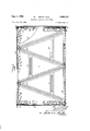
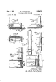
Fig. 1 is a side elevational view with portions broken away to better disclose the construction;
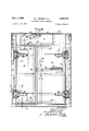
Fig. 2 is a front elevational view of the container;
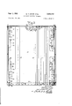
Fig. 3 is a rear elevational View also with parts vbroken away to better disclose the construction;
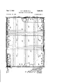
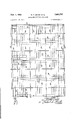
Fig. 4 is a top plan View of the container; Figs. 5, 6, '7, 8 and 9 are enlarged sectional views taken substantially on corresponding section lines of Fig. 2;
' Fig. l0 is a sectional View similar to Fig. 5 but showing the connection between a side and a rear wall;
Fig. 1l is an enlarged sectional view showing the connection between the side wall and oor,
and
Fig. 12 is a top plan view of the floor unit.
Referring now to the drawings in detail it will be seen, particularly from Fig. l, that the longitudinal side Walls are made of sheet metal plate 2, stiifened on its outer surface by means of two A-shaped braces 4 suitably spot welded or otherwise secured to the plate and additionally braced by a longitudinal tie 5. The upper ends of the A bracing members are provided with an eye in which is fastened a lifting loop 6 by means of which the container may be lifted during transport. As clearly shown, the braces are of iianged channel formation so as to give maximum rigidity with minimum weight. Along the bottom edges of each side wall is riveted or otherwise attached an offset plate 8 (Figs. 3 and 11), which oiset plate has the lower portion in direct contact with the side wall sheet 2 and the upper portion offset inwardly therefrom.
The back wall, particularly as shown in Fig. 3, is formed of metal plate I0 stiffened by anged channel stiffeners I2 extending vertically of the plate and spot welded or otherwise secured thereto. The top and side edges of the end wall plate lil are flanged inwardly as at I4 and I5 respectively. The top anges are adapted to support and be overlapped by the roof later to be described, while the side flanges I5 are adapted to overlap the side walls 2. Attached along the bottom edge of the end wall is an offset plate I6 similar in construction to the offset plates 8 attached to the side walls.
The front end wall, as best shown in Fig. 2, is formed by a top plate I8 and two vertically extending side plates 20 together defining a door opening. The plates I and 2d have their upper and side edges flanged inwardly as at 2| so as toy overlap the side walls and be overlapped by the roof in exactly the same manner as the anges It and I5 of the end Wall. Plates I8 and 2E! havel angles 22 attached thereto adjacent their inner edges, which angles stiften the plate and define the door opening. Hinges 24 are secured to plates 20 and angles 22 and carry a large door 2S and a small door 28. These doors are preferably built of fiat metal plate stiffened internally by angles 30.
" The door of the container, as best shown in Fig. 12, is formed of a top plate 32 resting upon and spot welded or otherwise secured to longitudinally and transversely extending flanged channel stiffeners 3%, all suitably connected together by welding or other securing means and attached at their outer ends to angular framing members. The framing members extending along the longitudinal sides and rear end are of deformed 2 bar shape having a bottom flange 3G, vertical web 38 and an outwardly and downwardly turned outer ange 40, which outwardly and downwardly turned flanges are adapted to overlap and interlock with. the distorted plates 8 and. lit`- of the side and end walls respectively. Thus it will be seen that during lifting the side and rear edges of the floor will be carried by and Supported along their entire length by the side and rear end Walls. of the assembled container. The front edge of' the floor frame is formed by Van angle 42 (Fig. 7.) to which is attached a flat plate 43- and stiifening angle 44, which latter will alsoserve as a protection plate during loading of the container;
The container roof, as best shown in Figs. 1 and 4, is formed of a metal. plate 46 havingthe side edges thereof turned downwardly as at 43 with the downturned edges overlapping the side and end walls of the container. The roof is internally stiffened by transversely and longitudinally extending hanged channel stiieners o suitably attached to each other and to the roof Dlate 46.
In order to secure the roof to the various side and end walls bolt keepers 52 are attached to the roof on the inner surface thereof and these keepers are preferably formed of short channel members to which are welded or otherwise secured tubular portions adapted to receive the free end. of bolts 54 slideably carried in similarly forrned bolt carriers 5t welded or otherwise secured to the side and end walls. The downturned ends 5G. of the bolts Ei/i will be held in their roof-locking position by angle retainers 62,
which retainers will also hold the bolts in their retracted position with loss of the bolts out of their carriers being prevented by small angle clips G3. Thus it will be seen that when the bolts: are in their locked position their accidental 1.
unlocking will be prevented by clips 62 and when in their unlocked position their locking or loss will be prevented by clips 62 and S3.
In each corner formed by the side walls and adjacent the upper and lower edges thereof keepers Iii of a form similar to keepers 52 are securely welded or otherwise secured to the side walls 2. Immediately above and below these keepers 1B. are spaced bolt slides 'l2 which are securely welded or otherwise secured to the rear and front wall plates lil and respectively. Slideably mounted in slides 'i2 and movable through keepers 1.0 are bolts 'i4 having a turned end 75. The right angle bend or handle portions 'LG .of the upper bolts are adapted to be held in position by the upper inclined edge of angle shaped retainers 'I8 when the bolts are in the locked position. When in the lowered or retracted position .the handles 'i6 are adapted to :fitA within a slot 19. of the angle clips to thereby retain .the bolt in its lower or retracted position, The `lower bolts 'i4 are held in their locked positionby means of the lower edgesof `angle clips 8.8, which clips are provided intermediate their ends with ,a slot 82 adapted to receive the handle portion 1G and retain the bolt in an intermediate position to assist in insertion and removal of the floor unit. When in thev fully retracted position .the handles I6 of the lower bolts areadapted to rest on .the upper. edge of retaining clips 8U with loss of the bolt being prevented .by angle members 83.
Thus it will .be seen that when the bolts 1.4 are. in .their fully locked position the side and .end walls are securely held together at a plurality of points. It will also be seen that the iloor is securely held in its position with the lips 40 in engagement with distorted plates 8 and I6 by means of the lower ends of the lower bolts 14. Upward motion of the lower bolts 14 is, as pointed out above, prevented; through' contact of handle T6 with the lower end of angle clips 86. When it is desired to remove the floor this can be done by lifting the lower bolts into slots 82 and lifting. and sliding the floor out of position.
The door 28' is securely locked in its closed position by means of upper and lower slide bolts 86 and 81' respectively, which bolts lock the door to the frame as. clearly shown in Figs. 2, '7 and 8. The door 26- is eiectively locked to the door 28 and to the door frame angles by means of slidesiiy suitably operated by a handle 90 which may be sealed against unauthorized tampering.
From the preceding it will be seen that with the container in the fully assembled condition none of the securing means can be reached by any personsv except by rst entering the container through door 26. When it is desired to dismantle the container bolts -54 will be moved to their retracted position between clips 62 and 63', after which the roof may belifted free. Following this the bolts 14 adjacent the front of the container will bev moved to their fully retracted position and the front wall with itsv attached doors removed, then the lower rear bolts 'i4 may be lifted in-to slots 82 and the floor unit removed. Following this the bolts 14 carried by the rear end walls will be moved to their full-y retracted position and the container will then be fully disassembled. In reassembling the container the reverse. operations may be followed, or the vside and rear walls may be laid fiat and the floor laid in position partially overlapping the lower edges thereof. Rotation of the sides and rear end wall to the vertical position will cause engagement. between the lips 4.0 and strips 8Iv and I6. In any event, whether the floor be placed in by thismanner or lowered into position, the `downturned lips will draw the .side andrear'end-wall into proper position for movement of the bolts i4 into their fully locked condition. It will also be obvious that seals of. either the resilient or spring metal type may be provided at all joints. It will likewise be obvious that4 various modifications ,andr rearrangementsy of parts may be. made without departing from the scope ,of the invention as defined by the following claims.
What is claimed is:
1. A knockdown container comprising, side. walls, andend wallssliding bolts located. adjacent the vertical edges of said walls and slidable ver-V tically to removably lock said walls together, a roof resting on said wa-llsqand formed with down.- turned` ilanges overlapping thewalls, sliding bolts located adjacent the .upper .edges of said walls andy horizontally slidable. to removably lock said roof and walls together, a base fitting within .the wallsadiacent the lower ,edges thereof, said 'base and walls having interengaging flanges support-I ing the base .onthe walls and preventing spreading of ythe-wa11s and being held in position by certain. of ,saidv vertically slidable bolts engaging the base to prevent upward movement thereof, and means engaging certain .of said bolts .to prevent ,vertical sliding movement thereof when in locked position.
.2. A ,knock-down .Container comprising, .side walls, end walls, -a roof and` a. base, vertically slidable bolts carried by said end Walls adjacent the vertical edges thereof, keepers carried by said side walls adjacent the vertical edges thereof and in position to be engaged by said vertically slidable bolts to removably lock said walls together, horizontally slidable bolts carried by said end and side walls adjacent the upper edges thereof, keepers carried by said roof adjacent the side edges thereof and in position to be engaged by said horizontally slidable bolts to removably lock said roof and walls together, and interengaging flanges on said walls and base whereby said base is supported on the side walls and the side walls are held against bulging, said base being retained in supported position by certain of said vertically slidable bolts acting to prevent upward movement of the base when said vertically slidable bolts are in wall locking position.
3. A knock-down container comprising, a base including' a floor plate, side Walls, end walls and a roof, means removably securing said side walls, end walls and roof together, upwardly and inwardly offset plates secured to the lower edges of certain of said side and end walls and extending above the lower edges thereof, and rolled members of Z form secured to cer-tain of the side edges of said base, said Z form members having one flange thereof outstanding and turned downwardly to interengage with Said offset plates to thereby support the base on said certain walls and prevent bulging thereof, and said one ilange being -connected to the under side of the floor plate inwardly of the edge whereby the floor plate overlaps the interengagement between the offset plates and Z form members.
4. A knock-down container comprising, side walls, end walls, a roof and a base, vertically slidable bolts carried by said end walls adjacent the vertical edges thereof, keepers carried by said side walls adjacent the vertical edges thereof and in position to be engaged 'by said vertically slidable bolts to removably lock said walls together, horizontally slidable bolts carried by said end and side walls adjacent the upper edges thereof, keepers carried by said roof adjacent the side edges thereof and in position to be engaged by said horizontally slidable bolts to removably lock said roof and walls together, and interengaging fianges on said walls and base whereby said base is supported on the side walls and the side walls are held against bulging, angle clips secured to certain of said walls to lock certain of said vertically slidable bolts in lower position, said last named bolts engaging the upper surface of said base to prevent upward movement thereof when said bolts are in locked position beneath said clips.
NALLACE T. GEYER. REUBEN H. LEARN. LEONARD W. SULT.
References Cited in the le of this patent UNITED STATES PATENTS Number Name Date 295,046 Parker et al Mar. 11, 1881 523,366 Mulford July 24, 1894 674,805 White et al May 21, 1901 765,356 Crutchfield July 19, 1904 929,684 Skiles July 27, 1909 1,017,140 Davis et al Feb. 13, 1912 1,283,890 Pritchard Nov. 5, 1918 1,322,310 Kring Nov. 18, 1919 1,414,948 Hozen May 2, 1922 1,507,557 Lohrentz Sept. 2, 1924 1,651,284 Lieberman Nov. 27, 1927 1,735,375 Card et al. Nov. 12, 1929 2,027,683 Elliott et al Jan. 14, 1936 2,141,734 Besch Dec. 27, 1938 FOREIGN PATENTS Number Country Date 303,050 Great Britain Dec. 27, 1928
Priority Applications (1)
| Application Number | Priority Date | Filing Date | Title |
|---|---|---|---|
| US135686A US2650737A (en) | 1949-12-29 | 1949-12-29 | Knockdown shipping container |
Applications Claiming Priority (1)
| Application Number | Priority Date | Filing Date | Title |
|---|---|---|---|
| US135686A US2650737A (en) | 1949-12-29 | 1949-12-29 | Knockdown shipping container |
Publications (1)
| Publication Number | Publication Date |
|---|---|
| US2650737A true US2650737A (en) | 1953-09-01 |
Family
ID=22469194
Family Applications (1)
| Application Number | Title | Priority Date | Filing Date |
|---|---|---|---|
| US135686A Expired - Lifetime US2650737A (en) | 1949-12-29 | 1949-12-29 | Knockdown shipping container |
Country Status (1)
| Country | Link |
|---|---|
| US (1) | US2650737A (en) |
Cited By (7)
| Publication number | Priority date | Publication date | Assignee | Title |
|---|---|---|---|---|
| US2839309A (en) * | 1951-06-27 | 1958-06-17 | Guy M Turner | Trussed skids for knitting machines, or the like |
| DE1057010B (en) * | 1954-08-03 | 1959-05-06 | Walter Jordan G M B H | Pressure-resistant container made of thin-walled light metal, built into a prism-shaped support frame, for transporting and storing fuel, drinking water, beverages and other liquids |
| US3040925A (en) * | 1959-01-02 | 1962-06-26 | Champion Co | General cargo shipping container |
| US3198370A (en) * | 1962-07-16 | 1965-08-03 | Gulf Ports Steamship Co Ltd | Collapsible cargo container |
| US3401814A (en) * | 1967-03-07 | 1968-09-17 | Collapsible Container Corp | Collapsible shipping container |
| US5722328A (en) * | 1995-06-06 | 1998-03-03 | T.H.E.M. International, Inc. | Pallet system including side wall latch assembly |
| US6216899B1 (en) * | 1997-12-30 | 2001-04-17 | Edda Dorothy Bragazza Vicari | Dismountable container |
Citations (15)
| Publication number | Priority date | Publication date | Assignee | Title |
|---|---|---|---|---|
| US295046A (en) * | 1884-03-11 | baker | ||
| US523366A (en) * | 1894-07-24 | Folding crate | ||
| US674805A (en) * | 1901-01-23 | 1901-05-21 | Stephen P White | Folding or knockdown crate or coop. |
| US765356A (en) * | 1903-09-08 | 1904-07-19 | Rosa Alice Crutchfield | Collapsible box. |
| US929634A (en) * | 1908-03-11 | 1909-07-27 | J F Lawler | Folding egg-case. |
| US1017140A (en) * | 1910-12-27 | 1912-02-13 | John Brooke Davis | Collapsible coop. |
| US1283890A (en) * | 1917-12-31 | 1918-11-05 | Albert R Pritchard | Convertible freight-car. |
| US1322310A (en) * | 1919-11-18 | Railroad box-car | ||
| US1414948A (en) * | 1919-11-08 | 1922-05-02 | Hazen James Alton | Collapsible metal crate |
| US1507557A (en) * | 1923-09-25 | 1924-09-02 | Edward A Lohrentz | Folding box or crate |
| US1651284A (en) * | 1926-03-06 | 1927-11-29 | Leiberman Morris | Collapsible box |
| GB303050A (en) * | 1927-09-27 | 1928-12-27 | Arthur Kitchener Walter | Improvements in collapsible boxes |
| US1735375A (en) * | 1926-02-27 | 1929-11-12 | Jamestown Metal Equipment Co I | Filing cabinet |
| US2027683A (en) * | 1934-04-03 | 1936-01-14 | Fern B Elliott | All-metal collapsible egg case |
| US2141734A (en) * | 1937-12-23 | 1938-12-27 | Harry J Watson | Casket |
-
1949
- 1949-12-29 US US135686A patent/US2650737A/en not_active Expired - Lifetime
Patent Citations (15)
| Publication number | Priority date | Publication date | Assignee | Title |
|---|---|---|---|---|
| US1322310A (en) * | 1919-11-18 | Railroad box-car | ||
| US523366A (en) * | 1894-07-24 | Folding crate | ||
| US295046A (en) * | 1884-03-11 | baker | ||
| US674805A (en) * | 1901-01-23 | 1901-05-21 | Stephen P White | Folding or knockdown crate or coop. |
| US765356A (en) * | 1903-09-08 | 1904-07-19 | Rosa Alice Crutchfield | Collapsible box. |
| US929634A (en) * | 1908-03-11 | 1909-07-27 | J F Lawler | Folding egg-case. |
| US1017140A (en) * | 1910-12-27 | 1912-02-13 | John Brooke Davis | Collapsible coop. |
| US1283890A (en) * | 1917-12-31 | 1918-11-05 | Albert R Pritchard | Convertible freight-car. |
| US1414948A (en) * | 1919-11-08 | 1922-05-02 | Hazen James Alton | Collapsible metal crate |
| US1507557A (en) * | 1923-09-25 | 1924-09-02 | Edward A Lohrentz | Folding box or crate |
| US1735375A (en) * | 1926-02-27 | 1929-11-12 | Jamestown Metal Equipment Co I | Filing cabinet |
| US1651284A (en) * | 1926-03-06 | 1927-11-29 | Leiberman Morris | Collapsible box |
| GB303050A (en) * | 1927-09-27 | 1928-12-27 | Arthur Kitchener Walter | Improvements in collapsible boxes |
| US2027683A (en) * | 1934-04-03 | 1936-01-14 | Fern B Elliott | All-metal collapsible egg case |
| US2141734A (en) * | 1937-12-23 | 1938-12-27 | Harry J Watson | Casket |
Cited By (7)
| Publication number | Priority date | Publication date | Assignee | Title |
|---|---|---|---|---|
| US2839309A (en) * | 1951-06-27 | 1958-06-17 | Guy M Turner | Trussed skids for knitting machines, or the like |
| DE1057010B (en) * | 1954-08-03 | 1959-05-06 | Walter Jordan G M B H | Pressure-resistant container made of thin-walled light metal, built into a prism-shaped support frame, for transporting and storing fuel, drinking water, beverages and other liquids |
| US3040925A (en) * | 1959-01-02 | 1962-06-26 | Champion Co | General cargo shipping container |
| US3198370A (en) * | 1962-07-16 | 1965-08-03 | Gulf Ports Steamship Co Ltd | Collapsible cargo container |
| US3401814A (en) * | 1967-03-07 | 1968-09-17 | Collapsible Container Corp | Collapsible shipping container |
| US5722328A (en) * | 1995-06-06 | 1998-03-03 | T.H.E.M. International, Inc. | Pallet system including side wall latch assembly |
| US6216899B1 (en) * | 1997-12-30 | 2001-04-17 | Edda Dorothy Bragazza Vicari | Dismountable container |
Similar Documents
| Publication | Publication Date | Title |
|---|---|---|
| US2598800A (en) | Shipping container | |
| US2869750A (en) | Container | |
| US6299008B1 (en) | Transport and storage system | |
| US2756894A (en) | Pallet with a collapsible container | |
| US4546896A (en) | Collapsible shipping container | |
| US2650737A (en) | Knockdown shipping container | |
| US3557855A (en) | Pallet having hinged end panels and flexible cover members | |
| US3382998A (en) | Cargo container with side door | |
| US3853239A (en) | Cargo container having adjustable shelves | |
| CN104554990A (en) | Loading type tray box | |
| US3101226A (en) | Knockdown metallic receptacles | |
| US3814028A (en) | Freight car with depressed center section | |
| US2299175A (en) | Collapsible box | |
| US3635368A (en) | Collapsible container | |
| US2826329A (en) | Container for use with fork lift trucks | |
| US2315094A (en) | Container | |
| US1881822A (en) | Shipping platform and collapsible tray for handling material with lift trucks | |
| US3840135A (en) | Collapsible container carrier system | |
| US3768686A (en) | Container for elongated articles | |
| US2720996A (en) | Portable packing case | |
| US20060016807A1 (en) | Foldable freight container | |
| US2932262A (en) | Reinforcing structures for temporary barricades for doors of boxcars and grain cars | |
| US2077649A (en) | Stowing facility for commodities in railway and other vehicles, and in storage warehouses | |
| US3542234A (en) | Container with walls collapsible in a stacked condition | |
| US2071620A (en) | Convertible vehicle |