US2650488A - Igniter and method of making same - Google Patents
Igniter and method of making same Download PDFInfo
- Publication number
- US2650488A US2650488A US2888A US288848A US2650488A US 2650488 A US2650488 A US 2650488A US 2888 A US2888 A US 2888A US 288848 A US288848 A US 288848A US 2650488 A US2650488 A US 2650488A
- Authority
- US
- United States
- Prior art keywords
- shell
- liquid
- igniter
- closure
- temperature
- Prior art date
- Legal status (The legal status is an assumption and is not a legal conclusion. Google has not performed a legal analysis and makes no representation as to the accuracy of the status listed.)
- Expired - Lifetime
Links
- 238000004519 manufacturing process Methods 0.000 title description 6
- 239000007788 liquid Substances 0.000 description 108
- 239000000463 material Substances 0.000 description 34
- 230000004044 response Effects 0.000 description 21
- 239000012530 fluid Substances 0.000 description 10
- 238000000034 method Methods 0.000 description 9
- 230000008859 change Effects 0.000 description 8
- 230000008602 contraction Effects 0.000 description 8
- 239000003708 ampul Substances 0.000 description 7
- 239000002420 orchard Substances 0.000 description 7
- 230000002829 reductive effect Effects 0.000 description 6
- 239000000446 fuel Substances 0.000 description 5
- 238000007789 sealing Methods 0.000 description 5
- 230000006835 compression Effects 0.000 description 4
- 238000007906 compression Methods 0.000 description 4
- 239000011521 glass Substances 0.000 description 4
- FGIUAXJPYTZDNR-UHFFFAOYSA-N potassium nitrate Chemical compound [K+].[O-][N+]([O-])=O FGIUAXJPYTZDNR-UHFFFAOYSA-N 0.000 description 4
- KFZMGEQAYNKOFK-UHFFFAOYSA-N Isopropanol Chemical compound CC(C)O KFZMGEQAYNKOFK-UHFFFAOYSA-N 0.000 description 3
- WGLPBDUCMAPZCE-UHFFFAOYSA-N Trioxochromium Chemical compound O=[Cr](=O)=O WGLPBDUCMAPZCE-UHFFFAOYSA-N 0.000 description 3
- 230000003247 decreasing effect Effects 0.000 description 3
- PNDPGZBMCMUPRI-UHFFFAOYSA-N iodine Chemical class II PNDPGZBMCMUPRI-UHFFFAOYSA-N 0.000 description 3
- 238000007599 discharging Methods 0.000 description 2
- 238000009434 installation Methods 0.000 description 2
- 210000003141 lower extremity Anatomy 0.000 description 2
- 235000010333 potassium nitrate Nutrition 0.000 description 2
- 239000004323 potassium nitrate Substances 0.000 description 2
- 239000012858 resilient material Substances 0.000 description 2
- 101150067539 AMBP gene Proteins 0.000 description 1
- 241000003910 Baronia <angiosperm> Species 0.000 description 1
- 102000018361 Contactin Human genes 0.000 description 1
- 108060003955 Contactin Proteins 0.000 description 1
- MMOXZBCLCQITDF-UHFFFAOYSA-N N,N-diethyl-m-toluamide Chemical compound CCN(CC)C(=O)C1=CC=CC(C)=C1 MMOXZBCLCQITDF-UHFFFAOYSA-N 0.000 description 1
- 102000017795 Perilipin-1 Human genes 0.000 description 1
- 108010067162 Perilipin-1 Proteins 0.000 description 1
- 208000027418 Wounds and injury Diseases 0.000 description 1
- 239000003570 air Substances 0.000 description 1
- 239000012080 ambient air Substances 0.000 description 1
- 239000010425 asbestos Substances 0.000 description 1
- 208000027697 autoimmune lymphoproliferative syndrome due to CTLA4 haploinsuffiency Diseases 0.000 description 1
- 229940117975 chromium trioxide Drugs 0.000 description 1
- GAMDZJFZMJECOS-UHFFFAOYSA-N chromium(6+);oxygen(2-) Chemical compound [O-2].[O-2].[O-2].[Cr+6] GAMDZJFZMJECOS-UHFFFAOYSA-N 0.000 description 1
- 150000001875 compounds Chemical class 0.000 description 1
- 230000001143 conditioned effect Effects 0.000 description 1
- 238000001816 cooling Methods 0.000 description 1
- 230000006378 damage Effects 0.000 description 1
- 239000000945 filler Substances 0.000 description 1
- 210000003811 finger Anatomy 0.000 description 1
- 238000010304 firing Methods 0.000 description 1
- 238000007654 immersion Methods 0.000 description 1
- 208000014674 injury Diseases 0.000 description 1
- 230000000670 limiting effect Effects 0.000 description 1
- 230000007246 mechanism Effects 0.000 description 1
- 229910052751 metal Inorganic materials 0.000 description 1
- 239000002184 metal Substances 0.000 description 1
- 239000000203 mixture Substances 0.000 description 1
- 238000012986 modification Methods 0.000 description 1
- 230000004048 modification Effects 0.000 description 1
- 239000003208 petroleum Substances 0.000 description 1
- 230000001681 protective effect Effects 0.000 description 1
- BALXUFOVQVENIU-KXNXZCPBSA-N pseudoephedrine hydrochloride Chemical compound [H+].[Cl-].CN[C@@H](C)[C@@H](O)C1=CC=CC=C1 BALXUFOVQVENIU-KXNXZCPBSA-N 0.000 description 1
- 230000002441 reversible effect Effects 0.000 description 1
- 229910052895 riebeckite Inorganic materials 0.000 description 1
- 239000013535 sea water Substances 0.000 description 1
- 230000007480 spreading Effects 0.000 description 1
- 210000003813 thumb Anatomy 0.000 description 1
Images


Classifications
-
- A—HUMAN NECESSITIES
- A01—AGRICULTURE; FORESTRY; ANIMAL HUSBANDRY; HUNTING; TRAPPING; FISHING
- A01G—HORTICULTURE; CULTIVATION OF VEGETABLES, FLOWERS, RICE, FRUIT, VINES, HOPS OR SEAWEED; FORESTRY; WATERING
- A01G13/00—Protection of plants
- A01G13/06—Devices for generating heat, smoke or fog in gardens, orchards or forests, e.g. to prevent damage by frost
Definitions
- This invention relates to device for'discharging liquid automatically in response to a piedetermined ambient temperature, to'a meth-" d of making the were particularl it relates to such a device wherein the liquid is discharged upon tlitteriiperature of'the ambient air reaching a p'redeterinned 'low and so a' r ranged that the liquidi' ig ted whenreleasied It is an object of th 7 invention to" provide a device of this charaeter ich is inexpensive, simple and reliable,- seawater will operate within ciose limits oi'a" predeterniined tem era:
- a heater such as an orchard heater, smudge pot or the like
- the device is shown and described as incorporated in anigniter adapted to supply a flame for lighting a smudge pot, orchard heater or the like, when a critical low temperature is reached, including for this purpose means for igniting the discharged liquid.
- the device is'not limited to such use, but may be employed for any purpose requiring discharge of an ac-' curately predeterminedqvolurne of liquid in response to a change in temperature to a critical point.
- Figure 1 is a vertical section, partly in elevation; of a conventional orchard heater, showing an igniter incorporating features of the invention, installed for use;
- Figure 2 is a fragmentary cross section, taken substantially as indicated by line 2--2 of Figure ,1;
- Figure-j3. is an ;axia1 section, On an la d scale-of the igniter 0f fi ure ,1, partly broken away to reduce thesize of theifigure;
- Figure 4 is an elevation as seen from the left oi Figure 3;
- Figures 5 andfi are cross sections, taken substantially as indicated by the correspondingly numbered lines on Figure 4;
- Figure 9 is a schematic view, illustrating apparatus useful in performing a step in the manufacturevof the ignitem
- FIG. 10 is a fragmentary section showings, detailof the apparatus of Figure 9;
- Figure 11 is a fragmentary axial section showing a modified form of the igniter of Figure 3;
- Figure 12 is an elevation, as seen from the right of Figure 11;
- Figure 13 is an axial section of another modified form of igniter, the intermediate portion of the igniter being shown as broken away to reduce the size of the figure;
- Figure 14 is a plan view, seen as looking down on Figure 13;
- Figure 15 is an axial section of still another modified form of igniter
- Figure 16 is a cross section, taken as indicated by lines [5-46 of Figure 15; V
- Figure 17 is a fragmentary section, illustrating schematically a step in making the igniter of Figure 15; V
- Figure 18 is a cross section, taken substantially as indicated by line
- Figure 19 is a cross section on an enlarged scale, taken substantially as indicated by line i9--IS of Figure 17;
- Figure 20 is an axial section of still another modified form of igniter.
- Figure 21 is a vertical sectional View showing the igniter of Figure 20 installed for use.
- such an igniter generally indicated by 4, comprises a tubular shell, such as indicated by the numeral 5 in Figure 3, with an expansible closure 6 at one end, and a closure I at the opposite end adapted to form a discharge opening upon appropriate downward movement of a member '8, extending axially of the shell 5 and mounted on the closure 6.
- a compression spring 9 urges the member 8 downwardly, a liquid filling l serving to restrain such movement, said liquid being one in which the volume varies consistently with change in temperature, at least within the range of operation of the device.
- the liquid filling Iii forms one body of material, a second body of material I being provided closely adjacent, in a cartridge [2.
- the arrangement is such, that the liquid lfl prevents movement of the member 8 to form an opening through the closure 1 until the ambient temperature reaches a predetermined low.
- the member '8 operates in response to spring 9, to release the liquid Ill and to cause it to contact the material ll, these materials being so chosen that a flame is produced by their contact.
- Optionally operable means are provided for preventing movement of the member 8 to release the liquid, and prevent accidental operation of the de- V108.
- liquid I! may be isopropyl alcohol and the material I l maybe acompound of about 55 parts of chromic anhydride, 20 parts iodine crystals, and parts potassium nitrate.
- An automatic igniter employing such materials, arranged to be brought into contact in response to a predetermined low temperature for lighting a smudge pot or the like is disclosed and claimed in applications, Serial No. 719,097 now Patent No. 2,480,397, granted August 30, 1949, and Serial No. 729,784, now Patent No. 2,601,098, granted June 17, 1952, filed respectively on December 28, 1946, and February 20, 1947, in the name of Sydney R. Crockett and assigned to the present inventor.
- An alternative mixture whach has been found satisfactory for the material H is a compound including about 80 parts chromium trioxide, 15 parts iodine crystals, and 5 parts potassium nitrate.
- a conventional type of orchard heater shown in Figure 1, comprises a shallow reservoir or body I5, containing liquid fuel I6 such as crude petroleum, arranged to be ignited by means of a wick ll, supported with its upper end adjacent the filler opening I8. This opening is closed by a removable cap 19, which is provided with a plurality of vent openings l9-a controlled by a r0- tatable member 20. (See also Figure 2.)
- the arrangement is such that the igniter 4 is readily insertible through one of the openings Ill-a, a pointed finger or prong 5-a on the shell being adapted to engage the wick l1 and support the igniter in the opening. Release of the materials producing flame in response to a critical temperature, as previously explained, will ignite the wick l1 and the fuel 16.
- a critical temperature as previously explained
- the lighting of the heaters, smudge pots, or similar protective devices occurs automatically and without attention on the part of the grower or an attendant. Since each heater is lighted in accordance with the ambient temperature, only those heaters are lighted where the temperature is dangerously low. On the other hand, the required heaters are lighted at once and without delay, such as would be cccasioned by an attendant being required to light a large number of heaters.
- the shell 5 may be of any suitable material, such for example as drawn metal tubing having a coefficient of expansion substantially less than that of liquid 10.
- the expansible closure 6 comprises an annular member B-c, appropriately secured about its periphery in a fluid tight manner in the shell 5 near its upper end.
- a second annular member 64 is secured in a fluid tight manner on the operating member 8, shown as comprising a rod.
- the annular members 6-11 and 5-5 are joined in a fluid tight manner by a bellows or Sylphon 6-0, which is preferably of some unelastic material, as will appear hereinafter.
- the lower end portion B-a of the bar 8 is of reduced diameter, terminating in a point.
- a circular member 8-1 freely slideable in the tube 5, is secured on the bar 8 near its lower end, for maintaining the bar substantially coaxial of the tube 5.
- This member 8-b has several through openings 8-c to permit free passage of the liquid i9 between the space above and below the member 8-1).
- the closure 1 comprises a thick disc or plug l-a secured in the lower end of the shell, having a through aperture 1-?) with a counter bore 1-0, which accommodates a gasket 2
- the member 22 may be a thin plate of glass or plastic.
- a retaining ring 23, having a central aperture 23-12, is secured to the plug l-a by a plurality of screws 24, securing the plat 22 in place against the gasket 2
- the spring 9 is confined between the movable closure member 6 and an elongated cap 25 telescopically mounted on the upper end of the shell 5.
- the member 8 extends slidably through an opening 25-a in the top of the cap 25, a pin 26 through the bar 8 serving, by engagement with the top of the cap, to limit upward movement of the cap with respect to the bar.
- the wall of cap 25 is provided with a longitudinally extending slot 21 having laterally directed portions 21-a and 21-h respectively at its momma "slot 2 1.
- Ih'e oa p is When reread downwardly ii i'itil -t'h'e plin"28l1'i""g'es i pperenuontne ld m, ene ca'p bein' med emekwise and lfil'lireii.f0 ove upwardly to dlise the pln 28 tbfiin'gage theofis't zT- 'c cmgllfe 7 Should it ber'ed'iilred-torender theigniter iiioperative atter ⁇ itihas beensetga reverse er the foregoing adjusv un'ensonthe-eapas iS-Yblldn'wd.
- -Thellgniter may set to operas-ve ar imperative as o'ften as necessary, when in the' lnopereltlve condition,"aceciliental operatin Koo rlea'se the liqui'd J H! as by 'a blow, or --j arring is guarded against.
- thisipurpose'theirack 4.2 may have a plurality of openings eachsurrounded :by a collar 'or hjub 42-a, through which-a shell-5 is freely insertible, suitable means, as a 'thumb screw 42-h, being provided for adjustably securing the shell -5 in-the rack.
- Thetan'k 4D has a body 43 of the liquid with which-the shellsi are to -be filled, of such depth that the shells 5 when mounted in the rack 42, are submerged.
- the :tank 40 is arranged to be evacuated by conventional apparatus and is provided with means "for accurately controlling the teniperatureof 'the'liquid 43.
- .Aumotor driven agitator 50 may be provided-for insuringa uniform temperature throughout'thefbody of liquid-43.
- Each shell 5, prior to filling; is provided with -the--expansible closure 6,-carr-yingthe member 8 and the plug "l-a together with thegasket 2 l and frangible closure 22.
- the spring 9 and cap :25 are also in assembled relation at this timefthe cap i 259beingzpositi0ned with pin 28 intermediate"theends-of the slot 21 so that the member-Bis notsrestrained nor appreciably loaded by the'springiQ.
- the member B is then adjuste'di to engage the closure2'2 and push it-and the retainerv23rout- "wardly as far as thescrews 241will. allow. Since,
- the 'bellows 6-0 are collapsible only underi pressure; and no pressure sufficientto compress the bellows i applied thereto at this time, the member-tl :will remain'in this extended position. untilforcedinto the shell .5.
- the she115' is' then mounted' in therack .42 with the open end upward andwsubmerged in the liquid 43, the ring-(23, inad-dition to being supported, in spaced-relation with thetend ofthe shell 5,bythe member 8, beingsupportedbyi means of a resilient hanger 52 engaging the clipl 33.
- the igniter operate at some temperature other than that provided 1 when the shell 5 was filled. This may be accomplished'by providing means for varying the volume of the shell 5'. Thus, for example, if the shell was filled at a temperature of 27, a drop in temperature below 27 would cause the igniter to operate. However, if after filling, the volume of the shell 5 was slightly increased, the critical or operating temperature would be increased, that is the igniter, for example, would operate at a temperature above 27. On the other hand, if the volumev of the shell 5 was decreased after filling, the critical temperature would be decreased, and the device would not operat for example, until the temperature dropped below 26.
- Figures 11 and 12 show one type of means which may be provided for adjusting the critical temperature of an igniter such as shown in Figures 3 to 8, and it is to be understood that the structure and mode of operation of this igniter is substantially identical with the previously disclosed form except for the adjusting means.
- the shell indicated by 5-a, has a lateral extension 55 with an elastic bellows or Sylphon 56 secured in a fluid tight manner to the end wall 51 thereof.
- An adjusting member 58 is threaded through the end Wall 5?, engaging the inner end of the By turning the member 58 in one direction, the bellows is expanded, reducing the Volume of the shell 5-a. By turning the member 58 in the opposite direction, the bellows 56 is allowed to contract due to its elasticity, increasing the volume of the shell.
- the member 58 may be provided with a pointer 58-00, cooperating with indicia 59 on the Wall 51, to indicate the critical temperature at which the igniter is set in accordance with the adjustment of the member 58.
- the critical temperature may also be varied by adjusting the length of the operating member 8, in that form of the invention shown in Figure 3, between the frangible closure 22 and the expansible closure 6.
- the device will require a greater drop below the predetermined temperature for operation, corresponding to a lower critical temperature; if the member 8 is lengthened the device will operate at a temperature above the predetermined temperature, thus raising the critical temperature to which the device responds.
- an igniter is shown which is substantially identical with that of the form of Figure 3, except for a modified form of operating member 60.
- This member comprises a lower portion 6
- this tubular portion 63 is joined to the member 6-b of the expansible closure, 6 so as to move therewith to cause the lower portion 6
- the upper and lower portions 63 and 61 are joined by an elastic bellows or Sylphon 65, the opposite endsof which are secured in a fluid tight manner respectively to the heads 64 and 62.
- the bellows 65 urges the member portions 63 and 61 toward each other, such movement being limited by an adjusting member 66 having a portion 61 threadedly engaging the upper portiton 63, and a lower extremity 68 contacting the lower portion 6
- the member 66 extends upwardly and through a cap nut 69 threaded on the outer end of the tubular portion 63 and serving as a bearing for the member 66. This nut also serves to limit outward movement of the cap 25 with respect to the member 63, at the same time permitting inward movement of the cap '25, to set the igniter and energize spring 9.
- the member 66 may have a pointer 66-41, cooperating with appropriateindicia ill on the upper end of cap 25 ( Figure 14), to indicate the critical temperature to which the igniter is set.
- FIG. 15 A modified form of igniter is shown in Figures 15 and 16, wherein the tubular shell 15 comprises an appropriately formed sheet, of non-resilient material, rolled and joined in a fluid tight manner along a longitudinal seam 15-a.
- the upper end portion of the shell is corrugated to form a bellows l6 mounting the upper end closure H for movement toward and away from the frangible closure 18 at the lower end.
- the upper closure ll comprises a circular plate with a raised central portion ll-a, joined in a fluid tight manner to the upper end of the bellows 16.
- the lower end of the shell 15 has an inwardly directed flange 15-!) and a reduced circular extension 15-0 forming an annular recess for mounting the closure 18, which may bee. thin plate of glass or'suitable plsatic.
- a gasket 19- is interposed between the closure 18 and the flange 15-73, the circular extension being'spun over as at 15-d to secure the plate I8 in fluid tight relation with the flange 15-h.
- the operating member comprises a tube 8
- provides an opening for filling and evacuating the shell 15, for this purpose being provided with one or more openings Si-b into the interior of the shell, and being sealed after the filling operation, as at 82.
- a compression spring 83 is provided for urging the operatingmember 86 toward the frangible closure 78.
- This spring 83 is compressed between an apertured disc 84 through which the member 80 is freely slidable, and a guide disc 85 secured on the tube 86 and freely movable in the shell 15.
- the disc 64 is secured'against axial movement in the shell 15' as'by being mounted in an annular recess 15-e formed in the shell.
- the operating member 88 is urged to rupture the closure 18 by the compression spring 83, and is restrained until a predetermined low temperature is reached by a liquid filling 88. When this temperature is reached, the contraction of the liquid is such as to allow the member 88 to rupture the closure 18 and release the liquid.
- a cartridge 81 containing a glass ampule 88, is secured to the shell 15 adjacent the lower end thereof as by a spring clip 89. This ampule 88 contains material which upon contact with the liquid 86 will produce flame, the arrangement being such that when the liquid is released from the shell 15, the member 88 under the influence or the spring 83 will travel downwardly and break the ampule 88.
- a sleeve 88 secured to the upper closure 11 and extending within the bellows 18, serves to guide the member 88 and prevent lateral distortion of the bellows.
- the spring 83 is compressed at the time the liquid filling 88 is supplied, as will be described shortly.
- is secured to the upper closure 11, with the legs thereof 9I-a extending downwardly on opposite sides of the bellows 16.
- the legs SI-a each have an inward extension 9I-b adapted to engage a flange 15-1 formed on the shell 15 below the bellows 18.
- the parts are so proportioned that with the leg extensions 9I-b seated on the flange 154, the operating member 88 is maintained with its lower extremity 8I-a spaced above the closure 18, re-
- is of resilient material so that the legs 9 I-a, unless restrained, will spread sufficiently to cause extensions 9I-b to clear the flange 15-1, freeing the member 88 for movement to rupture the closure 18.
- a ring 82 is provided which encircles the legs SI-a and prevents such spreading, being releasably secured by engaging the offsets 9 I-c in the legs 8 I at.
- the legs 9I-a are maintained in engagement with the flange 15- preventing operation of the igniter. If the legs are released by removal of the ring 92, they will spring apart to clear the flange, and the device is set for operation.
- the body of liquid 86 determines the temperature at which the igniter operates, the temperature and pressure conditions, which prevail while the shell 15 is filled are quite important.
- apparatus quite similiar to that of Figure 9 may be employed providing an evacuated tank with a body of liquid therein at an accurately controlled temperature, in which the shells 15 are submerged.
- a different type of loading rack is required.
- the spring 83 Since the spring 83 is energized, when the device is assembled, means are required for positioning the member 88 so that its lower end 8I-a is within the shell 15 to permit installation of the frangible closure 18, thus compressing the spring 83. Furthermore, the spring 83 must be maintained under proper compression during the operation of filling and sealing the shell 15. For this purpose, a clamp mechanism, generally indicated by the numeral 95 in Figure 17, may be employed.
- the clamp 95 comprises a lower arm 96 provided with a slot 88% for receiving the shell 15 which is inserted with the flange 15-e below the arm 98, and an upper arm 91 supported in adjustable spaced relation above arm 86 by a nut 98 threaded on a of suitable characteristics.
- the arm 91 has an aperture 81-1; for accommodating the upper end of the tube 8 I, which extends some distance above the upper closure 11 (see Figure 17) before being sealed as shown at 82 in Figure 15.
- the tube BI is pinched slightly just below its upper end to accommodate a U-shaped washer I88 ( Figure 19) which supports the member 88 on the arm 91. It will be apparent that by appropriate manipulation of the nut 98, the member 88 may be drawn upwardly within the shell 15 as required.
- the nut 88 is adjusted to permit the end of the member 88 to lightly contact the closure 18, and the shell 15 is supported in a vertical position in the evacuated tank with the open end of tube 8
- the tube M is pinched together to form the closure 82, the device is removed from the liquid 43, and the clamp 95 is .removed from the device.
- is then cut and soldered at the pinched closure 82,
- Beiore removing the clamp 95 it may be desirable to manipulate the nut 98 to withdraw the member 88 sufficiently to permit the legs 9I-a of the safety member 9I, to be moved into engagement with the flange 154 and the retaining ring 92 applied.
- Figures 28 and 21 show an igniter I8I having a mode of operation similar to that of the previously discussed forms and employing a molded shell I82 formed, for example of glass or plastic
- the upper end of the shell I82 has an cxpansible closure comprising a bellows or Sylphon I83 with its upper end molded into an inturned flange I82-sa formed integrally with the shell I82 and its lower end secured to the operating member I 85.
- the lower end I88 of the member I85 is adapted to fracture the frangible closure I81, which may be conveniently formed by a portion of reduced thickness in an integral transverse wall I82-b at the lower end of shell I82.
- An intermediate apertured wall I82-c serves to guide the member I85 axially of the shell I82.
- a retaining member I89 i provided which 'threadedly engages the upper end of the operating member I85 and has a large head I I8 for engaging the flange I82.-.a at the upper end of the shell I82. By suitable adjustment, the member I89 maintains the member I85 with its lower end I86 spaced above the closure I 81.
- This form of the igniter also relies on the contraction oi. a body of liquid III in the shell I82 for operation.
- the retaining member I89 is adjusted to position the end I88 of the operating member I85 in contact with the closure I81.
- the shell I82 is then placed in an evacuated tank in an inverted position and with the filling tube II2 submerged in the liquid and upwardly directed. After a suitable interval, the shell is removed from the liquid and the tube I I2 cut oil and sealed as indicated at I I3.
- a spring II5 for operating the igniter ml is fixed to depend from an overhanging arm 6-11 of a bracket I I8 secured, for example, to the filling and vent cover II1 of a smudge pot, orchard heater or the like II8, similar to that shown in Figure l.
- the cartridge I28 for cooperating with the igniter I88 comprises an ampule I2I containing suitable material for igniting the liquid III, secured as by cementitious material I22 in a ring I23.
- This ring I23 has a reduced portion I23-a, adapted to enter one of the vent holes I II-a in the cover Ill and providing a shoulder I23-b which supports the cartridge in the cover.
- the ring I23 also has a plurality of upwardly extending legs I23-c, adapted to fit within an extension I02-d of the shell I02 and seat against the wall I02-b (see Figure 21)
- the cartridge I20 is first mounted on the cover II I, and the retaining member I09 is removed from the igniter.
- the igniter IIlI is then manipulated to cause the spring II to enter the space within the bellows I03 and engage the bottom wall thereof.
- the igniter is then forced upwardly, compressing the spring II5 until the extension I02-d can pass over the legs I23-c, after which the igniter IN is lowered so as to be supported on these legs, the spring H5 being of such characteristics as to be properly tensioned with the igniter in this position.
- a guide pin I24, secured to the arm I Iii-a, is provided within the spring II5 to support the spring laterally, and may be arranged for removal if desired to facilitate mounting the igniter.
- this form of igniter is substantially the same as that of the previously discussed forms, that is, the spring I I 5, which is energized when the igniter WI and cartridge I20 are assembled on the cover II'I, urges the member I05 to fracture the frangible member I01, and is restrained by the liquid filling III until the temperature falls below a predetermined low.
- the member I05 fracture the member releasing the liquid III, and then fractures the ampule I2 I, the material therein igniting the liquid III upon contact therewith.
- wicks such as ll of Figure l for igniting the fuel, the heater H8 of Figure 21 being shown by way of example as of this type.
- the cartridge may be provided with a wick, as I25, for carrying the burning liquid from the igniter to the fuel I26 in the heater.
- This wick I25 is formed of braided asbestos twine, or other suitable material, secured at its upper end in the cementitious material I22 and of suitable length to extend into the fuel I 26.
- the initial step in the operation of the device in response to the temperature reaching the predetermined figure is the release of the liquid filling from the shell, the next step comprising the breaking of the ampule to allow the released liquid to contact the material therein and become ignited.
- These steps take place in such rapid succession as to occur almost simultaneously.
- the operation of the device can be terminated at the end of the first step by merely omitting the ampule and/or the material therein, the device then serving merely to release a body of liquid for any desired purpose, and forming a complete, operative structure for this purpose.
- An automatic igniter comprising a tubular shell, closures for the opposite ends of said shell, one of said closures being movable toward and away from the other closure, means whereby movement of said movable closure operates to form a discharge opening for the shell, means resiliently urging said movement, a liquid filling in said shell preventing operating movement of said movable closure at ambient temperatures above a predetermined low, and means cooperable with liquid discharged through said opening to produce a'fia'me.
- an automatic igniter comprising a tubular shell, closures for the opposite ends of said shell, one of said closures being movable toward and away from the other closure, a member extending between said closures for opening the other closure to form said opening in response to movement of said movable closure, means resiliently urging said movement, a liquid filling in said shell maintaining said closures so spaced at a predetermined temperature that said member contacts both closures, whereby a drop in the ambient temperature below said predetermined low causes movement of the movable closure to form said opening, and means cooperable with the liquid discharged through said opening to produce 3.
- an automatic igniter means forming a pair of bodies of material adapted to ignite and produce fiame upon contactin each other, at least one of said materials being a liquid; means enclosing said liquid, including a frangible wall adjacent the other material; and a member movable in response to contraction of said liquid, for fracturing said wall, releasing said liquid and causing said materials to contact.
- an automatic igniter means forming a pair of bodies of material adapted to ignite and produce flame upon contacting each other, at least one of said materials being a liquid; means enclosing said liquid, includin a frangible wall adjacent the other material; a member movable in response to contraction of said liquid for fracturing said wall at a predetermined temperature, to release said liquid and cause it to contact the other material; and means adjustable to cause said fracturing member to operate at different temperatures.
- an automatic igniter means forming a pair of bodies of material adapted to ignite and produce flame upon contacting. each other, at least one of said materials being a liquid; means enclosing said liquid, including a frangible wall adjacent the other material; a member mounted for movement to fracture said wall; means adapted to resiliently urge said member to fracturing position; means whereby said liquid prevents fracturing movement of said member at ambient temperatures above a predetermined low; and means optionally operable to prevent fracturin movement of said member or to energize the means to resiliently urge said member.
- an automatic igniter means forming a pair of bodies of material adapted to ignite and produce flame upon contacting each other, at least one of said materials being a liquid; means enclosing each of said bodies, each of said en'- closing means comprising a frangible wall, said walls being closely spaced; a member mounted for movement to fracture said wall; means resiliently urging said member to fracturing position to release said materials for contact; and
- an automatic igniter means forming a sealed container; a body of liquid substantially entirely filling said container, means in said container operating responsive to a change in volume of said liquid caused by a variation in term perature for releasing said liquid from said con tainer; means for varying the volume of said container to vary the temperature response of the liquid releasing means, and, means cooperable 13 withl iquid releasedfrom said container to produce a name;
- an automatic igniter means forming a sealed container, havin an expansibleelement varying the volume thereof, and means adapted to form a discharge opening; abody of liquidsub stantially entirely filling said container; a member engaging said element for movement therewith and adapted, upon predetermined movement of said element, to cause the discharge forming means to release said liquid; means resiliently urging movement of said element to reduce the volume of said container, said liquid preventing movement of said element in volume decreasing direction until the temperature of said liquid falls below a predetermined temperature; and means cooperable with liquid released from said container to produce a fiame.
- an automatic igniter a hollow shell; means forming closures respectively for opposed openings in the shell; means mounting one of said closures for movement toward and away from the other closure; a member extending lengthwise of the shell between said closures adapted to open one of said closures to provide a discharge opening; means resiliently urging said closures toward each other; a liquid in said shell for maintaining said closures in definite spaced relation at a predetermined temperature, and responsive to a fall in temperature to release said closures to approach, whereby said member opens said one closure for discharging said liquid; means for adjusting the length of said member to vary the temperature at which said liquid prevents movement of said closures to release the liquid; and means cooperable with said liquid when released to produce flame.
- an automatic liquid discharge device which comprises: providing a hollow shell having a pair of openings, with means forming closures for said openings, and operating means which in response to movement of one of said closures in response to a change in volume of said shell, forms a discharge opening for the contents of the shell, which comprises; maintaining said movable closure at a definite position in the shell, providing an opening into the shell, comprising a tube extending from the shell, submerging said shell in a body of liquid at a predetermined temperature, said shell and said tube being upwardly directed, with the mouth of said tube below the surface of the liquid, and sealing said tube.
- an expansible tubular shell closed at its opposite ends; a member extending lengthwise of the shell secured to one end thereof, and adapted to rupture the opposite end in response to contraction in the length of said shell; means resiliently urging said shell to contract; and a liquid filling in said shell maintaining said shell against contraction to cause rupture of said op posite end above a predetermined temperature.
- an expansible tubular shell closed at its opposite ends; a member extending lengthwise of the shell secured to one end thereof, and adapted to rupture the opposite end in response to contraction in the length of said shell, at least a portion of said member being tubular and extending through said end to provide a filling opening sealed after filling; means resiliently urging said shell to contract; and a liquid filling in said shell maintaining said shell against contraction to 14 cause rupture of said opposite endab'ov'e a predetermined temperature.
- an automatic liquid discharge device means enclosing a body of liquid 'including a frangible wall; a member mounted for movement to fracture said wall and release said liquid; means resiliently urging said member to fracturing position; and means whereby said liquid prevents fracturing movement of said member at ambient temperatures within a range having a predetermined end point, and releasing said member tor movement upon the temperature reaching said end point.
- An automatic liquid discharge device comprising a tubular shell, closures for the opposite ends of said shell, one of said closures being movable toward and away from the other closure, means whereby movement of said movable closure operates to form a discharge opening for the shell, means resiliently urging said movement, a liquid filling in said shell preventing operating movement of said movable closure at ambient temperatures within a range having a predetermined end point, and releasing said closure for movement upon the temperature reaching said end point, and means adjusting the effective volume of said shell.
- an automatic liquid discharge device which includes a hollow shell having a pair of openings, means forming closures for said openings, and means which upon movement of one of said closures in response to a change in volume of said shell, forms a discharge opening for the contents of the shell, which comprises; maintaining said movable closure at a definite position in the shell, providing an opening into the shell, filling said shell with liquid at a predetermined temperature, and sealing said opening while immersed in liquid.
- an automatic liquid discharge device which includes a hollow shell for enclosing the liquid, and means oper-- ating in response to a change of volume of liquid in said shell as effected when the temperature of the liquid varies from a predetermined temperature, to form a discharge opening for the contents of the shell, which method comprises; providing an opening into the shell, filling the shell by submerging it in a liquid at a predetermined temperature approximating that at which said discharge opening will be formed, and sealing said opening while it is submerged.
- an automatic liquid discharge device which includes a hollow shell for enclosing the liquid, a force applying means, and means which is operated by said force applying means only in response to a temperature effected change in volume 01. liquid in said shell, to form a discharge opening through a portion of the shell, which method comprises; providing an opening into the shell, filling the shell by submerging it in a liquid at a temperature approximating the temperature at which the discharge opening will be formed, and sealing said opening while said force applying means is inoperative and while maintaining the shell submerged and said discharge opening forming means in contact with the portion of the shell in which the discharge opening is to be formed.
- an automatic liquid discharge device which includes a hollow shell having a pair of openings, a movable closure and a frangible closure for said openings, spring loaded means operating upon movement of said movable closure in response to a temperature effected change in volume of said liquid, to rupture said frangible closure and form a discharge opening for the contents of the shell, which comprises; providing an opening into the shell, removing the spring load from said rupturing means, filling the shell by submerging it in a liquid approximating the temperature at which said rupturing means will be operative to restore the frangible closure, securing said frangible closure to the shell to seal said opening while the opening is submerged and said frangible closure in contact with said rupturing means.
Landscapes
- Life Sciences & Earth Sciences (AREA)
- Forests & Forestry (AREA)
- Health & Medical Sciences (AREA)
- General Health & Medical Sciences (AREA)
- Toxicology (AREA)
- Environmental Sciences (AREA)
- Catching Or Destruction (AREA)
Description
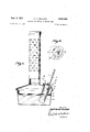
Sept. 1, 1953 c. c. CROCKETT IGNITER AND METHOD OF MAKING SAME Filed Jan. 17, 1948 5 Sheets-Sheet l INVENTOR.
QTTOENEF Sept. 1, 1953 c. c. CROCKETT IGNITER AND METHOD OF MAKING SAME s Sheets-Sheet 2 Jill} 'Filed Jan. 17, 1948 IN VEN TOR.
AUTOZNEV Sept. 1, 1953 c. c. CROCKETT 2,650,438
IGNITER AND METHOD OF MAKING SAME Filed Jan. 17, 1948 v 5 Sheets-Sheet 3 IIIVVENTOR. "BYE.
Sept. 1, 1953 c. c. CROCKETT IGNITER AND METHOD OF MAKING SAME 5 Sheets-Sheet 4 Filed Jan. 17, 1948 'INII/ENTOR. BY
6) a. made Sept. 1, 1953 c. c. CROCKETT 'IGNITER AND METHOD OF MAKING SAME 5 Sheets-Sheet 5 Filed Jan. 17 1948 5227555 iii/15122; 29252515 551155154 555 v INVENTOR.
a. nrroeNEF Patented Sept. 1 1953 UNITED A E T OFF! 25,650,488
MliTHOD OF MAKING s i m ee m caiii.
we: 948. SiiiNWdi? This invention relates to device for'discharging liquid automatically in response to a piedetermined ambient temperature, to'a meth-" d of making the were particularl it relates to such a device wherein the liquid is discharged upon tlitteriiperature of'the ambient air reaching a p'redeterinned 'low and so a' r ranged that the liquidi' ig ted whenreleasied It is an object of th 7 invention to" provide a device of this charaeter ich is inexpensive, simple and reliable,- seawater will operate within ciose limits oi'a" predeterniined tem era:
It is another objector this invention to provide such a device wherein previously stored energy is released in esponse to a critical temperature, for operating theevice;
It is anotherobjet o'fthis 'invention to pro-- vide such a device which' optionally may be rendered inoperative in a simple manner to prevent injury of the parts, as well as toavoid'i accidental operation; and which maybe; conditioned for operation thereafter whenever de-" sired, in response to 'acritiealtemperaturei -t is another object of this inv'entio'nto provide such a device arranged to operate in re sponse to a critical temperature;- which is normally inoperative, an'dwhich may be optionally set for operation, thesett'ingof the deviceserv ing to store energy'which is released atsaidcritical temperature to dperate-the'device:
It is another object Of thisiiivehtidii taprovide such a device which is adjustable to op crate at any desired critical temperaturewithin a predetermined range: h
It is another object of this invention to pro vide such a device wherein the critic'alt'empera ture at which theideviceoperates is determined in a novel manner; g g
It is another object of this" invention to pro vide such a devicefwher in the" reliease' d" liquid has an accuratelypredetermined volume? It is another om-eas er ms invention to pro vide a novel method oimakingsuch adevic'ei It is another'fobi'ect oftliis inventionito' provide a novel method' o'f predetermining" the criti cai operatingt'empe'rature of suchfade'vice.
It is another object 'of this finvention to pro vide such a device optionally adjustablejtoop crate ata critical temperature withina predetermined range, whereintherange isflxed: in a novel manner.
it is another olrjectiiotitl'iis invention to provide such a device wherein the liquid: isiignited upon release:
It is another object or this invention to provide a device for automatically lighting a heater, such as an orchard heater, smudge pot or the like, in response to a critical, low temperature.
This invention possesses many other advantages and has otherobjects which may bermade more easily apparent from a consideration of several embodimentsoi the invention. For this purpose there are shown several forms in the drawings accompanying and forming part of the present specification. These forms will now be described in detail, illustrating the general principles of the invention; but it is to be understood that thisdetailed description is not to be taken in a limiting sense since the scope of the invention is best definedby the appended claims.
By way of example, the device is shown and described as incorporated in anigniter adapted to supply a flame for lighting a smudge pot, orchard heater or the like, when a critical low temperature is reached, including for this purpose means for igniting the discharged liquid. However, it is to be understoodthat the device is'not limited to such use, but may be employed for any purpose requiring discharge of an ac-' curately predeterminedqvolurne of liquid in response to a change in temperature to a critical point.
In the drawings: U V
Figure 1 is a vertical section, partly in elevation; of a conventional orchard heater, showing an igniter incorporating features of the invention, installed for use;
Figure 2 is a fragmentary cross section, taken substantially as indicated by line 2--2 of Figure ,1; I
Figure-j3. is an ;axia1 section, On an la d scale-of the igniter 0f fi ure ,1, partly broken away to reduce thesize of theifigure;
Figure 4 is an elevation as seen from the left oiFigure 3;
Figures 5 andfi are cross sections, taken substantially as indicated by the correspondingly numbered lines on Figure 4;
Figure 'Iis aiview similar to Figure 4, but partly in'section and showinga different adjusted position oithe parts H o 1 Figure: 8 is ,afragmentary section, taken substantially as indicatedby lined-8 of Figure 6, showing another operating position of the partsi Figure 9 isa schematic view, illustrating apparatus useful in performing a step in the manufacturevof the ignitem,
Figure 10 is a fragmentary section showings, detailof the apparatus of Figure 9;
Figure 11 is a fragmentary axial section showing a modified form of the igniter of Figure 3;
Figure 12 is an elevation, as seen from the right of Figure 11;
Figure 13 is an axial section of another modified form of igniter, the intermediate portion of the igniter being shown as broken away to reduce the size of the figure;
Figure 14 is a plan view, seen as looking down on Figure 13;
Figure 15 is an axial section of still another modified form of igniter;
Figure 16 is a cross section, taken as indicated by lines [5-46 of Figure 15; V
Figure 17 is a fragmentary section, illustrating schematically a step in making the igniter of Figure 15; V
Figure 18 is a cross section, taken substantially as indicated by line |8-IB of Figure 17;
Figure 19 is a cross section on an enlarged scale, taken substantially as indicated by line i9--IS of Figure 17;
Figure 20 is an axial section of still another modified form of igniter; and
Figure 21 is a vertical sectional View showing the igniter of Figure 20 installed for use.
Broadly, such an igniter, generally indicated by 4, comprises a tubular shell, such as indicated by the numeral 5 in Figure 3, with an expansible closure 6 at one end, and a closure I at the opposite end adapted to form a discharge opening upon appropriate downward movement of a member '8, extending axially of the shell 5 and mounted on the closure 6. A compression spring 9 urges the member 8 downwardly, a liquid filling l serving to restrain such movement, said liquid being one in which the volume varies consistently with change in temperature, at least within the range of operation of the device.
The liquid filling Iii forms one body of material, a second body of material I being provided closely adjacent, in a cartridge [2. The arrangement is such, that the liquid lfl prevents movement of the member 8 to form an opening through the closure 1 until the ambient temperature reaches a predetermined low. At this point, the member '8 operates in response to spring 9, to release the liquid Ill and to cause it to contact the material ll, these materials being so chosen that a flame is produced by their contact. Optionally operable means are provided for preventing movement of the member 8 to release the liquid, and prevent accidental operation of the de- V108.
As an example of appropriate materials, the
liquid I!) may be isopropyl alcohol and the material I l maybe acompound of about 55 parts of chromic anhydride, 20 parts iodine crystals, and parts potassium nitrate. An automatic igniter employing such materials, arranged to be brought into contact in response to a predetermined low temperature for lighting a smudge pot or the like is disclosed and claimed in applications, Serial No. 719,097 now Patent No. 2,480,397, granted August 30, 1949, and Serial No. 729,784, now Patent No. 2,601,098, granted June 17, 1952, filed respectively on December 28, 1946, and February 20, 1947, in the name of Sydney R. Crockett and assigned to the present inventor. An alternative mixture whach has been found satisfactory for the material H is a compound including about 80 parts chromium trioxide, 15 parts iodine crystals, and 5 parts potassium nitrate.
A conventional type of orchard heater, shown in Figure 1, comprises a shallow reservoir or body I5, containing liquid fuel I6 such as crude petroleum, arranged to be ignited by means of a wick ll, supported with its upper end adjacent the filler opening I8. This opening is closed by a removable cap 19, which is provided with a plurality of vent openings l9-a controlled by a r0- tatable member 20. (See also Figure 2.)
The arrangement is such that the igniter 4 is readily insertible through one of the openings Ill-a, a pointed finger or prong 5-a on the shell being adapted to engage the wick l1 and support the igniter in the opening. Release of the materials producing flame in response to a critical temperature, as previously explained, will ignite the wick l1 and the fuel 16. Thus, when the temperature in the orchard or grove reaches a predetermined dangerous low, the lighting of the heaters, smudge pots, or similar protective devices, occurs automatically and without attention on the part of the grower or an attendant. Since each heater is lighted in accordance with the ambient temperature, only those heaters are lighted where the temperature is dangerously low. On the other hand, the required heaters are lighted at once and without delay, such as would be cccasioned by an attendant being required to light a large number of heaters.
Referring to that form of igniter shown in Figures 3 to 8, the shell 5 may be of any suitable material, such for example as drawn metal tubing having a coefficient of expansion substantially less than that of liquid 10. The expansible closure 6 comprises an annular member B-c, appropriately secured about its periphery in a fluid tight manner in the shell 5 near its upper end. A second annular member 64), of less diameter than the interior of the tube 5, so as to be freely movable therein, is secured in a fluid tight manner on the operating member 8, shown as comprising a rod. The annular members 6-11 and 5-5 are joined in a fluid tight manner by a bellows or Sylphon 6-0, which is preferably of some unelastic material, as will appear hereinafter.
The lower end portion B-a of the bar 8 is of reduced diameter, terminating in a point. A circular member 8-1), freely slideable in the tube 5, is secured on the bar 8 near its lower end, for maintaining the bar substantially coaxial of the tube 5. This member 8-b has several through openings 8-c to permit free passage of the liquid i9 between the space above and below the member 8-1).
The closure 1 comprises a thick disc or plug l-a secured in the lower end of the shell, having a through aperture 1-?) with a counter bore 1-0, which accommodates a gasket 2|, and a member 22 adapted to be easily ruptured by the end of the bar 8. For example, the member 22 may be a thin plate of glass or plastic. A retaining ring 23, having a central aperture 23-12, is secured to the plug l-a by a plurality of screws 24, securing the plat 22 in place against the gasket 2|, and in fluid tight relation with the plug 7-11.
The spring 9 is confined between the movable closure member 6 and an elongated cap 25 telescopically mounted on the upper end of the shell 5. The member 8 extends slidably through an opening 25-a in the top of the cap 25, a pin 26 through the bar 8 serving, by engagement with the top of the cap, to limit upward movement of the cap with respect to the bar.
The wall of cap 25 is provided with a longitudinally extending slot 21 having laterally directed portions 21-a and 21-h respectively at its momma "slot 2 1. Ih'e oa p is When reread downwardly ii i'itil -t'h'e plin"28l1'i""g'es i pperenuontne ld m, ene ca'p bein' med emekwise and lfil'lireii.f0 ove upwardly to dlise the pln 28 tbfiin'gage theofis't zT- 'c cmgllfe 7 Should it ber'ed'iilred-torender theigniter iiioperative atter {itihas beensetga reverse er the foregoing adjusv un'ensonthe-eapas iS-Yblldn'wd. -Thellgniter may set to operas-ve ar imperative as o'ften as necessary, when in the' lnopereltlve condition,"aceciliental operatin Koo rlea'se the liqui'd J H! as by 'a blow, or --j arring is guarded against.
that the cartridge' 'is dtahably securedin place thereby (see Figures B and 'fIn operationfia'fterthe-cap fi lias beemset to release-the member-=8 and enefg'ize the spring -'9, the liquid filling 'lfl supports the member 8, the nuantit'y of liquid being aceurately determined Itof support th membe fl tfithflts 1 lower end 8 a iliightly {'contac ng the' plate f 22 at a; predeterfininedfcritical trnperat'ii "(Figure"7) and" with "the-,end"B- a-spacd abov thepl-ate lit at higher ?"t'en1 peratur'e. When he eni' i'aturedrops beflowthe predeter'mine ems "contractsfallour'ing thei'ne'inbe 8 ward in response to "the fore of spring si and fracture .thei'plate 22; ieleas'irigwthe' liquid filling which the "Ifimbr 8 to: move to the lower limit of its stroke,*brealing the' anip'ule i (see Figure "'8) This"allows -the-liiuiw Hi to contact 1 the material H and ies? previouslyj these mate- "rials arepoffsuch chai'acter as to in'oduoe "flame oncon'tact. MoieparticuIaflm the liquid ll] fisinfla'rnmablefiand"since lit-hows rom the shell 5 1thrdueharestricted opening, the flame "*w'ill persistfor sorndtiriie.
the retaining J IIhisform of igniter is notflhr'iitedto a single" rhus, in Figure 9, :an insulated tank is indicated by the numeral =40, :and has an air tight, removable cover :4 l :Within tank :40- is a loading rack 42, adapted to support a plurality of shells 5. For thisipurpose'theirack 4.2 may have a plurality of openings eachsurrounded :by a collar 'or hjub 42-a, through which-a shell-5 is freely insertible, suitable means, as a 'thumb screw 42-h, being provided for adjustably securing the shell -5 in-the rack.
Thetan'k 4D has a body 43 of the liquid with which-the shellsi are to -be filled, of such depth that the shells 5 when mounted in the rack 42, are submerged. The :tank 40 is arranged to be evacuated by conventional apparatus and is provided with means "for accurately controlling the teniperatureof 'the'liquid 43. Aeonventional refrigerating unit 145, :of suitable capacity and having cooling coils '46 -in' the liquid 43, serves to lower the temperatureof-the liquid, while an immersion heater, "shown "diagrammatically at 41, serves to raise the liquid temperature if; necessary. "Anautomatic temperaturecontroller 48 -'controls'the operation of the refrigerating unit 45 and the immersionheater =41 in accordance with the temperature of th'etliquid 43 as deter- "niined bya feeler bulbi49. .Aumotor driven agitator 50 may be provided-for insuringa uniform temperature throughout'thefbody of liquid-43.
Each shell 5, prior to filling; is provided with -the--expansible closure 6,-carr-yingthe member 8 and the plug "l-a together with thegasket 2 l and frangible closure 22. "Theretainer23 with 'the cartridge clip 33 m n-lace is thenrattached by the screws -zil, the screws=beingadjusted to permit a clearance betweenplate- 23 andplug l-a substantially greater than the-thicknessof the closure 22.
"The spring 9 and cap :25 are also in assembled relation at this timefthe cap i 259beingzpositi0ned with pin 28 intermediate"theends-of the slot 21 so that the member-Bis notsrestrained nor appreciably loaded by the'springiQ.
The member B is then adjuste'di to engage the closure2'2 and push it-and the retainerv23rout- "wardly as far as thescrews 241will. allow. Since,
as previously indicated, the 'bellows 6-0 are collapsible only underi pressure; and no pressure sufficientto compress the bellows i applied thereto at this time, the member-tl :will remain'in this extended position. untilforcedinto the shell .5. The she115'is' then mounted' in therack .42 with the open end upward andwsubmerged in the liquid 43, the ring-(23, inad-dition to being supported, in spaced-relation with thetend ofthe shell 5,bythe member 8, beingsupportedbyi means of a resilient hanger 52 engaging the clipl 33.
With the shellsiarrangedg inlthis mannen'the tank lil is evaouatedeandthe temperature of the liquid 43 reduced to approximately that at :Which the igniters are t to operate, it'being noted that shells will escape through .thaopenings-provided by the spaced plate- 22 @a'nd-ibe replaced by-the 'liquid43. *Since it isimportantthat the evaeuation be-as completeras possible; the-shells may be allowed to remain inthewtank 40-forsome time.
Optionally, theremay betapreliminaryevacuation ain th'e tank with the'Jiquid atgareducedgdepth.
After a suitableainterval the aouum isbroken =and-thetan1eeover 4 his removed. t-Q'IZllQf-SQIGWS? Sylphon 56.
It may be desirable to have the igniter operate at some temperature other than that provided 1 when the shell 5 was filled. This may be accomplished'by providing means for varying the volume of the shell 5'. Thus, for example, if the shell was filled at a temperature of 27, a drop in temperature below 27 would cause the igniter to operate. However, if after filling, the volume of the shell 5 was slightly increased, the critical or operating temperature would be increased, that is the igniter, for example, would operate at a temperature above 27. On the other hand, if the volumev of the shell 5 was decreased after filling, the critical temperature would be decreased, and the device would not operat for example, until the temperature dropped below 26.
Figures 11 and 12 show one type of means which may be provided for adjusting the critical temperature of an igniter such as shown in Figures 3 to 8, and it is to be understood that the structure and mode of operation of this igniter is substantially identical with the previously disclosed form except for the adjusting means. Thus, the shell, indicated by 5-a, has a lateral extension 55 with an elastic bellows or Sylphon 56 secured in a fluid tight manner to the end wall 51 thereof. An adjusting member 58 is threaded through the end Wall 5?, engaging the inner end of the By turning the member 58 in one direction, the bellows is expanded, reducing the Volume of the shell 5-a. By turning the member 58 in the opposite direction, the bellows 56 is allowed to contract due to its elasticity, increasing the volume of the shell. The member 58 may be provided with a pointer 58-00, cooperating with indicia 59 on the Wall 51, to indicate the critical temperature at which the igniter is set in accordance with the adjustment of the member 58.
The critical temperature may also be varied by adjusting the length of the operating member 8, in that form of the invention shown in Figure 3, between the frangible closure 22 and the expansible closure 6. Thus, if the member 8 is shortened after the liquid filling has been supplied at a predetermined temperature, the device will require a greater drop below the predetermined temperature for operation, corresponding to a lower critical temperature; if the member 8 is lengthened the device will operate at a temperature above the predetermined temperature, thus raising the critical temperature to which the device responds.
In Figure 13, an igniter is shown which is substantially identical with that of the form of Figure 3, except for a modified form of operating member 60. This member comprises a lower portion 6| adapted to engage the closure 22 and iii! guided in the shell 5 by a head 62 at its upper end, and a. tubular-upper portion 63 guided in the shell 5 by a head 64 at its lower end, and slidably passing through the aperture 25-a in the cap 25. 'It is to be understood that this tubular portion 63 is joined to the member 6-b of the expansible closure, 6 so as to move therewith to cause the lower portion 6| to rupture the closure 22, in a similar manner to that in which memher 8 of the form of Figure 3 operates.
The upper and lower portions 63 and 61 are joined by an elastic bellows or Sylphon 65, the opposite endsof which are secured in a fluid tight manner respectively to the heads 64 and 62. The bellows 65 urges the member portions 63 and 61 toward each other, such movement being limited by an adjusting member 66 having a portion 61 threadedly engaging the upper portiton 63, and a lower extremity 68 contacting the lower portion 6|. The member 66 extends upwardly and through a cap nut 69 threaded on the outer end of the tubular portion 63 and serving as a bearing for the member 66. This nut also serves to limit outward movement of the cap 25 with respect to the member 63, at the same time permitting inward movement of the cap '25, to set the igniter and energize spring 9.
By rotating the member 66, the efiective length of the member 60 is altered. The member 66 may have a pointer 66-41, cooperating with appropriateindicia ill on the upper end of cap 25 (Figure 14), to indicate the critical temperature to which the igniter is set.
A modified form of igniter is shown in Figures 15 and 16, wherein the tubular shell 15 comprises an appropriately formed sheet, of non-resilient material, rolled and joined in a fluid tight manner along a longitudinal seam 15-a. The upper end portion of the shell is corrugated to form a bellows l6 mounting the upper end closure H for movement toward and away from the frangible closure 18 at the lower end.
The upper closure ll comprises a circular plate with a raised central portion ll-a, joined in a fluid tight manner to the upper end of the bellows 16. The lower end of the shell 15 has an inwardly directed flange 15-!) and a reduced circular extension 15-0 forming an annular recess for mounting the closure 18, which may bee. thin plate of glass or'suitable plsatic. A gasket 19- is interposed between the closure 18 and the flange 15-73, the circular extension being'spun over as at 15-d to secure the plate I8 in fluid tight relation with the flange 15-h.
The operating member comprises a tube 8|, extending axially of the shell 15, having means at its lower end forming a reduced pointed portion 8l-a adapted to rupture the closure 18, and extending through the upper closure 11, being secured thereto in a fluid tight manner. The tube 8| provides an opening for filling and evacuating the shell 15, for this purpose being provided with one or more openings Si-b into the interior of the shell, and being sealed after the filling operation, as at 82.
A compression spring 83 is provided for urging the operatingmember 86 toward the frangible closure 78. This spring 83 is compressed between an apertured disc 84 through which the member 80 is freely slidable, and a guide disc 85 secured on the tube 86 and freely movable in the shell 15. The disc 64 is secured'against axial movement in the shell 15' as'by being mounted in an annular recess 15-e formed in the shell.
As in the-first desqribed form of the invention,
the operating member 88 is urged to rupture the closure 18 by the compression spring 83, and is restrained until a predetermined low temperature is reached by a liquid filling 88. When this temperature is reached, the contraction of the liquid is such as to allow the member 88 to rupture the closure 18 and release the liquid. As before, a cartridge 81, containing a glass ampule 88, is secured to the shell 15 adjacent the lower end thereof as by a spring clip 89. This ampule 88 contains material which upon contact with the liquid 86 will produce flame, the arrangement being such that when the liquid is released from the shell 15, the member 88 under the influence or the spring 83 will travel downwardly and break the ampule 88.
A sleeve 88, secured to the upper closure 11 and extending within the bellows 18, serves to guide the member 88 and prevent lateral distortion of the bellows.
In this form of the invention, the spring 83 is compressed at the time the liquid filling 88 is supplied, as will be described shortly. In order to optionally render the igniter inoperative, an inverted U-shaped member 9| is secured to the upper closure 11, with the legs thereof 9I-a extending downwardly on opposite sides of the bellows 16. The legs SI-a each have an inward extension 9I-b adapted to engage a flange 15-1 formed on the shell 15 below the bellows 18. The parts are so proportioned that with the leg extensions 9I-b seated on the flange 154, the operating member 88 is maintained with its lower extremity 8I-a spaced above the closure 18, re-
gardless of temperature.
The member 9| is of resilient material so that the legs 9 I-a, unless restrained, will spread sufficiently to cause extensions 9I-b to clear the flange 15-1, freeing the member 88 for movement to rupture the closure 18. A ring 82 is provided which encircles the legs SI-a and prevents such spreading, being releasably secured by engaging the offsets 9 I-c in the legs 8 I at.
With the ring 92 in place, the legs 9I-a are maintained in engagement with the flange 15- preventing operation of the igniter. If the legs are released by removal of the ring 92, they will spring apart to clear the flange, and the device is set for operation.
Since as before, the body of liquid 86 determines the temperature at which the igniter operates, the temperature and pressure conditions, which prevail while the shell 15 is filled are quite important. Thus, for filling the shell, apparatus quite similiar to that of Figure 9 may be employed providing an evacuated tank with a body of liquid therein at an accurately controlled temperature, in which the shells 15 are submerged. However, a different type of loading rack is required.
Since the spring 83 is energized, when the device is assembled, means are required for positioning the member 88 so that its lower end 8I-a is within the shell 15 to permit installation of the frangible closure 18, thus compressing the spring 83. Furthermore, the spring 83 must be maintained under proper compression during the operation of filling and sealing the shell 15. For this purpose, a clamp mechanism, generally indicated by the numeral 95 in Figure 17, may be employed.
Referring to Figures 17 and 18, the clamp 95 comprises a lower arm 96 provided with a slot 88% for receiving the shell 15 which is inserted with the flange 15-e below the arm 98, and an upper arm 91 supported in adjustable spaced relation above arm 86 by a nut 98 threaded on a of suitable characteristics.
The tube BI is pinched slightly just below its upper end to accommodate a U-shaped washer I88 (Figure 19) which supports the member 88 on the arm 91. It will be apparent that by appropriate manipulation of the nut 98, the member 88 may be drawn upwardly within the shell 15 as required.
After the installation of the closure 18, the nut 88 is adjusted to permit the end of the member 88 to lightly contact the closure 18, and the shell 15 is supported in a vertical position in the evacuated tank with the open end of tube 8| submerged. After an appropriate interval, the tube M is pinched together to form the closure 82, the device is removed from the liquid 43, and the clamp 95 is .removed from the device. The tube 8| is then cut and soldered at the pinched closure 82,
Beiore removing the clamp 95, it may be desirable to manipulate the nut 98 to withdraw the member 88 sufficiently to permit the legs 9I-a of the safety member 9I, to be moved into engagement with the flange 154 and the retaining ring 92 applied.
Figures 28 and 21 show an igniter I8I having a mode of operation similar to that of the previously discussed forms and employing a molded shell I82 formed, for example of glass or plastic The upper end of the shell I82 has an cxpansible closure comprising a bellows or Sylphon I83 with its upper end molded into an inturned flange I82-sa formed integrally with the shell I82 and its lower end secured to the operating member I 85. The lower end I88 of the member I85 is adapted to fracture the frangible closure I81, which may be conveniently formed by a portion of reduced thickness in an integral transverse wall I82-b at the lower end of shell I82. .An intermediate apertured wall I82-c serves to guide the member I85 axially of the shell I82.
To prevent accidental fracture of the closure I81, a retaining member I89 i provided which 'threadedly engages the upper end of the operating member I85 and has a large head I I8 for engaging the flange I82.-.a at the upper end of the shell I82. By suitable adjustment, the member I89 maintains the member I85 with its lower end I86 spaced above the closure I 81.
This form of the igniter also relies on the contraction oi. a body of liquid III in the shell I82 for operation. In filling the shell I82, the retaining member I89 is adjusted to position the end I88 of the operating member I85 in contact with the closure I81. The shell I82 is then placed in an evacuated tank in an inverted position and with the filling tube II2 submerged in the liquid and upwardly directed. After a suitable interval, the shell is removed from the liquid and the tube I I2 cut oil and sealed as indicated at I I3.
A spring II5 for operating the igniter ml is fixed to depend from an overhanging arm 6-11 of a bracket I I8 secured, for example, to the filling and vent cover II1 of a smudge pot, orchard heater or the like II8, similar to that shown in Figure l.
The cartridge I28 for cooperating with the igniter I88, comprises an ampule I2I containing suitable material for igniting the liquid III, secured as by cementitious material I22 in a ring I23. This ring I23 has a reduced portion I23-a, adapted to enter one of the vent holes I II-a in the cover Ill and providing a shoulder I23-b which supports the cartridge in the cover. The ring I23 also has a plurality of upwardly extending legs I23-c, adapted to fit within an extension I02-d of the shell I02 and seat against the wall I02-b (see Figure 21) In setting the igniter IOI for use, the cartridge I20 is first mounted on the cover II I, and the retaining member I09 is removed from the igniter. The igniter IIlI is then manipulated to cause the spring II to enter the space within the bellows I03 and engage the bottom wall thereof. The igniter is then forced upwardly, compressing the spring II5 until the extension I02-d can pass over the legs I23-c, after which the igniter IN is lowered so as to be supported on these legs, the spring H5 being of such characteristics as to be properly tensioned with the igniter in this position. A guide pin I24, secured to the arm I Iii-a, is provided within the spring II5 to support the spring laterally, and may be arranged for removal if desired to facilitate mounting the igniter.
The operation of this form of igniter is substantially the same as that of the previously discussed forms, that is, the spring I I 5, which is energized when the igniter WI and cartridge I20 are assembled on the cover II'I, urges the member I05 to fracture the frangible member I01, and is restrained by the liquid filling III until the temperature falls below a predetermined low.
Thereafter, the member I05 fracture the member releasing the liquid III, and then fractures the ampule I2 I, the material therein igniting the liquid III upon contact therewith.
Some types of orchard heaters, smudge pots and the like are not provided with wicks such as ll of Figure l for igniting the fuel, the heater H8 of Figure 21 being shown by way of example as of this type. In such cases the cartridge may be provided with a wick, as I25, for carrying the burning liquid from the igniter to the fuel I26 in the heater. This wick I25 is formed of braided asbestos twine, or other suitable material, secured at its upper end in the cementitious material I22 and of suitable length to extend into the fuel I 26.
Brief consideration will show that in all the modifications of the device discussed hereinbefore, the initial step in the operation of the device in response to the temperature reaching the predetermined figure is the release of the liquid filling from the shell, the next step comprising the breaking of the ampule to allow the released liquid to contact the material therein and become ignited. These steps take place in such rapid succession as to occur almost simultaneously. Nevertheless, there are two steps, and the operation of the device can be terminated at the end of the first step by merely omitting the ampule and/or the material therein, the device then serving merely to release a body of liquid for any desired purpose, and forming a complete, operative structure for this purpose.
I claim: 1. An automatic igniter comprising a tubular shell, closures for the opposite ends of said shell, one of said closures being movable toward and away from the other closure, means whereby movement of said movable closure operates to form a discharge opening for the shell, means resiliently urging said movement, a liquid filling in said shell preventing operating movement of said movable closure at ambient temperatures above a predetermined low, and means cooperable with liquid discharged through said opening to produce a'fia'me.
2.'An automatic igniter comprising a tubular shell, closures for the opposite ends of said shell, one of said closures being movable toward and away from the other closure, a member extending between said closures for opening the other closure to form said opening in response to movement of said movable closure, means resiliently urging said movement, a liquid filling in said shell maintaining said closures so spaced at a predetermined temperature that said member contacts both closures, whereby a drop in the ambient temperature below said predetermined low causes movement of the movable closure to form said opening, and means cooperable with the liquid discharged through said opening to produce 3. In an automatic igniter: means forming a pair of bodies of material adapted to ignite and produce fiame upon contactin each other, at least one of said materials being a liquid; means enclosing said liquid, including a frangible wall adjacent the other material; and a member movable in response to contraction of said liquid, for fracturing said wall, releasing said liquid and causing said materials to contact.
4. In an automatic igniter: means forming a pair of bodies of material adapted to ignite and produce flame upon contacting each other, at least one of said materials being a liquid; means enclosing said liquid, includin a frangible wall adjacent the other material; a member movable in response to contraction of said liquid for fracturing said wall at a predetermined temperature, to release said liquid and cause it to contact the other material; and means adjustable to cause said fracturing member to operate at different temperatures.
5. In an automatic igniter: means forming a pair of bodies of material adapted to ignite and produce flame upon contacting. each other, at least one of said materials being a liquid; means enclosing said liquid, including a frangible wall adjacent the other material; a member mounted for movement to fracture said wall; means adapted to resiliently urge said member to fracturing position; means whereby said liquid prevents fracturing movement of said member at ambient temperatures above a predetermined low; and means optionally operable to prevent fracturin movement of said member or to energize the means to resiliently urge said member.
6. In an automatic igniter: means forming a pair of bodies of material adapted to ignite and produce flame upon contacting each other, at least one of said materials being a liquid; means enclosing each of said bodies, each of said en'- closing means comprising a frangible wall, said walls being closely spaced; a member mounted for movement to fracture said wall; means resiliently urging said member to fracturing position to release said materials for contact; and
'means whereby said liquid prevents fracturing 05' movement at ambient temperatures above a predetermined low.
7. In an automatic igniter: means forming a sealed container; a body of liquid substantially entirely filling said container, means in said container operating responsive to a change in volume of said liquid caused by a variation in term perature for releasing said liquid from said con tainer; means for varying the volume of said container to vary the temperature response of the liquid releasing means, and, means cooperable 13 withl iquid releasedfrom said container to produce a name;
8. In an automatic igniter; means forming a sealed container, havin an expansibleelement varying the volume thereof, and means adapted to form a discharge opening; abody of liquidsub stantially entirely filling said container; a member engaging said element for movement therewith and adapted, upon predetermined movement of said element, to cause the discharge forming means to release said liquid; means resiliently urging movement of said element to reduce the volume of said container, said liquid preventing movement of said element in volume decreasing direction until the temperature of said liquid falls below a predetermined temperature; and means cooperable with liquid released from said container to produce a fiame.
9. In an automatic igniter: a hollow shell; means forming closures respectively for opposed openings in the shell; means mounting one of said closures for movement toward and away from the other closure; a member extending lengthwise of the shell between said closures adapted to open one of said closures to provide a discharge opening; means resiliently urging said closures toward each other; a liquid in said shell for maintaining said closures in definite spaced relation at a predetermined temperature, and responsive to a fall in temperature to release said closures to approach, whereby said member opens said one closure for discharging said liquid; means for adjusting the length of said member to vary the temperature at which said liquid prevents movement of said closures to release the liquid; and means cooperable with said liquid when released to produce flame.
10. The method of forming an automatic liquid discharge device which comprises: providing a hollow shell having a pair of openings, with means forming closures for said openings, and operating means which in response to movement of one of said closures in response to a change in volume of said shell, forms a discharge opening for the contents of the shell, which comprises; maintaining said movable closure at a definite position in the shell, providing an opening into the shell, comprising a tube extending from the shell, submerging said shell in a body of liquid at a predetermined temperature, said shell and said tube being upwardly directed, with the mouth of said tube below the surface of the liquid, and sealing said tube.
11. In an automatic liquid discharge device: an expansible tubular shell, closed at its opposite ends; a member extending lengthwise of the shell secured to one end thereof, and adapted to rupture the opposite end in response to contraction in the length of said shell; means resiliently urging said shell to contract; and a liquid filling in said shell maintaining said shell against contraction to cause rupture of said op posite end above a predetermined temperature.
12. In an automatic liquid discharge device: an expansible tubular shell, closed at its opposite ends; a member extending lengthwise of the shell secured to one end thereof, and adapted to rupture the opposite end in response to contraction in the length of said shell, at least a portion of said member being tubular and extending through said end to provide a filling opening sealed after filling; means resiliently urging said shell to contract; and a liquid filling in said shell maintaining said shell against contraction to 14 cause rupture of said opposite endab'ov'e a predetermined temperature.
13. In an automatic liquid discharge device: means enclosing a body of liquid 'including a frangible wall; a member mounted for movement to fracture said wall and release said liquid; means resiliently urging said member to fracturing position; and means whereby said liquid prevents fracturing movement of said member at ambient temperatures within a range having a predetermined end point, and releasing said member tor movement upon the temperature reaching said end point.
14. An automatic liquid discharge device comprising a tubular shell, closures for the opposite ends of said shell, one of said closures being movable toward and away from the other closure, means whereby movement of said movable closure operates to form a discharge opening for the shell, means resiliently urging said movement, a liquid filling in said shell preventing operating movement of said movable closure at ambient temperatures within a range having a predetermined end point, and releasing said closure for movement upon the temperature reaching said end point, and means adjusting the effective volume of said shell.
15. The method of forming an automatic liquid discharge device which includes a hollow shell having a pair of openings, means forming closures for said openings, and means which upon movement of one of said closures in response to a change in volume of said shell, forms a discharge opening for the contents of the shell, which comprises; maintaining said movable closure at a definite position in the shell, providing an opening into the shell, filling said shell with liquid at a predetermined temperature, and sealing said opening while immersed in liquid.
16. The method of forming an automatic liquid discharge device which includes a hollow shell for enclosing the liquid, and means oper-- ating in response to a change of volume of liquid in said shell as effected when the temperature of the liquid varies from a predetermined temperature, to form a discharge opening for the contents of the shell, which method comprises; providing an opening into the shell, filling the shell by submerging it in a liquid at a predetermined temperature approximating that at which said discharge opening will be formed, and sealing said opening while it is submerged.
17. The method of forming an automatic liquid discharge device which includes a hollow shell for enclosing the liquid, a force applying means, and means which is operated by said force applying means only in response to a temperature effected change in volume 01. liquid in said shell, to form a discharge opening through a portion of the shell, which method comprises; providing an opening into the shell, filling the shell by submerging it in a liquid at a temperature approximating the temperature at which the discharge opening will be formed, and sealing said opening while said force applying means is inoperative and while maintaining the shell submerged and said discharge opening forming means in contact with the portion of the shell in which the discharge opening is to be formed.
18. The method of forming an automatic liquid discharge device which includes a hollow shell having a pair of openings, a movable closure and a frangible closure for said openings, spring loaded means operating upon movement of said movable closure in response to a temperature effected change in volume of said liquid, to rupture said frangible closure and form a discharge opening for the contents of the shell, which comprises; providing an opening into the shell, removing the spring load from said rupturing means, filling the shell by submerging it in a liquid approximating the temperature at which said rupturing means will be operative to restore the frangible closure, securing said frangible closure to the shell to seal said opening while the opening is submerged and said frangible closure in contact with said rupturing means.
CYRIL CHARLES CROCKETT.
References Cited in the file of this patent UNITED STATES PATENTS Number Name Date Lighthipe Jan. 6, 1914 Bray Jan. 20, 1920 Fernandez Sept. 1, 19 6 Martin-Hurst et al. May 28, 1940 Crockett r Aug. 30, 1949:
Priority Applications (1)
| Application Number | Priority Date | Filing Date | Title |
|---|---|---|---|
| US2888A US2650488A (en) | 1948-01-17 | 1948-01-17 | Igniter and method of making same |
Applications Claiming Priority (1)
| Application Number | Priority Date | Filing Date | Title |
|---|---|---|---|
| US2888A US2650488A (en) | 1948-01-17 | 1948-01-17 | Igniter and method of making same |
Publications (1)
| Publication Number | Publication Date |
|---|---|
| US2650488A true US2650488A (en) | 1953-09-01 |
Family
ID=21703036
Family Applications (1)
| Application Number | Title | Priority Date | Filing Date |
|---|---|---|---|
| US2888A Expired - Lifetime US2650488A (en) | 1948-01-17 | 1948-01-17 | Igniter and method of making same |
Country Status (1)
| Country | Link |
|---|---|
| US (1) | US2650488A (en) |
Cited By (1)
| Publication number | Priority date | Publication date | Assignee | Title |
|---|---|---|---|---|
| US4519774A (en) * | 1984-03-29 | 1985-05-28 | Shedd Clifford M | Temperature actuated burner igniter |
Citations (5)
| Publication number | Priority date | Publication date | Assignee | Title |
|---|---|---|---|---|
| US1083749A (en) * | 1911-07-24 | 1914-01-06 | James A Lighthipe | Automatic fire-starting device. |
| US1328788A (en) * | 1918-03-04 | 1920-01-20 | Nelson H Bray | Automatic igniter for orchard-heaters |
| US2052925A (en) * | 1935-11-14 | 1936-09-01 | Fernandez Serafin Santeago | Fire lighter |
| US2202705A (en) * | 1937-10-06 | 1940-05-28 | British Thermostat Co Ltd | Temperature control device for internal combustion engines |
| US2480397A (en) * | 1946-12-28 | 1949-08-30 | Cyril Charles Crockett | Smudge pot igniter |
-
1948
- 1948-01-17 US US2888A patent/US2650488A/en not_active Expired - Lifetime
Patent Citations (5)
| Publication number | Priority date | Publication date | Assignee | Title |
|---|---|---|---|---|
| US1083749A (en) * | 1911-07-24 | 1914-01-06 | James A Lighthipe | Automatic fire-starting device. |
| US1328788A (en) * | 1918-03-04 | 1920-01-20 | Nelson H Bray | Automatic igniter for orchard-heaters |
| US2052925A (en) * | 1935-11-14 | 1936-09-01 | Fernandez Serafin Santeago | Fire lighter |
| US2202705A (en) * | 1937-10-06 | 1940-05-28 | British Thermostat Co Ltd | Temperature control device for internal combustion engines |
| US2480397A (en) * | 1946-12-28 | 1949-08-30 | Cyril Charles Crockett | Smudge pot igniter |
Cited By (1)
| Publication number | Priority date | Publication date | Assignee | Title |
|---|---|---|---|---|
| US4519774A (en) * | 1984-03-29 | 1985-05-28 | Shedd Clifford M | Temperature actuated burner igniter |
Similar Documents
| Publication | Publication Date | Title |
|---|---|---|
| US3309890A (en) | Refrigerated disposable container | |
| US3253611A (en) | Controller for cryogenic liquids | |
| US2853126A (en) | Stoves and like apparatus using liquefied gas | |
| US2097585A (en) | Valve for pressure cookers, sterilizers and the like | |
| US3724360A (en) | Thermal indicator | |
| US2650488A (en) | Igniter and method of making same | |
| US3407624A (en) | Apparatus for chilling vessels | |
| US3241713A (en) | Thermal safety device for aerosol containers | |
| US2489620A (en) | Lighter | |
| US2135404A (en) | Device for breaking bottles | |
| US2790378A (en) | Egg boiler | |
| US2493759A (en) | Production of carbon dioxide snow | |
| NO172263B (en) | JOULE-THOMSONKJOELER | |
| US2206949A (en) | Pressure lamp or stove | |
| US2451151A (en) | Pumping volatile liquids | |
| US1434542A (en) | Thermostatic control apparatus | |
| US2480397A (en) | Smudge pot igniter | |
| US1943480A (en) | Automatic sprinkler | |
| US2149420A (en) | Stove | |
| US1847844A (en) | Level indicator | |
| US875481A (en) | Safety-closure for receptacles. | |
| US2290826A (en) | Draft regulating device for orchard heaters | |
| US22465A (en) | Burster foe | |
| USRE16132E (en) | Automatic sprinkler | |
| US2335999A (en) | Pyrometer |