US2649813A - Power and manually operated gear shift - Google Patents
Power and manually operated gear shift Download PDFInfo
- Publication number
- US2649813A US2649813A US105472A US10547249A US2649813A US 2649813 A US2649813 A US 2649813A US 105472 A US105472 A US 105472A US 10547249 A US10547249 A US 10547249A US 2649813 A US2649813 A US 2649813A
- Authority
- US
- United States
- Prior art keywords
- clutch
- motor
- switch
- power
- shift
- Prior art date
- Legal status (The legal status is an assumption and is not a legal conclusion. Google has not performed a legal analysis and makes no representation as to the accuracy of the status listed.)
- Expired - Lifetime
Links
Images
Classifications
-
- F—MECHANICAL ENGINEERING; LIGHTING; HEATING; WEAPONS; BLASTING
- F16—ENGINEERING ELEMENTS AND UNITS; GENERAL MEASURES FOR PRODUCING AND MAINTAINING EFFECTIVE FUNCTIONING OF MACHINES OR INSTALLATIONS; THERMAL INSULATION IN GENERAL
- F16H—GEARING
- F16H63/00—Control outputs from the control unit to change-speed- or reversing-gearings for conveying rotary motion or to other devices than the final output mechanism
- F16H63/02—Final output mechanisms therefor; Actuating means for the final output mechanisms
- F16H63/30—Constructional features of the final output mechanisms
- F16H63/304—Constructional features of the final output mechanisms the final output mechanisms comprising elements moved by electrical or magnetic force
-
- Y—GENERAL TAGGING OF NEW TECHNOLOGICAL DEVELOPMENTS; GENERAL TAGGING OF CROSS-SECTIONAL TECHNOLOGIES SPANNING OVER SEVERAL SECTIONS OF THE IPC; TECHNICAL SUBJECTS COVERED BY FORMER USPC CROSS-REFERENCE ART COLLECTIONS [XRACs] AND DIGESTS
- Y10—TECHNICAL SUBJECTS COVERED BY FORMER USPC
- Y10T—TECHNICAL SUBJECTS COVERED BY FORMER US CLASSIFICATION
- Y10T74/00—Machine element or mechanism
- Y10T74/18—Mechanical movements
- Y10T74/18056—Rotary to or from reciprocating or oscillating
- Y10T74/18216—Crank, lever, and slide
- Y10T74/18224—Rack connections
-
- Y—GENERAL TAGGING OF NEW TECHNOLOGICAL DEVELOPMENTS; GENERAL TAGGING OF CROSS-SECTIONAL TECHNOLOGIES SPANNING OVER SEVERAL SECTIONS OF THE IPC; TECHNICAL SUBJECTS COVERED BY FORMER USPC CROSS-REFERENCE ART COLLECTIONS [XRACs] AND DIGESTS
- Y10—TECHNICAL SUBJECTS COVERED BY FORMER USPC
- Y10T—TECHNICAL SUBJECTS COVERED BY FORMER US CLASSIFICATION
- Y10T74/00—Machine element or mechanism
- Y10T74/18—Mechanical movements
- Y10T74/18888—Reciprocating to or from oscillating
-
- Y—GENERAL TAGGING OF NEW TECHNOLOGICAL DEVELOPMENTS; GENERAL TAGGING OF CROSS-SECTIONAL TECHNOLOGIES SPANNING OVER SEVERAL SECTIONS OF THE IPC; TECHNICAL SUBJECTS COVERED BY FORMER USPC CROSS-REFERENCE ART COLLECTIONS [XRACs] AND DIGESTS
- Y10—TECHNICAL SUBJECTS COVERED BY FORMER USPC
- Y10T—TECHNICAL SUBJECTS COVERED BY FORMER US CLASSIFICATION
- Y10T74/00—Machine element or mechanism
- Y10T74/19—Gearing
- Y10T74/19219—Interchangeably locked
- Y10T74/19242—Combined gear and clutch
- Y10T74/19247—Preselector
-
- Y—GENERAL TAGGING OF NEW TECHNOLOGICAL DEVELOPMENTS; GENERAL TAGGING OF CROSS-SECTIONAL TECHNOLOGIES SPANNING OVER SEVERAL SECTIONS OF THE IPC; TECHNICAL SUBJECTS COVERED BY FORMER USPC CROSS-REFERENCE ART COLLECTIONS [XRACs] AND DIGESTS
- Y10—TECHNICAL SUBJECTS COVERED BY FORMER USPC
- Y10T—TECHNICAL SUBJECTS COVERED BY FORMER US CLASSIFICATION
- Y10T74/00—Machine element or mechanism
- Y10T74/19—Gearing
- Y10T74/19219—Interchangeably locked
- Y10T74/19251—Control mechanism
Definitions
- This invention relates generally to transmission gears for automotive vehicles.
- ,It has for its object a transmission gearing in which the power to drive the vehicle is trans mitted through at least two selectable paths, or gear trains, each of whichincludes a shiftable element, as a clutch, the shiftable element in one train being power shifted, and the shiftable element in the other train being shifted independently of the former element or driver controlled, or manually shifted, and; in addition, control means operated by the shifting mechanism of the manually shiftable element or clutch to control the power shifting of the power shiftable element or clutch out of shifted position preliminary to the shifting in of the manually shiftable element, and to control the shifting in of the power shiftable element until the manually shiftable element has been shifted out.
- the invention is here shown as embodied in an auxiliary transmission which may be attached to, or used in conjunction with, a regular or main transmission having the usual gear shifts effected by a gear shifting lever in the usual way. It is intended for duty in heavy vehicles where at times it is necessary to utilize an emergency or sub low gearing in connection with the regular gearing, and the invention lies in an easy way for efiecting the shift into and out of the sublow gearing without modifying the shifts in the main gear box.
- the power shiftable element or. clutch is in neutral position when not in clutched position so that a power take-off can be used when the vehicle is stationary.
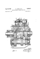
- Figure 1 is a longitudinal sectional view of a gearing embodying this invention.
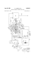
- Figure 2 is a diagrammatic .view of the operating system therefon
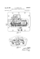
- Figure 3 is a' plan view, partlyin section, looking downwardly in Figure 1.
- Figure 4 is a fragmentary plan viewof the reversing means or switches for the reversible motor.-
- the invention lies, in, its general aspect, in a transmission gearing having a power shiftable change speed element, as a clutch, shifting mechani sm therefor including o a, reversible motor, a
- the transmission mechanism comprises, more specifically, input and output shafts, gear trains between ,the shafts, each train comprising an element, as a clutch, shiftable into and out of op'erativeor motion transmitting position, the elements being alternately operable into operative position, that is either element is in operative position while the other is out, power mechanism including a reversible motor for shifting one only of said elements, asecond mechanism for shifting the other of said elements including a shift member, the second mechanism being usually driver controlled or manually operable independently of the power operated mechanism, and, meansoperated by the shift member of the secondmechanism to successively reverse the motor .of the power mechanism to shift out the engaged power shiftable element and cut out the fiow-of-power to the motor-while the shiftable member of the second mechanism is being actuated from starting position on its shifting in movement and the element shifted by the second mechanism is short of operative motion transmitting engagement, and to successively shift out the element operated by the second mechanism and again out in the power to the motor upon moving of the shift member
- V Land 2 designate the input and output shafts of, the gearing mounted in axialalinement in suitable bearings in a gear box 3
- 4 is a countershaft mounted in the gear box.
- the element or clutch I is slidably splined on the hub of a gear ll rotatably mounted on the output shaft and is shiftable, as to the left, into engagement with a clutch face
- the gear I! meshes with a gear [3 on the countershaft so that when the element or clutch I0 is in engaged position, the output shaft 2 is driven through a reduction train of gears including the gears I, 8, countershaft 4, gears l3 and II.
- the clutch or element 5 is power shifted, and the clutch H] is shifted independently of the power shift by other shift mechanism. It is usually manually shifted.
- the power utilized for shifting the clutch 5 is, in this embodiment of our invention, electrical and comprises a reversible electric motor I4 mounted in a casing l5 which is suitably mounted on the top of the gear box 3, the motor having a feed screw device It actuated by its rotor which feed screw, through mechanism to be described, operates a nut H on the screw device, and the motion of the nut is transferred to a fork 20 on a shift rod l9 suitably mounted in the casing l5 and connected to the shiftable clutch 5.
- the mechanism for shifting in the clutch l0 comprises a shift member as a rod 2
- is here shown as operated by a manual lever 23, Figure 2, which is normally in starting position and is movable from starting position to an intermediate or neutral position and finally into shifted position.
- the rod when moving from starting position, shifts relatively tothe fork 22 and in so doing, the lever 23 moves to neutral position Without shifting the fork 22 where, through a suitable coupling, the fork 22 is clutched to the rod 2
- the starting position of the lever 23 is for convenience called the preselect position because then the clutch 5 is operable to be shifted from direct drive position to indirect drive position, or from indirect drive position to direct drive position.
- the clutch 5 is first shifted by the motor to neutral position and the motor deenergized and continued movement of the lever 23 from neutral position shifts the clutch l0 into engagedposition. 1
- the power system for the motor comprises a switch 25 carried by the gear shifting lever 26 of the main gearbox, this switch controllin two feed circuits to the motor l4. It is operated by a button or plunger 21.
- One of the circuits supplies current to the reversible motor
- the other of the feed circuits 4 supplies current to said reversible motor causing it to rotate in the direction to shift the clutch 5 out of indirect drive to the left to the direct drive position.
- the switch 25 is preset by the button 27 to preselect one or the other of the direct drive, or the indirect second speed positions.
- the clutch 5 is in the position shown in Figure 1, that is, shifted in to the left.
- the shift was made to the left upon depression of the engine clutch pedal 28 by the current passing from the battery or source of supply 29, through an overload relay switch 3
- the motor is actuated in one direction to turn the screw device H5 in one direction to shift the nut H to the left and hence, shift in the clutch 5 in direct drive.
- 'i opens the cut-out switch 38 and incidentally closes the switch 383,'and also reverses the reversing switch 43 in one direction into engagement with the contact 44, similar to the contact 39.
- the driver operates the shift lever 23 for the emergency low shift rod 2
- the clutch 5 is then shifted back to its preselected shifted position, or in the left hand position, Figure 1, because current then, flows through the power shift circuit which has no neutral position. As it reaches this position, reversing switch 43 is again reversed to the position shown in Figure 2. Because of the construction of the motion transmitting means between the nut H and the shifting fork 2B, the clutch can continue its shifting in movement due to a spring arrangement in the clutch mechanism after the reversing switch 43 reverses. A similar operation takes place when the plunger 21 of the selecting switch 25 is set in second position to shift the clutch 5 to the right to clutch the gear 6 to the output shaft 2, except that the current is supplied to the motor through the cut-out switch 380 and wire 53 instead of through switch 38.
- the motion transmitting means between the nut l1 and the block consists of two levers 60 and 6
- the motion of the levers 60, BI is transferred one to the other through a torsion spring 61 coiled about the shaft 62 and having arms at its ends thrusting against the levers respectively.
- the reversing switch is of the snap, or overthe-center, or tog le type, of any conventional construction.
- the pin 10 on nut l'i has been shifted to the right to engage shoulder 12 of two spaced shoulders I 12, on the reversing switch. Further movement to the right will cause the reversing switch tobe shifted over to the left toward contact 39.
- the movement of the switch to the left loads a spring 13, one arm 730 of which is anchored to the switch 43 eecentric to the axis thereof, and the other arm of which is pivoted to a toggle link 14 at 140.
- Interlocking means prevents the clutch
- the selecting switch 25 is in indirect drive or second position, the operation is the same except the current is supplied to the motor l4 through the wire 83 and cut-out switch or contact 380.
- the interlocking mechanism for preventing shifting of the clutch 5 into either of its engaged positions while the clutch I0 is in engaged position, and for preventing shifting in of the clutch 9 until the clutch 5 has been shifted out of either of its engaged positions to neutral position may be of any suitable type, it being here shown as a transversely extending, axially shiftable rod 15, Figure 2, having one end for entering a notch 16 in the shift rod 2
- and I9 is such that when one end of the rod 15 is in the notch 16 and the other end is engaged with the periphery of the rod IS, the rod 2
- a suitable spring pressed poppet 18 coacts in the usual manner with notches .9 in the rod IE) to steady it when in any one of these shifted positions and especially to locate the rod I9 and its fork in neutral position when the rod 15 is in the notch 11.
- the energizing current for the motor flows as follows:
- the clutch pedal 28 is depressed to close the switch 32 preliminary to the shifting in of the clutch 5 to the right into second position; from the battery 29 to the closed switch 32, switch 34, which is engaged with contact 35, thence to preselecting switch 25, through wire 80, the cut-out switch contact 380, contact 44 and branch wire 53, to the motor, thus actuating the motor M to shift the nut l1 and the fork 28 to the right from neutral, shifting in the clutch 5 to the right to clutch the gear 6 to the output shaft 2, the shifting in operation reversing the reversing switch 43 so that it will be in such position to again reverse the motor in case the shift lever 23 is operated to shift in the-clutch it.
- the clutch pedal 28 is operated preliminary to making the shift, thus closing the switch 52 so that the current passes from the battery as through the switch 32, the switch 34, to the contact 5i, which has been closed by reason of the shifting of the rod 2!, or the shift lever 23 to neutral position, thence to the reversing switch 43, contact 39 and branch wire 40 to the other terminal 4! of the reversible motor, thus reversing the motor and shifting out the clutch 5 to the left to neutral position, the reversing switch coming to its neutral position during this operation.
- the switches 35 or 385 and the switch 43 are respectively a cut-out switch and a reversing switch in the feed circuit of the motor controlled and timed in their operation by the motor, or the nut ll actuated by the feed screw on the rotor of the motor.
- the cut-out switch 38 is in the direct drive circuit selected by the selecting switch 25 and being closed when the clutch 5 is in neutral position.
- the switch 38 is shifted out to stop the motor at the end of the shifting in movement of the clutch 5 by the nut I7, and the reversing switch 43 shifts to reverse position by the nut ii at the beginning of the shift-in movement of the clutch 5.
- the cut-out switch 38 is opened at the end of the shifting in movement of the clutch 5 and the reversing switch 43 reshifted into re-reversing or obverse position at the beginning of the shifting in movement of the clutch 5.
- the cut-out switch 38 is in the direct drive circuit controlled by the selecting switch 25, and the cut-out switch 330 is in the indirect drive circuit controlled by the selecting switch 25.
- the switch 34 is a driver controlled switch operated by the manual shift lever 23 on the shift rod 20 for the clutch Ill and controlling the energization and timing of the motor [4 and the shifting of the clutches 5 and ill.
- the fork 22 for the clutch I8 is coupled to the shift rod 2i by a coupling which permits the rod to be first shifted through a lost motion relatively to the fork while the rod is being shifted from preselected position to neutral position and then pick up the coupling to shift the clutch Ill into engaged position.
- the coupling also permits shifting out of the clutch ill in the reverse order.
- the coupling consists of a radial poppet 8!, Figure 1, located in the hub 41 of the fork 22 and pressing radially against the periphery of the rod 2!, and located to enter a notch 82 in the rod when the rod has been shifted, as to the left, from starting or preselected position into neutral position.
- the clutch 5 is provided with a synchronizer of conventional construction.
- the clutch 5 is here shown as slidably plined on a collar 84 keyed to the output shaft 2 and as having clutch teeth and B! at itsopposite ends, the clutch teeth 86 being peripheral and coacting with complemental internal teeth 88 on the gear I and the clutch teeth 8'! being the right hand ends of the splines of the clutch '5 and coacting with peripheral clutch teeth 89 on the hub of the gear 6.
- the synchronizer is a sleeve mounted in the usual manner-concentric with the clutch 5 and having the usual circumferential rocking movement within limits. The sleeves is connected to the clutch 5 to rotate therewith by the usual slots '92 through which radially extending spokes 9
- the sleeve is provided with friction faces 93, 94, at its opposite ends for coacting with complemenal faces on the gears l and B respectively.
- the friction face at one end first engages the complemental face on the gear I or (5, thus effecting the synchronization and stopping the shifting-in of the clutch-5 until the speeds synchronize when the shifting-in force overcomes the usual yielding connection, not shown, between the clutch 5 and the synchronizer sleeve 95, whereupon the teeth of the clutch 5 shift into interlocking engagement with the complemental teeth without clashing.
- the spring 6! is purposely made weak enough, it yields and stores up power under the influence of the motor actuated screw l6 and then when synchronization occurs, the spring completes the shifting-in after the motor is stopped by the shifting of the cut-out switch 38 or 385, as before described. If however, the spring is made sufficiently strong to stall the motor before the cut-out switch 38 or 380 is opened, the motor remains stalled until synchronization occurs when the motor resumes its operation until the nut (I has resumed its movement under the motor far enough to complete the shifting-in of the clutch 5.
- the driver can easily shift to another gear, as emergency low gear, without operating the gear shifting lever of the main gear box, and a shift into the additional or emergency gear can be made by merely shifting the lever 23, and all other operations, such as the power shifting of other clutches or gears that must be shifted out during the shifting of the emergency gear takes place automatically by the shifting of the lever 23, or the shift rod 2i, both when the shift is being made into and out of the emergency gear.
- each train comprising an element shiftable into and out of operative motion transmitting position, said elements being" alternately operable relatively to each other into and out of operative position
- power mechanism including a reversible motor for shifting one only of said elements in reverse directions, a power system for the motor, a second mechanism for shifting the other element only comprising a shift member, power controls in the power system including cut-out and reversing power control members operated successively by the reversible motor when at the beginning and at the end of the shifting operations of the motor and including also an interlock between said mechanisms and operable thereby to maintain the operation of the shiftable elements by the two shift mechanisms in alternate relation.
- a second mechanism for shifting the other ele-' ment comprising a shift member
- power controls in the power system including a control memberv operated by the shift member of the second mechanism, .and cut-out and reversible power controls operated successively by the reversible motor when at the beginning and at the end of the shifting operations of the motor, and an interlock between said mechanisms and operable thereby to maintain the operation of the shiftable elements by the two shift mechanism in alternate relation
- the motor being a reversible electric motor and the power system comprising an electric feed circuit
- the control member operated by the shift" member of the second mechanism being a'switch
- the control members operated by the motor being a revers ing :switch and a cut-out switch closed during the shifting operations
- the reversing and cutout switches being operable to closed and open positions respectively successively by the motor during the beginning of the shifting-in operation and the end of the shifting-in operation
- thecut-out switch and'the reversing switch being movable to
- a transmission gearing input and output shafts, a transmission path between the shafts comprising an element shiftable into and out of operative motion transmitting position
- power shift mechanism including a reversible electric motor having a rotor formed with feed screw means and a nut movable lengthwise of the feed screw during turning of the feed screw, a main feed circuit for the motor having branches leading to opposite terminals of the motor, a reversing switch operable from neutral position to connect either branch in the main circuit, a normally closed cut-out switch in the main circuit, a motion transmitting connection operated by the nut to successively operate the reversing switch from neutral to reverse position and the cut-out switch to open position during the beginning and end respectively of the travel of the nut to engage the power shiftable element, and
- gear trains between the shafts having respectively first and second motion transmitting elements shiftable into and out of operative motion transmitting position, said elements being alternately operable relatively to each other into and out of operative position, power mechanism for shifting one only of said elements, a second mechanism operable independently of the power mechanism for shifting the other of said elements, the power mechanism including a reversible' motor, a shift member operated thereby and, a fork connecting the power shift member and the power shiftable element, the second mechanism including a second shift member and a' fork connecting it and the second shiftable element, the second shiftable element being normally in inoperative or disengaged position, a power system for the motor, a control element in the power system shiftable for conditioning the motor for operation in opposite directions reversible by the motor during its operation in one direction and reversible in the opposite direction by the motor when the motor is being actuated in the opposite direction, and a second control element in the power system in series with the first control element in the power system
- a transmission gearing, input and output shafts gear trains between the shafts having respectively first and second motion transmitting elements shiftable into and out of'operative motion transmitting position, said elements being alternately operable relatively to each other into and out of operative position, power mechanism for shifting one only of said ele-' ments, a second mechanism operable independently of the power mechanism for shifting the other of said elements, the power mechanism including a reversible motor, a shift member operated thereby and a fork connecting the power shift member and the power shiftable element, the second mechanism including a second shift member and a fork connecting it and the second shiftable element, the second shiftable element being normally in inoperative or disengaged position, a power system for the motor, a control element in the power system shiftable for conditioning the motor for operation in opposite directions reversible by the motor during its operation in one direction and reversible in the opposite direction by the motor when the motor is being actuated in the opposite direction, and a second control element in the power system in series with the first control element in the power
- gear trains between the shafts having respectively first and second motion transmitting elements shiftable into and out of operative motion transmitting position, said elements being alternately operable relatively to each other into and out of operative position, power mechanism for shifting one only of said elements, a second mechanism operable independently of the power mechanism for shifting. the other of said elements, the power mechanism including a reversible motor, a shift member operated thereby and.
- the second mechanism including a second shift member and'a fork connecting it and the second shiftable element, the second shiftable element being normally in inoperative or disengaged position, a power system for the motor, a control element in the power system shift-v able for conditioning the motor for operation in opposite directions, said control element being reversible by the motor during its operation in one direction and reversible in the opposite direction by the motor when the motor is being actuated in the opposite direction, and a second control element in the power system in series with the first control element and operable by the shift member of the second mechanism into power conducting position, a power control in series with the second control element normally out of power conducting position, and an operator operated part operable preliminary to gear changing operations and connected to the last control to shift it into power conducting. position.
- gear trains between the shafts having respectively first and second motion transmitting elements shiftable into and out of operative motion transmitting position, said elements being alternately operable relatively to each other into and out of operative-position, power mechanism for shifting one only of said elements, a second-'mechanismoperable independently of the power mechanism for shifting the other of said elements, the power mechanism including a reversible motor, a shift member op-,- erated thereby and a fork connecting the power shift member and the power shiftable element, the second mechanism including a second shift member and a forkconnecting it and the second shiftable element, the second shiftable element being-normally in inoperative or disengaged position, a power system.
- a control element in the power system shiftable by the conditioning-of the motor operation in reverse direction therein reversible by the motor during its operation. in one direction and reversible in the opposite direction by, the motor when the motor-isbeing actuated-in the opposite direction, and asecond control element in the power system in series with the first control element and operable by the shift member of the second mechanism into power conducting position, and an interlock between the shift members and operable thereby to lock either shift member from complete shifting-in move,- ment when the other shift member is, inoperative position and thereby maintaining the a1- ternate shifting of the shiftable elements.
Landscapes
- Engineering & Computer Science (AREA)
- General Engineering & Computer Science (AREA)
- Mechanical Engineering (AREA)
- Gear-Shifting Mechanisms (AREA)
Description
Aug. 25, 1953 J. BARTH ET AL 2,649,813
POWER AND MANUALLY OPERATED GEAR SHIFT.
Filed July 19, 1949 5 Sheets-Sheet 1 INVENTOR. fLMEP .T. BHRTH y 'PfluL .77 SMITH 3-1 flw frj Aug. 25, 1953 J. BARTH ET AL POWER AND MANUALLY OPERATED GEAR SHIFT Filed July 19, 1949 3 Sheets-Sheet 2 INVENTOR. [LMEE J. BHRTH PAUL J. 5MITH A 8 25, 1953 v E. J. BARTH ET AL 2,649,813
POWER AND MANUALLY OPERATED GEAR SHIFT Filed July 19, 1949 3 Sheets-Sheet 3 INVENTOR. ELME-R J'. BHR 'H PHI/L ISM/TH Patented Aug. 25, 1953 POWER AND MANUALLY OPERATED GEAR SHI ElmerJ. Barth and Paul J. Smith, Toledo, Ohio, assignors toDana Corporation, Toledo, Ohio,
a corporation of Virginia Application July 19, 1949,- Serial Ne. 105,472
I This invention relates generally to transmission gears for automotive vehicles.
,It has for its object a transmission gearing in which the power to drive the vehicle is trans mitted through at least two selectable paths, or gear trains, each of whichincludes a shiftable element, as a clutch, the shiftable element in one train being power shifted, and the shiftable element in the other train being shifted independently of the former element or driver controlled, or manually shifted, and; in addition, control means operated by the shifting mechanism of the manually shiftable element or clutch to control the power shifting of the power shiftable element or clutch out of shifted position preliminary to the shifting in of the manually shiftable element, and to control the shifting in of the power shiftable element until the manually shiftable element has been shifted out.
, The invention is here shown as embodied in an auxiliary transmission which may be attached to, or used in conjunction with, a regular or main transmission having the usual gear shifts effected by a gear shifting lever in the usual way. It is intended for duty in heavy vehicles where at times it is necessary to utilize an emergency or sub low gearing in connection with the regular gearing, and the invention lies in an easy way for efiecting the shift into and out of the sublow gearing without modifying the shifts in the main gear box. 7 The power shiftable element or. clutch is in neutral position when not in clutched position so that a power take-off can be used when the vehicle is stationary.
The invention consists in the novel features and inthe combinations and construction hereinafter set forth and claimed. In' describing this invention, reference is had to the accompanying drawings in which like characters designate corresponding parts in all the views. Figure 1 is a longitudinal sectional view of a gearing embodying this invention. I
Figure 2 is a diagrammatic .view of the operating system therefon, l 51 Figure 3 is a' plan view, partlyin section, looking downwardly in Figure 1.
Figure 4 is a fragmentary plan viewof the reversing means or switches for the reversible motor.- The invention lies, in, its general aspect, in a transmission gearing having a power shiftable change speed element, as a clutch, shifting mechani sm therefor including o a, reversible motor, a
8 Claims. (01. 791-335) v 7 secondishiftable element or clutch shiftable alternately with the first, element into and out of engaged or operative position, mechanism for shifting the second element, and a control for the power system of the motor operated by the shift mechanism for the second element. N
:The transmission mechanism comprises, more specifically, input and output shafts, gear trains between ,the shafts, each train comprising an element, as a clutch, shiftable into and out of op'erativeor motion transmitting position, the elements being alternately operable into operative position, that is either element is in operative position while the other is out, power mechanism including a reversible motor for shifting one only of said elements, asecond mechanism for shifting the other of said elements including a shift member, the second mechanism being usually driver controlled or manually operable independently of the power operated mechanism, and, meansoperated by the shift member of the secondmechanism to successively reverse the motor .of the power mechanism to shift out the engaged power shiftable element and cut out the fiow-of-power to the motor-while the shiftable member of the second mechanism is being actuated from starting position on its shifting in movement and the element shifted by the second mechanism is short of operative motion transmitting engagement, and to successively shift out the element operated by the second mechanism and again out in the power to the motor upon moving of the shift member of the second mechanism back to starting position.
'Ifhe gearing further includes an interlock between the shiftmechanisms and operable thereby to maintain the operation of the shiftable elements, or clutches, in alternate relationthat is, to lock either shiftable element from being shifted into operative position while the other element is in and being shifted out of operative or clutching position. 1 V Land 2: designate the input and output shafts of, the gearing mounted in axialalinement in suitable bearings in a gear box 3, 4 is a countershaft mounted in the gear box. 5 and I0 designate shiftable elements controlling the transmission of power in different paths or through different gear trainsbetween the input and out put shafts, ,ilhe elementi is double and when shifted; one direction, as to the left from central -or:-neutral position; clutches the shafts l and 2 directly togetherin one path or gear train, this being a direct drive,and when shifted in the ,otherdir'ection from neutral shifts into clutching engagement with a gear 6 on the output shaft 2, which is actuated from the input shaft I through a gear I on the input shaft, a countershaft ear 8 meshing with the gear I, and countershaft gear 9 meshing with the gear 6. The element or clutch I is slidably splined on the hub of a gear ll rotatably mounted on the output shaft and is shiftable, as to the left, into engagement with a clutch face |2 on a collar fixed on or intergral with the shaft 2 to clutch the gear II to the shaft 2. The gear I! meshes with a gear [3 on the countershaft so that when the element or clutch I0 is in engaged position, the output shaft 2 is driven through a reduction train of gears including the gears I, 8, countershaft 4, gears l3 and II.
Either the direct drive throughthe clutch 5 or the indirect drive through the gears 1, 8, 9 and 6, constitutes one path or train of gears, and the gears l, 8, l3 and H constitute another or second path of transmission of power from the input shaft to the output shaft 2, the last train being usually an emergency sublow.
The clutch or element 5 is power shifted, and the clutch H] is shifted independently of the power shift by other shift mechanism. It is usually manually shifted. The power utilized for shifting the clutch 5 is, in this embodiment of our invention, electrical and comprises a reversible electric motor I4 mounted in a casing l5 which is suitably mounted on the top of the gear box 3, the motor having a feed screw device It actuated by its rotor which feed screw, through mechanism to be described, operates a nut H on the screw device, and the motion of the nut is transferred to a fork 20 on a shift rod l9 suitably mounted in the casing l5 and connected to the shiftable clutch 5.
The mechanism for shifting in the clutch l0 comprises a shift member as a rod 2| slidably mounted in the casing l5 and operating a fork 22 connected to the clutch Ill. The shift rod 2| is here shown as operated by a manual lever 23, Figure 2, which is normally in starting position and is movable from starting position to an intermediate or neutral position and finally into shifted position. The rod when moving from starting position, shifts relatively tothe fork 22 and in so doing, the lever 23 moves to neutral position Without shifting the fork 22 where, through a suitable coupling, the fork 22 is clutched to the rod 2| so that final movement of the lever 23 to the end of its shifting in movement, shifts in the clutch ID.
The starting position of the lever 23 is for convenience called the preselect position because then the clutch 5 is operable to be shifted from direct drive position to indirect drive position, or from indirect drive position to direct drive position. When the lever 23 is operated from preselect or starting position to neutral position, the clutch 5 is first shifted by the motor to neutral position and the motor deenergized and continued movement of the lever 23 from neutral position shifts the clutch l0 into engagedposition. 1
The power system for the motor comprises a switch 25 carried by the gear shifting lever 26 of the main gearbox, this switch controllin two feed circuits to the motor l4. It is operated by a button or plunger 21. One of the circuits supplies current to the reversible motor |4' causing it to rotate in the direction to shift the clutch 5 out of direct drive to the right to the indirect drive position. The other of the feed circuits 4 supplies current to said reversible motor causing it to rotate in the direction to shift the clutch 5 out of indirect drive to the left to the direct drive position. The switch 25 is preset by the button 27 to preselect one or the other of the direct drive, or the indirect second speed positions. It is set in the direct drive position in the drawings and therefore, the clutch 5 is in the position shown in Figure 1, that is, shifted in to the left. The shift was made to the left upon depression of the engine clutch pedal 28 by the current passing from the battery or source of supply 29, through an overload relay switch 3|], wire 3|, switch 32, which was operated to closed position when the clutch pedal 28 was depressed, wire 33, switch 34, switch contact 35, wire 36, to the switch 25 which, by reason of the position of the button 21, is in circuit with wire 31, through Wire 31 to switch contact 38, which before the shift is made is engaged with contact 39, thence through branch wire 43 to terminal 4| of the motor l4, thence through grounded wire 42. With this circuit completed, the motor is actuated in one direction to turn the screw device H5 in one direction to shift the nut H to the left and hence, shift in the clutch 5 in direct drive. At the end of the shifting in movement, the nut |'i opens the cut-out switch 38 and incidentally closes the switch 383,'and also reverses the reversing switch 43 in one direction into engagement with the contact 44, similar to the contact 39. Now, if the driver operates the shift lever 23 for the emergency low shift rod 2|, the rod 2| is first shifted from starting or preselect position to neutral position, takingup a lost motion at 45 between a shoulder 46 on the rod 2| and the hub 41 of the fork 22 which is mounted on the rod. This movement causes an elongated notch 48, Figure 2, in the rod 2| to aline with a pin or plunger 49 and permit the pin 49 to enter the notch under the influence of a spring 5?). The spring 59 operates the switch 34 and when the pin enters the notch 48, permits the switch 34 to break engagement with the contact 35 and engage contact 5|. Now upon depression of the clutch pedal 28, the switch 32 is again closed and this time the current passes through,
the manual or neutral shift circuit from the battery through the switch 32, wire 33, switch 34, to contact 5|, through wire'52, to reversing switch 43 which is now in the position shown in Figure 2, thence through contact 44 and thence through wire 53 to the terminal 54 of the motor l4, thus energizingthe motor to reverse it and shift the nut 41 to the right and in so doing, shifting the fork 23 to the right, thus shifting out the clutch 5 to neutral. The movement of the nut again reverses the switch 43 out of engagement with the contact 44, thus breaking the circuit to the motor so that the motor is again idle, or disabled. Switch 43 comes to rest in its neutral position, not contacting either contact 39 or 44. The lever 23 can then complete its shifting in movement, shifting in the clutch In.
Now, when the driver wishes to resume the normal drive with the clutch 5 in engaged position, he shifts the lever 23 back to neutral, first depressing the clutch pedal 28 to relieve torque on transmission parts, so that now the current passes from the battery through the closed switch 32, wire 33, switch 34, which is still ll'l' engagement with the contact 5|, because the pin 49 is still in the notch 48, thence through wire 52 through the switch 385 and through wire 53 to the terminal 54 of. the motor l4. The lever 23, in the meantime, has been moved to pre-' select or starting position causing the end of the notch 48 to engage pin 49 and push it outwardly from rod 2|, thus disengaging switch 34 from contact 5| and engaging it with contact 35. The clutch 5 is then shifted back to its preselected shifted position, or in the left hand position, Figure 1, because current then, flows through the power shift circuit which has no neutral position. As it reaches this position, reversing switch 43 is again reversed to the position shown in Figure 2. Because of the construction of the motion transmitting means between the nut H and the shifting fork 2B, the clutch can continue its shifting in movement due to a spring arrangement in the clutch mechanism after the reversing switch 43 reverses. A similar operation takes place when the plunger 21 of the selecting switch 25 is set in second position to shift the clutch 5 to the right to clutch the gear 6 to the output shaft 2, except that the current is supplied to the motor through the cut-out switch 380 and wire 53 instead of through switch 38.
As here shown, the motion transmitting means between the nut l1 and the block consists of two levers 60 and 6| mounted on a common spindle or shaft 62 supported in th casing I5, one lever 6| being bifurcated and having radial slots 63, see Figure 3, at its end for receiving trunnions 64 on the nut I1, and the other lever 6| working in a slot or between shoulders 65 on the fork 20, this arm having a roller 66 working between the shoulders. The motion of the levers 60, BI, is transferred one to the other through a torsion spring 61 coiled about the shaft 62 and having arms at its ends thrusting against the levers respectively.
The cut-out switch contact 38' and a similar out-out contact 380 in the second line 80 from the selecting switch and also the reversing switch 43 are shifted by a pin 10 on the nut ll. Assuming the reversing switch 43 is in neutral position, the selecting switch 25 set in direct drive position and the cutout switch contact 38 closed by its spring and incidently, the contact 383 also closed and the manual shift lever 23 in preselect position and hence the switch 34 engaging the contact 35; the driver closes the clutch pedal operated switch 32, completing a circuit through the switch 25 to the terminal 4| of the motor to actuate the motor to move the nut I! to the left and shift the clutch 5 from neutral to the left into direct drive position. This movement first shifts the reversing switch 43 into engagement with contact 44 and then, as the nut l'| approaches the end of its travel to the left, engages and shifts out the contact 38 against its returning spring, thus opening the feed circuit to the motor so that the clutch 5 remains in direct drive position. Now, as the shift is to be made to emergency low, the manual shift lever 23 is moved from preselect position to neutral position, shifting the rod 20 to carry the notch 48 into registration with the pin or follower 49, letting the switch 34 engage the contact 5| so that now the motor is energized through the contact 44, reversing switch 43 now in contact therewith, and motor contact 54, reversing th motor and the nut I1 to shift the clutch 5 out of direct drive position to neutral position. During the movement of the nut to neutral, it first lets the cut-out switch or contact 38 reengage the contact 39 and then shifts the reversing switch 43 from the position shown in Figure 2 to neutral position. Continued move ment of the shift lever 23 from neutral position shifts in the clutch l0.
The reversing switch is of the snap, or overthe-center, or tog le type, of any conventional construction. In Figure4, the pin 10 on nut l'i has been shifted to the right to engage shoulder 12 of two spaced shoulders I 12, on the reversing switch. Further movement to the right will cause the reversing switch tobe shifted over to the left toward contact 39. The movement of the switch to the left loads a spring 13, one arm 730 of which is anchored to the switch 43 eecentric to the axis thereof, and the other arm of which is pivoted to a toggle link 14 at 140. When the switch 43 is shifted to neutral or central position, the toggle joint I40 will have moved downward through the dead center line of the toggle, letting the spring react with a snap action and bring the contact of the switch 43 into engagement with the contact 39. During reverse movement of the nut l1 and pin TI] to the left, the pin engages the shoulder H and snaps the reversing switch 43 back into engagement with the contact 44 by loading the spring so that it reacts when the toggle joint M0 passes above the dead center line of the toggle into the position shown in Figure 4.
Interlocking means prevents the clutch |D from being shifted into engaged position while the clutch 5 is in engaged position and while being shifted out of that position. That is, the interlocking means prevents shifting in of the clutch I3 unless. the clutch 5 is in neutral position. When the selecting switch 25 is in indirect drive or second position, the operation is the same except the current is supplied to the motor l4 through the wire 83 and cut-out switch or contact 380.
The interlocking mechanism for preventing shifting of the clutch 5 into either of its engaged positions while the clutch I0 is in engaged position, and for preventing shifting in of the clutch 9 until the clutch 5 has been shifted out of either of its engaged positions to neutral position, may be of any suitable type, it being here shown as a transversely extending, axially shiftable rod 15, Figure 2, having one end for entering a notch 16 in the shift rod 2|, and its other end for entering a notch Ti in the rod l9 when the notch is alined with the rod 15. The spacing between the shift rods 2| and I9 is such that when one end of the rod 15 is in the notch 16 and the other end is engaged with the periphery of the rod IS, the rod 2| can not be shifted and that whenthe rod 75 is interlocked in the notch 11, the rod 2| is released and can be shifted into engaged position. A suitable spring pressed poppet 18 coacts in the usual manner with notches .9 in the rod IE) to steady it when in any one of these shifted positions and especially to locate the rod I9 and its fork in neutral position when the rod 15 is in the notch 11.
When the plunger 2'! of the preselecting switch 25 is depressed to select the second speed or in direct drive position of the clutch 5, that is the position when the clutch 5 is shifted by the motor I4 to the right to clutch the gear 6 to the output shaft 2, the energizing current for the motor flows as follows: When the clutch pedal 28 is depressed to close the switch 32 preliminary to the shifting in of the clutch 5 to the right into second position; from the battery 29 to the closed switch 32, switch 34, which is engaged with contact 35, thence to preselecting switch 25, through wire 80, the cut-out switch contact 380, contact 44 and branch wire 53, to the motor, thus actuating the motor M to shift the nut l1 and the fork 28 to the right from neutral, shifting in the clutch 5 to the right to clutch the gear 6 to the output shaft 2, the shifting in operation reversing the reversing switch 43 so that it will be in such position to again reverse the motor in case the shift lever 23 is operated to shift in the-clutch it. If the shift lever 23 is operated to shift in the low gear, the clutch pedal 28 is operated preliminary to making the shift, thus closing the switch 52 so that the current passes from the battery as through the switch 32, the switch 34, to the contact 5i, which has been closed by reason of the shifting of the rod 2!, or the shift lever 23 to neutral position, thence to the reversing switch 43, contact 39 and branch wire 40 to the other terminal 4! of the reversible motor, thus reversing the motor and shifting out the clutch 5 to the left to neutral position, the reversing switch coming to its neutral position during this operation.
The switches 35 or 385 and the switch 43 are respectively a cut-out switch and a reversing switch in the feed circuit of the motor controlled and timed in their operation by the motor, or the nut ll actuated by the feed screw on the rotor of the motor. The cut-out switch 38 is in the direct drive circuit selected by the selecting switch 25 and being closed when the clutch 5 is in neutral position. The switch 38 is shifted out to stop the motor at the end of the shifting in movement of the clutch 5 by the nut I7, and the reversing switch 43 shifts to reverse position by the nut ii at the beginning of the shift-in movement of the clutch 5. The cut-out switch 38 is opened at the end of the shifting in movement of the clutch 5 and the reversing switch 43 reshifted into re-reversing or obverse position at the beginning of the shifting in movement of the clutch 5. The cut-out switch 38 is in the direct drive circuit controlled by the selecting switch 25, and the cut-out switch 330 is in the indirect drive circuit controlled by the selecting switch 25. The switch 34 is a driver controlled switch operated by the manual shift lever 23 on the shift rod 20 for the clutch Ill and controlling the energization and timing of the motor [4 and the shifting of the clutches 5 and ill.
The fork 22 for the clutch I8 is coupled to the shift rod 2i by a coupling which permits the rod to be first shifted through a lost motion relatively to the fork while the rod is being shifted from preselected position to neutral position and then pick up the coupling to shift the clutch Ill into engaged position. The coupling also permits shifting out of the clutch ill in the reverse order. The coupling consists of a radial poppet 8!, Figure 1, located in the hub 41 of the fork 22 and pressing radially against the periphery of the rod 2!, and located to enter a notch 82 in the rod when the rod has been shifted, as to the left, from starting or preselected position into neutral position. At that time, the shoulder 45 abuts against the end of the hub of the fork 22. Further movement of the rod 2| to the left will move the fork 22 to engage the clutch l0, and also lock poppet 8! between the flat surface of button 98 and notch 82 in the rod 2!, the poppet 8! moving to the left with the fork 22 at this time.
The clutch 5 is provided with a synchronizer of conventional construction. The clutch 5 is here shown as slidably plined on a collar 84 keyed to the output shaft 2 and as having clutch teeth and B! at itsopposite ends, the clutch teeth 86 being peripheral and coacting with complemental internal teeth 88 on the gear I and the clutch teeth 8'! being the right hand ends of the splines of the clutch '5 and coacting with peripheral clutch teeth 89 on the hub of the gear 6. The synchronizer is a sleeve mounted in the usual manner-concentric with the clutch 5 and having the usual circumferential rocking movement within limits. The sleeves is connected to the clutch 5 to rotate therewith by the usual slots '92 through which radially extending spokes 9| on the clutch 5 extend.
The sleeve is provided with friction faces 93, 94, at its opposite ends for coacting with complemenal faces on the gears l and B respectively. When the clutch 5 is shifted from neutral in one direction or the other, the friction face at one end first engages the complemental face on the gear I or (5, thus effecting the synchronization and stopping the shifting-in of the clutch-5 until the speeds synchronize when the shifting-in force overcomes the usual yielding connection, not shown, between the clutch 5 and the synchronizer sleeve 95, whereupon the teeth of the clutch 5 shift into interlocking engagement with the complemental teeth without clashing.
If the spring 6! is purposely made weak enough, it yields and stores up power under the influence of the motor actuated screw l6 and then when synchronization occurs, the spring completes the shifting-in after the motor is stopped by the shifting of the cut-out switch 38 or 385, as before described. If however, the spring is made sufficiently strong to stall the motor before the cut-out switch 38 or 380 is opened, the motor remains stalled until synchronization occurs when the motor resumes its operation until the nut (I has resumed its movement under the motor far enough to complete the shifting-in of the clutch 5.
By this invention, the driver can easily shift to another gear, as emergency low gear, without operating the gear shifting lever of the main gear box, and a shift into the additional or emergency gear can be made by merely shifting the lever 23, and all other operations, such as the power shifting of other clutches or gears that must be shifted out during the shifting of the emergency gear takes place automatically by the shifting of the lever 23, or the shift rod 2i, both when the shift is being made into and out of the emergency gear.
What we claimis:
1. In a transmission gearing, input and output shafts, tr ins of gears between the shafts, each train comprising an element shiftable into and out of operative motion transmitting position, said elements being" alternately operable relatively to each other into and out of operative position, power mechanism including a reversible motor for shifting one only of said elements in reverse directions, a power system for the motor, a second mechanism for shifting the other element only comprising a shift member, power controls in the power system including cut-out and reversing power control members operated successively by the reversible motor when at the beginning and at the end of the shifting operations of the motor and including also an interlock between said mechanisms and operable thereby to maintain the operation of the shiftable elements by the two shift mechanisms in alternate relation.
8,, 2. In a transmission gearing, input and output shafts, trains of gears between the shafts, each train comprising an element shiftable into and out ofoperative motiontransmitting position, said elements being-alternately operable relatively to each other into and out of operative position, power mechanism including a reversible motor for shifting one onlyof said elements in reverse'directions, alpower system for the motor. a second mechanism for shifting the other ele-' ment comprising a shift member, power controls in the power system including a control memberv operated by the shift member of the second mechanism, .and cut-out and reversible power controls operated successively by the reversible motor when at the beginning and at the end of the shifting operations of the motor, and an interlock between said mechanisms and operable thereby to maintain the operation of the shiftable elements by the two shift mechanism in alternate relation, the motor being a reversible electric motor and the power system comprising an electric feed circuit, the control member operated by the shift" member of the second mechanism being a'switch, the control members operated by the motor beinga revers ing :switch and a cut-out switch closed during the shifting operations, the reversing and cutout switches being operable to closed and open positions respectively successively by the motor during the beginning of the shifting-in operation and the end of the shifting-in operation, and thecut-out switch and'the reversing switch being movable to closed position and open position respectivelyduringthe beginning of the shifting out operation and the end of the shifting outioperationh 1- 3." In a transmission gearing, input and output shafts, a transmission path between the shafts comprising an element shiftable into and out of operative motion transmitting position, power shift mechanism including a reversible motor for shifting said element, a power cut-out member and a power reversing member in the power supply system, a reversible-shift block actuated by the motor and means operated by the block to successively shift the power reversing member to a reverse position from neutral and the power cut-out member to cut-out position at the beginning and the end of the shifting-in movement, and to shift the cut-out member back to power cut-in position and the reversing member to neutral position successively during the beginning and end of the shifting out movement of the block, and a driver operated power control member in the supply system.
4. In a transmission gearing, input and output shafts, a transmission path between the shafts comprising an element shiftable into and out of operative motion transmitting position, power shift mechanism including a reversible electric motor having a rotor formed with feed screw means and a nut movable lengthwise of the feed screw during turning of the feed screw, a main feed circuit for the motor having branches leading to opposite terminals of the motor, a reversing switch operable from neutral position to connect either branch in the main circuit, a normally closed cut-out switch in the main circuit, a motion transmitting connection operated by the nut to successively operate the reversing switch from neutral to reverse position and the cut-out switch to open position during the beginning and end respectively of the travel of the nut to engage the power shiftable element, and
10 toclose the cut-out switch and shift the reversing switch to neutral successively during the beginning and end of travel of the nut in the opposite direction, and a driver-operated switch in the feed circuit.
5.7 In a transmission gearing, input and output shafts, gear trains between the shafts having respectively first and second motion transmitting elements shiftable into and out of operative motion transmitting position, said elements being alternately operable relatively to each other into and out of operative position, power mechanism for shifting one only of said elements, a second mechanism operable independently of the power mechanism for shifting the other of said elements, the power mechanism including a reversible' motor, a shift member operated thereby and, a fork connecting the power shift member and the power shiftable element, the second mechanism including a second shift member and a' fork connecting it and the second shiftable element, the second shiftable element being normally in inoperative or disengaged position, a power system for the motor, a control element in the power system shiftable for conditioning the motor for operation in opposite directions reversible by the motor during its operation in one direction and reversible in the opposite direction by the motor when the motor is being actuated in the opposite direction, and a second control element in the power system in series with the first control element in the power systemiand operable by the shift member of the second mechanism into power conducting position.
6. In a transmission gearing, input and output shafts, gear trains between the shafts having respectively first and second motion transmitting elements shiftable into and out of'operative motion transmitting position, said elements being alternately operable relatively to each other into and out of operative position, power mechanism for shifting one only of said ele-' ments, a second mechanism operable independently of the power mechanism for shifting the other of said elements, the power mechanism including a reversible motor, a shift member operated thereby and a fork connecting the power shift member and the power shiftable element, the second mechanism including a second shift member and a fork connecting it and the second shiftable element, the second shiftable element being normally in inoperative or disengaged position, a power system for the motor, a control element in the power system shiftable for conditioning the motor for operation in opposite directions reversible by the motor during its operation in one direction and reversible in the opposite direction by the motor when the motor is being actuated in the opposite direction, and a second control element in the power system in series with the first control element in the power system and operable by the shift member of the second mechanism into power conducting position, the shift member of the second mechanism being connected to the second fork by a lost motion coupling permitting movement of the second shift member relative to the second fork an amount sufficient to operate the second control element in the power system before the second shiftable element is shifted into enga ed position, and permitting the relative movement of the second shift member and second shiftable power transmitting element in the reverse order during shifting of 11 the second shift-able power transmitting element out of operative engagement to starting position.
7. In a transmission gearing, input and output shafts, gear trains between the shafts having respectively first and second motion transmitting elements shiftable into and out of operative motion transmitting position, said elements being alternately operable relatively to each other into and out of operative position, power mechanism for shifting one only of said elements, a second mechanism operable independently of the power mechanism for shifting. the other of said elements, the power mechanism including a reversible motor, a shift member operated thereby and. a fork connecting the power shift member and the power shiftable element, the second mechanism including a second shift member and'a fork connecting it and the second shiftable element, the second shiftable element being normally in inoperative or disengaged position, a power system for the motor, a control element in the power system shift-v able for conditioning the motor for operation in opposite directions, said control element being reversible by the motor during its operation in one direction and reversible in the opposite direction by the motor when the motor is being actuated in the opposite direction, and a second control element in the power system in series with the first control element and operable by the shift member of the second mechanism into power conducting position, a power control in series with the second control element normally out of power conducting position, and an operator operated part operable preliminary to gear changing operations and connected to the last control to shift it into power conducting. position.
8. In a transmission gearing, input and output shafts, gear trains between the shafts having respectively first and second motion transmitting elements shiftable into and out of operative motion transmitting position, said elements being alternately operable relatively to each other into and out of operative-position, power mechanism for shifting one only of said elements, a second-'mechanismoperable independently of the power mechanism for shifting the other of said elements, the power mechanism including a reversible motor, a shift member op-,- erated thereby and a fork connecting the power shift member and the power shiftable element, the second mechanism including a second shift member and a forkconnecting it and the second shiftable element, the second shiftable element being-normally in inoperative or disengaged position, a power system. for the motor having a control element in the power system shiftable by the conditioning-of the motor operation in reverse direction therein reversible by the motor during its operation. in one direction and reversible in the opposite direction by, the motor when the motor-isbeing actuated-in the opposite direction, and asecond control element in the power system in series with the first control element and operable by the shift member of the second mechanism into power conducting position, and an interlock between the shift members and operable thereby to lock either shift member from complete shifting-in move,- ment when the other shift member is, inoperative position and thereby maintaining the a1- ternate shifting of the shiftable elements.
ELMER J. BARTH. PAUL J. SMITH.
References Cited; in the file of this patent UNITED STATESPATENTS Name Date Randol Aug. 28, 1945 Aspinwall Nov. 11, 1947 Russell Feb. 22, 1949 FOREIGN PATENTS Number Number
Priority Applications (1)
| Application Number | Priority Date | Filing Date | Title |
|---|---|---|---|
| US105472A US2649813A (en) | 1949-07-19 | 1949-07-19 | Power and manually operated gear shift |
Applications Claiming Priority (1)
| Application Number | Priority Date | Filing Date | Title |
|---|---|---|---|
| US105472A US2649813A (en) | 1949-07-19 | 1949-07-19 | Power and manually operated gear shift |
Publications (1)
| Publication Number | Publication Date |
|---|---|
| US2649813A true US2649813A (en) | 1953-08-25 |
Family
ID=22306040
Family Applications (1)
| Application Number | Title | Priority Date | Filing Date |
|---|---|---|---|
| US105472A Expired - Lifetime US2649813A (en) | 1949-07-19 | 1949-07-19 | Power and manually operated gear shift |
Country Status (1)
| Country | Link |
|---|---|
| US (1) | US2649813A (en) |
Cited By (20)
| Publication number | Priority date | Publication date | Assignee | Title |
|---|---|---|---|---|
| US2712244A (en) * | 1953-12-29 | 1955-07-05 | Theodore I Millen | Transmission operating mechanism |
| US2821089A (en) * | 1953-02-04 | 1958-01-28 | Eaton Mfg Co | Gearshift mechanism |
| US2988189A (en) * | 1958-04-28 | 1961-06-13 | Waterous Co | Electro-matic shift for fire pumps |
| US3132531A (en) * | 1960-02-02 | 1964-05-12 | Rockwell Standard Co | Electrical gear shift mechanism |
| US3171501A (en) * | 1962-05-15 | 1965-03-02 | Chicago Pneumatic Tool Co | Release rotation mechanism for rock drills |
| US4291586A (en) * | 1980-02-19 | 1981-09-29 | General Motors Corporation | Shift control mechanism for a countershaft transmission |
| US4793458A (en) * | 1987-11-09 | 1988-12-27 | Dana Corporation | Shift motor assembly for a two-speed axle |
| EP0422278A1 (en) * | 1989-10-12 | 1991-04-17 | ROLTRA-MORSE S.p.A. | Shifting mechanism for the power transmission of a motor vehicle |
| US5205179A (en) * | 1990-07-21 | 1993-04-27 | Ina Walzlager Schaeffler Kg | Speed changing device |
| WO1993010379A1 (en) * | 1991-11-12 | 1993-05-27 | Zf Friedrichshafen Ag | Gearshifting arrangement for actuating motor vehicle multi-speed gearboxes |
| US5878624A (en) * | 1997-06-06 | 1999-03-09 | Borg-Warner Automotive, Inc. | Single rail shift operator assembly |
| US6173624B1 (en) | 1998-10-23 | 2001-01-16 | Borgwarner Inc. | Integrated cam and shift fork assembly |
| EP1229274A1 (en) * | 2001-02-02 | 2002-08-07 | Renault | Mechanical shifting device with shift actuator |
| EP1318335A1 (en) * | 2001-12-07 | 2003-06-11 | Renault s.a.s. | Automated gearbox with powershifting |
| US20050139024A1 (en) * | 2003-12-30 | 2005-06-30 | Industrial Technology Research Institute | Automatic gear transmission apparatus |
| US20100120575A1 (en) * | 2007-02-08 | 2010-05-13 | Zf Friedrichshafen Ag | Transmission |
| US20110107862A1 (en) * | 2009-11-12 | 2011-05-12 | Hyundai Motor Company | Gear shift unit for automated manual transmission |
| DE102012202248A1 (en) * | 2012-02-15 | 2013-08-22 | Zf Friedrichshafen Ag | Device for eradicating or attenuating vibrations of gearbox, has switching valve module that is connected with elastomeric damping element which is arranged against the wall of the gearbox |
| DE19713423C5 (en) * | 1996-04-03 | 2015-11-26 | Schaeffler Technologies AG & Co. KG | Device and method for actuating a transmission |
| US20220041062A1 (en) * | 2020-08-07 | 2022-02-10 | Toyota Jidosha Kabushiki Kaisha | Electric vehicle |
Citations (6)
| Publication number | Priority date | Publication date | Assignee | Title |
|---|---|---|---|---|
| FR677473A (en) * | 1929-06-26 | 1930-03-11 | Additional gearbox for trucks | |
| FR39289E (en) * | 1930-11-22 | 1931-10-12 | Additional gearbox for trucks | |
| GB487504A (en) * | 1936-12-29 | 1938-06-22 | Albion Motors Ltd | Improvements relating to auxiliary gear boxes for motor road vehicles |
| US2383616A (en) * | 1944-01-27 | 1945-08-28 | Glenn T Randol | Control mechanism for changespeed gearing |
| US2430799A (en) * | 1934-01-11 | 1947-11-11 | Monopower Corp | Transmission control |
| US2462779A (en) * | 1945-04-19 | 1949-02-22 | Eaton Mfg Co | Gear shifting mechanism |
-
1949
- 1949-07-19 US US105472A patent/US2649813A/en not_active Expired - Lifetime
Patent Citations (6)
| Publication number | Priority date | Publication date | Assignee | Title |
|---|---|---|---|---|
| FR677473A (en) * | 1929-06-26 | 1930-03-11 | Additional gearbox for trucks | |
| FR39289E (en) * | 1930-11-22 | 1931-10-12 | Additional gearbox for trucks | |
| US2430799A (en) * | 1934-01-11 | 1947-11-11 | Monopower Corp | Transmission control |
| GB487504A (en) * | 1936-12-29 | 1938-06-22 | Albion Motors Ltd | Improvements relating to auxiliary gear boxes for motor road vehicles |
| US2383616A (en) * | 1944-01-27 | 1945-08-28 | Glenn T Randol | Control mechanism for changespeed gearing |
| US2462779A (en) * | 1945-04-19 | 1949-02-22 | Eaton Mfg Co | Gear shifting mechanism |
Cited By (29)
| Publication number | Priority date | Publication date | Assignee | Title |
|---|---|---|---|---|
| US2821089A (en) * | 1953-02-04 | 1958-01-28 | Eaton Mfg Co | Gearshift mechanism |
| US2712244A (en) * | 1953-12-29 | 1955-07-05 | Theodore I Millen | Transmission operating mechanism |
| US2988189A (en) * | 1958-04-28 | 1961-06-13 | Waterous Co | Electro-matic shift for fire pumps |
| US3132531A (en) * | 1960-02-02 | 1964-05-12 | Rockwell Standard Co | Electrical gear shift mechanism |
| US3171501A (en) * | 1962-05-15 | 1965-03-02 | Chicago Pneumatic Tool Co | Release rotation mechanism for rock drills |
| US4291586A (en) * | 1980-02-19 | 1981-09-29 | General Motors Corporation | Shift control mechanism for a countershaft transmission |
| US4793458A (en) * | 1987-11-09 | 1988-12-27 | Dana Corporation | Shift motor assembly for a two-speed axle |
| EP0422278A1 (en) * | 1989-10-12 | 1991-04-17 | ROLTRA-MORSE S.p.A. | Shifting mechanism for the power transmission of a motor vehicle |
| US5205179A (en) * | 1990-07-21 | 1993-04-27 | Ina Walzlager Schaeffler Kg | Speed changing device |
| WO1993010379A1 (en) * | 1991-11-12 | 1993-05-27 | Zf Friedrichshafen Ag | Gearshifting arrangement for actuating motor vehicle multi-speed gearboxes |
| US5507196A (en) * | 1991-11-12 | 1996-04-16 | Zf Friedrichshafen Ag | Gearshifting arrangement for actuating motor vehicle multi-speed gearboxes |
| DE19713423C5 (en) * | 1996-04-03 | 2015-11-26 | Schaeffler Technologies AG & Co. KG | Device and method for actuating a transmission |
| US5878624A (en) * | 1997-06-06 | 1999-03-09 | Borg-Warner Automotive, Inc. | Single rail shift operator assembly |
| US6173624B1 (en) | 1998-10-23 | 2001-01-16 | Borgwarner Inc. | Integrated cam and shift fork assembly |
| FR2820484A1 (en) * | 2001-02-02 | 2002-08-09 | Renault | MECHANICAL GEARBOX WITH PASSAGE ACTUATORS AND CORRESPONDING COUPLING DEVICE |
| EP1229274A1 (en) * | 2001-02-02 | 2002-08-07 | Renault | Mechanical shifting device with shift actuator |
| FR2833331A1 (en) * | 2001-12-07 | 2003-06-13 | Renault | AUTOMATED TRANSMISSION WITH COUPLED PASSAGES |
| EP1318335A1 (en) * | 2001-12-07 | 2003-06-11 | Renault s.a.s. | Automated gearbox with powershifting |
| US20050139024A1 (en) * | 2003-12-30 | 2005-06-30 | Industrial Technology Research Institute | Automatic gear transmission apparatus |
| US6990872B2 (en) * | 2003-12-30 | 2006-01-31 | Industrial Technology Research Institute | Automatic gear transmission apparatus |
| US20100120575A1 (en) * | 2007-02-08 | 2010-05-13 | Zf Friedrichshafen Ag | Transmission |
| US20110107862A1 (en) * | 2009-11-12 | 2011-05-12 | Hyundai Motor Company | Gear shift unit for automated manual transmission |
| US8646354B2 (en) * | 2009-11-12 | 2014-02-11 | Hyundai Motor Company | Gear shift unit for automated manual transmission |
| DE102012202248A1 (en) * | 2012-02-15 | 2013-08-22 | Zf Friedrichshafen Ag | Device for eradicating or attenuating vibrations of gearbox, has switching valve module that is connected with elastomeric damping element which is arranged against the wall of the gearbox |
| US20220041062A1 (en) * | 2020-08-07 | 2022-02-10 | Toyota Jidosha Kabushiki Kaisha | Electric vehicle |
| US11932118B2 (en) * | 2020-08-07 | 2024-03-19 | Toyota Jidosha Kabushiki Kaisha | Electric vehicle |
| US12090861B2 (en) | 2020-08-07 | 2024-09-17 | Toyota Jidosha Kabushiki Kaisha | Electric vehicle |
| US12337700B2 (en) | 2020-08-07 | 2025-06-24 | Toyota Jidosha Kabushiki Kaisha | Electric vehicle |
| US12583332B2 (en) * | 2020-08-07 | 2026-03-24 | Toyota Jidosha Kabushiki Kaisha | Electric vehicle |
Similar Documents
| Publication | Publication Date | Title |
|---|---|---|
| US3429202A (en) | Gear boxes | |
| US2449608A (en) | Transmission and control therefor | |
| US2637222A (en) | Shift control for auxiliary transmissions | |
| US2397883A (en) | Automatic torque converter transmission | |
| US2479183A (en) | Power shift and control for changespeed gearings | |
| US2235943A (en) | Change gearing | |
| US2454614A (en) | Control system for transmission mechanisms | |
| US2263047A (en) | Power transmission system | |
| US2185730A (en) | Motor vehicle transmission | |
| US3106273A (en) | Transmission and controls therefor | |
| US2753024A (en) | Hydraulically operated clutch and gear change mechanisms for automobiles | |
| US2637217A (en) | Automatic transmission | |
| US2328921A (en) | Power system | |
| US2362925A (en) | Gear shifting mechanism | |
| US2706419A (en) | Transmission | |
| US2536462A (en) | Transmission control means | |
| US2504904A (en) | Change-speed gear for motor vehicles | |
| US2385231A (en) | Gear shifting mechanism | |
| US2180019A (en) | Change-speed transmission gearing | |
| US4136576A (en) | Countershaft type power transmission | |
| US2592576A (en) | Clutch control | |
| US2237159A (en) | Transmission | |
| JPH0623038B2 (en) | Switching device for clutch | |
| US2285106A (en) | Transmission | |
| US2247920A (en) | Transmission |