US2648356A - Device for winding wire about terminals - Google Patents
Device for winding wire about terminals Download PDFInfo
- Publication number
- US2648356A US2648356A US91748A US9174849A US2648356A US 2648356 A US2648356 A US 2648356A US 91748 A US91748 A US 91748A US 9174849 A US9174849 A US 9174849A US 2648356 A US2648356 A US 2648356A
- Authority
- US
- United States
- Prior art keywords
- terminal
- winding
- recess
- sleeve
- finger
- Prior art date
- Legal status (The legal status is an assumption and is not a legal conclusion. Google has not performed a legal analysis and makes no representation as to the accuracy of the status listed.)
- Expired - Lifetime
Links
Images


Classifications
-
- H—ELECTRICITY
- H01—ELECTRIC ELEMENTS
- H01R—ELECTRICALLY-CONDUCTIVE CONNECTIONS; STRUCTURAL ASSOCIATIONS OF A PLURALITY OF MUTUALLY-INSULATED ELECTRICAL CONNECTING ELEMENTS; COUPLING DEVICES; CURRENT COLLECTORS
- H01R43/00—Apparatus or processes specially adapted for manufacturing, assembling, maintaining, or repairing of line connectors or current collectors or for joining electric conductors
- H01R43/033—Apparatus or processes specially adapted for manufacturing, assembling, maintaining, or repairing of line connectors or current collectors or for joining electric conductors for wrapping or unwrapping wire connections
-
- Y—GENERAL TAGGING OF NEW TECHNOLOGICAL DEVELOPMENTS; GENERAL TAGGING OF CROSS-SECTIONAL TECHNOLOGIES SPANNING OVER SEVERAL SECTIONS OF THE IPC; TECHNICAL SUBJECTS COVERED BY FORMER USPC CROSS-REFERENCE ART COLLECTIONS [XRACs] AND DIGESTS
- Y10—TECHNICAL SUBJECTS COVERED BY FORMER USPC
- Y10T—TECHNICAL SUBJECTS COVERED BY FORMER US CLASSIFICATION
- Y10T29/00—Metal working
- Y10T29/53—Means to assemble or disassemble
- Y10T29/5313—Means to assemble electrical device
- Y10T29/532—Conductor
- Y10T29/53209—Terminal or connector
- Y10T29/53213—Assembled to wire-type conductor
- Y10T29/53222—Means comprising hand-manipulatable implement
- Y10T29/53226—Fastening by deformation
Definitions
- winding finger apertured longitudinally from its 7' forwardend to receive the connector wire therein is positioned with its forward end adjacent the recess in the stationary shaft and is pivotally mounted in the rotatable sleeve and stressed for movement so as to urge the forward end of the winding finger and the connector wire therein into close proximity with the terminal member inserted in the recess of the device whereby as the sleeve is rotated the winding finger serves to wind the connector wire spirally about the terminal.
- the wire winding device is provided with a stationary rod having a terminal receiving recess at its forward end having a sleeve mounted thereon for rotation under control of the operator. Pivotally mounted in a slot in the forward end of the sleeve is a winding finger which has a head at the forward end thereof extending beyond the recessed end of the stationary rod and having a transverse recess for receiving a connector wire therein.
- a slotted stationary guide at the forward end of the rotatable sleeve serves to support the connector wire in position adjacent the terminal, and a helical threaded connection is provided between the stationary rod on the rotatable sleeve to retract the sleeve on the rod during the rotation thereof so that during the rotation of the sleeve, the head of the springpressed winding finger yieldably urges the connector wire against the terminal and winds the free end thereof into a helix about the terminal and in tightly Wrapped engagement therewith.
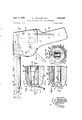
- FIG. 1 is a side, elevational view of the preferred embodiment of the wire winding device showing
- Fig. 2 is an enlarged, fragmentary, vertical, sectional'view of the forward portion of the winding device showing a portion of the terminal and the connector wire positionedtherein and showing the winding finger with the connector wire inserted therein;v
- Fig. 3 is a fragmentary, horizontal, sectional view taken on the line 3--3 of Fig. 2 and showing the winding finger therein in a position advanced or rotated; 90 with respect to the position shown in Fig. 2;
- Fig. 4 is a-detailed vertical cross-sectional view taken on the line 4--4-of Fig- 2;
- Fig. 5 is a plan, elevational, sectional view of the device taken on the line 5-5 of. Fig. 1 with parts broken away;
- Fig. 6 is a vertical, central, sectional view of a portion of the device with parts shown in elevation;
- Fig. 7 is a perspective view of the terminalv with the connector wire wound thereon
- Fig. 8- is a side, elevational view of a modified embodiment of the invention
- Fig. 9 is a fragmentary end elevational view of the device shown in Fig. 8;.
- Fig. 10 is an enlarged, plan view of the end portion of the winding device shown in Fig. 8 with parts thereof shown v in section and showing. the terminal and connector wire in position therein;
- Fig. 11 is a fragmentary, vertical, sectional viewtaken on the line HI l of Fig. 8 and showing the terminal and the connector wire in position therein;
- Fig. 12 is a plan, sectional view of the device taken on the line l2 --l2 of Fig. 8;
- Fig. 13' is a vertical, central, longitudinal, sectional view through the device
- Fig. 15 is an enlargedview in perspective of the end' of the winding finger.
- a fiat'type of terminal l5, as illustrated in Figs. 7 and 14 is frequently used and in order to make an electrical connection therewith, a. connector wire [6 is wound in spiral fashion tightly around the terminal for several convolutions, and the junction is enclosed. in solder to provide an. effective and protected electrical connection.
- the device is disclosed as a pistol type of winding tool comprising a housing 22 having a hand grip 24 extending downwardly therefrom.
- a housing 22 having a hand grip 24 extending downwardly therefrom.
- Secured in an aperture 26 (Fig. in a stationary boss 28 within the housing 22, as by means of a set screw 30, is one end of a stationary rod or shaft 32.
- the rod 32 extends outwardly through an aperture in the housing and is provided at its forward end with a rectangular recess 36 for receiving the end of the terminal I5 therein.
- a sleeve member 38 rotatably mounted on the stationary rod 32 is secured by means of a set screw 40 at its rear end in telescoping relation to a bushing M, which, in turn, is mounted for rotation on the rod 32 and within a bearing member 42 secured to the housing 22.
- the bushing 40 means of a pin 44 to a bevel gear 46, which is freely rotatable on the rod 32 and meshes with a bevel gear 48 having a cylindrical hub 50, which is rotatably mounted in a bearing aperture in the bearing member 42.
- a pinion gear 52 secured to the bevel gear 49 for rotation therewith, meshes with a gear sector 53 mounted for movement about a pivot pin 54 and having an operating or trigger lever 56 extending therefrom through an aperture in the housing 22.
- the sector 53 is stressed for rotation in a clockwise direction about its pivot 54, as viewed in Fig. 1, by a spring 51, the rotary movement of the sector in this direction being limited by a stop pin 58 engageable with the arm 56.
- the sleeve 38 is provided with a longitudinal and radially extending slot for receiving a winding finger 62.
- the winding finger 52 is pivotally mounted intermediate its ends on a pin 64 and has its forward end 65 positioned slightly beyond the end of the rod 32.
- a spring 66 engaging the rearwardly extending portion of the winding finger 62 stresses the finger for rotation about the pin 64 to urge the forward end 65 into engagement with the end of the rod 32.
- Extending longitudinally of the winding finger 62 from the forward end 65 thereof is a recess or aperture 68 for receiving the connector wire 16 therein.
- the bore 66 is formed in the winding finger as by drilling while the forward portion of the winding finger is straight, and after the bore 68 has been formed, the forward end 65 may be bent radially inwardly as shown in the drawings.
- portions of the forward end of the rod 32 are cut away forming pairs of oppositely disposed inclined surfaces '
- the inclined surfaces 19-10 and 12--12 in addition to providing clearance for is secured by the movement radially inwardly of the end 65 of the winding finger 62, form a cam track to guide the forward end 65 radially in and out, as the sleeve 38 and the winding finger 62 are rotated, to follow a rectangular path correspondmg generally to the rectangular cross-section of the terminal I5.
- the operator while holdmg the device in one hand inserts with the other hand the bared end of the connector wire I6 into the aperture 68 of the winding finger 62 as indicated in Fig. l and then moves the winding tool or device relative to the terminal to cause the end of the terminal to be positioned within the recess 36 of the stationary rod 32.
- the conductor wire I6 may then be bent downwardly, as indicated in Fig. 6, and held there while the operator engages and moves the lever 56 to actuate the driving mechanism and rotate the sleeve 38 and the Winding finger 62 through a predetermined number of revolutions, approximately three and one-half.
- the forward end 65 thereof will guide the bared end of the connector wire I6 about the terminal and, as successive convolutions are laid or wound on the terminal l5, they act to push the preceding convolutions longitudinally thereon so that, on completion of the winding operation, the end of the connector wire I6 will be Wound in a spiral form in tight engagement with the terminal and with the convolutions thereof in tight engagement with each other as shown in Fig. 7.
- the Wire winding device is shown as being of the manually operated pistol type tool comprising a housing having a han-- die or pistol grip 9
- a rod or shaft 84 secured in a recess in a member 86 (Fig. 12) formed as a part of the housing 80, extends outwardly from the housing and, at its forward end, is provided with a recess 88 for receiving one end of the terminal member I5, as illustrated in Figs. 10-13.
- a barrel or sleeve 90 is rotatably mounted on the shaft 84 and is provided, at one end, with an enlarged aperture for telescopingly receiving therein a bushing 9
- and the sleeve 90 respec-- tively, operatively connect the sleeve 90 for rotary movement with and for axial movement relative to the bushing 9
- has fixed thereto, as by being pressed therein, a bevel gear 95, which meshes with a bevel gear 96 mounted for rotation in a bearing member 98.
- the sector IOI has an operating arm I04 extending outwardly from the housing 80 and is stressed for rotation in a clockwise di rection, as viewed in Fig. 8, by a torsion spring I06, and a stop pin I01 serves to limit the rotation of the gear sector in this direction.
- Screw threads Ill! formed in the shaft 84 are engaged by the threaded end of a plug I I I (Fig. 12) secured to the sleeve 99 by a threaded member I I2 and serves to form a threaded connection between the rotatable sleeve 90 and the non-rotatable shaft 34.
- the drive Upon actuation of the operatmg arm I64, the drive is actuated to impart movement to the sleeve 99, causing it simultaneously to rotate through a predetermined number of revolutions and to move rearwardly on the shaft in a helical path.
- a coil spring II l interposed between the end of the bushing 9i and shoulder in the sleeve 90, serves to urge the sleeve longitudinally away from the bushing 52 and maintain the sleeve in its normal position, as indicated in Figs. 12 and 13.
- the sleeve 98 is provided with a radially and longitudinally extending slot for receiving a winding finger I I8 therein for r0- tation with the sleeve 98 and for pivotal movement about a pin no carried by the sleeve.
- a head I 26, formed on the forward end of the winding finger I I8, is positioned. axially beyond the end of the stationary shaft 8d and extends radially inwardly toward the axis of the shaft as into close relation with a terminal positioned in the recess 38 of the stationary shaft.
- a transversely extending groove I 22 is formed in the head IZQ for receiving the bared end of the connectar wire I6 therein and for guiding the connector wire I about the terminal I5.
- a spring iZd engaging the rearwardly extending portion of the winding finger I It, stresses the winding finger for rotation in a counter-clockwise direction about the pivot pin lit to urge the head I29 thereof into engagement with the terminal member I5.
- a stationary support and guide member I25 is positioned at the forward end of the shaft 84 and the sleeve 9
- the guide member I25 is formed on the forward end of the bracket I25 secured to a portion of the housing member 89, as illustrated in Figs. 8 and 9.
- the guide member I25 has an axially disposed central aperture to provide clearance for rotation and radial outward movement of the head of the winding finger I I8.
- a longitudinally extending slot IE8 is formed having an end wall engageable with the end of the connector wire It to locate the wir It in a predetermined position relative to the head I26 of the winding finger I It and to a terminal I5 positioned in the recess 85.
- a relatively wide recess I29 is formed to provide clearance for the reception of the free end of the i connector wire I5.
- the other end of the winding finger IIB is inclined to form a cam surface I 32, which coopcrates with an annular conical cam surface I3 l formed on a sleeve 35 mounted for reciprocable movement on the sleeve 5i).
- a ring I secured to the inner portion of the barrel I35 forms a shoulder for receiving the thrust of a coiled sprin I33 which reacts against the shoulder I39 on the sleeve 99 and serves to urge the sleeve I35 rearwardiy to its normal position where it engages a portion of the housing 38, as shown in Fig. 13.
- a lever use pivoted at its upper end I 32 to the sleeve E35 and fulcrumed intermediate its ends at I53 to the bracket 5%, has a finger piece I4 3; by means of which the lever may be actuated to impart forward axial movement to the sleeve I35 and cause the rocking of the winding finger H8 to a position permitting the application or insertion of the connector wire H6.
- the operator may then rock the actuat-' ing lever I68 to advance the sleeve I35 and rock the winding finger H8 to its open or inoperative position, with the head I20 thereof spaced from the terminal I5, after which the ashamed end of the connector wire I6 may be placed in front of the guide I20, aligned with the slot I28 therein and moved axially into engagement with the end thereof, after which the actuatin lever I40 may be released to permit the retraction of the sleeve I35 and the movement of the winding finger I I8 to its normal position.
- the head I23 of the winding finger I I8 moves radially inwardly, it engages the connector wire IS in the groove I22 thereof and urges it into firm engagement with the terminal I5.
- the upper portion of the conhector Wire I6 may be bent transversely and manually held in a fixed position on the supporting guide member I25, as indicated in Figs. 10 and 11. The operator may then engage and actuate the lever Illi which through the gear drive imparts rotation to the sleeve 953 through approximately three and one-half revolutions and simultaneously therewith causes an axial movement rearwardly of the sleeve relative to the stationary shaft and the terminal I5.
- the winding finger IIS moving therewith serves to wrap the iree end of the connector wire I6 spirally and tightly about the terminal I5 and with the convolutions thereof in spaced relation to each other as indicated in Fig. 14. Since the downwardly extending free end of the connector wire It, a portion of which is shown in Fig. 11, is longer than the radius of the central axial aperture through the guide member I26, the connector wire it is bent into a loop by the head I253 of the winding finger H8 as the winding finger II8 rotates to wind the Wire IE about the terminal I5, and the free end of the loop gets progressively shorter as the wire I5 passes through the groove I22 as it is progressively wound onto the terminal. On completion of the winding operation, the winding device may be withdrawn axially from the terminal IE and the connection formed thereon by the connector wire I6.
- a device for winding a connector wire about a fiat type terminal comprising a non-rotatable element having a recess in one end thereof for receiving oneend of a flat type terminal to position the terminal in predetermined relation longitudinally and transversely with respect to said element, a rotatable member mounted for rotation about said element, a winding finger pivotally mounted on said rotatable member for rotation therewith and having an end portion thereof adjacent the recess of said element, a recess in said end of the winding finger for receiving one end of a connector wire therein, means for rotating said rotarymember whereby said winding finger is caused to rotate and wind the connector wire positioned in the recess of said winding finger around the terminal positioned in the recess of said element, and means on the non-rotatable element operable in response to the rotation of said member for moving said end of the winding finger radially to maintain it in close proximity to the surfaces of the flat type terminal about which the connector wire is being wound.
- a device for winding a connector wire about a terminal comprising a rod having a recess at one end thereof for receiving one end of a flat type terminal therein to position the terminal in predetermined relation to said rod, a sleeve mounted for rotation on said rod, a longitudinally extending winding finger pivotally mounted intermediate its ends on said sleeve for rotation therewith and having an end portion thereof adjacent the recess of said rod, cam surfaces on the end of said rod forming a cam track conforming generally to the cross-section of said terminal, spring means on said sleeve stressing said winding finger to urge said one end thereof into engagement with said cam track, a longitudinally disposed recess in said winding finger extending inwardly from said one end, means for supporting said rod, and drive means mounted on said supporting means for rotating said sleeve whereby said winding finger is caused to rotate and wind an end portion of a connector wire positioned in the recess of said winding finger around a terminal positioned in the recess of said rod.
- a winding tool for winding a connector wire about a terminal comprising the combination of a non-rotatable element having a recess in one end thereof for receiving one end of a terminal therein for holding the terminal against lateral movement, said element having means engageable with the end of the terminal to limit the movement of said terminal longitudinally of said element to a predetermined position, a winding member having an end thereof disposed adjacent the recess in said non-rotatable element and a terminal positioned therein and having a recess for slidably receiving a portion of a connector wire therein and supporting said connector wire in engagement with said terminal, rotatable means mounted on said non-rotatable element for supporting said winding member for rotation about said non-rotatable element and for transverse movement relative thereto, means on said rotatable means for stressing said winding member for movement to cause the end thereof to move inwardly toward the axis of rotation to maintain the connector wire in engagement with the terminal, and drive means operatively connected to said winding member for imparting rotation
- a tool for winding a connector wire about a terminal comprising a non-rotatable element having a recess for receiving one end of a terminal therein to position the terminal in predetermined relation to said element, a rotatable member mounted for rotation about said element, means interconnecting said rotatable member and said element for effecting a relative axial movement therebetween in response to rotation of said rotatable member, a winding finger having an end thereof positioned adjacent the recess, means mounting said winding finger for rotary and axial movement with said rotatable member and for transverse movement relative thereto, spring means on said rotatable member and cooperating with said winding finger urging said end thereof radially inwardly toward the axis of rotation and a terminal positioned in said recess, a guide recess in the end of said winding finger for receiving an end portion of a connector wire therein to guide the connector Wire around the terminal, and drive means for rotating said rotatable member whereby said winding finger is caused to move in a
- a device for winding a connector wire about a terminal comprising a non-rotatable rod having a recess in one end thereof for receiving one end of the terminal to position the terminal in predetermined relation to said rod, means for supporting said rod, a sleeve mounted for rotation about said rod, a longitudinally extending winding finger pivotally mounted on said sleeve for rotation therewith and having an end portion thereof positioned beyond the end of said rod and extending inwardly toward the axis of rotation of said sleeve, said end having a transverse recess therein for receiving a connector wire, spring means on said sleeve stressing said winding finger to urge said end thereof toward the axis of rotation of said sleeve for holding a wire positioned in the groove of said end transversely against a terminal positioned in the recess in said rod, a member mounted on said supporting means and positioned adjacent said one end of the winding finger for supporting a portion of the connector wire during the winding operation, and drive means on said
- a winding tool for winding a connector wire about a fiat type terminal comprising a nonrotatable rod having a recess at one end thereof for receiving one end of a terminal therein to position the terminal in predetermined relation to said rod, supporting means including a handle for supporting said rod, a sleeve mounted for rotation about said rod, a longitudinally extending winding finger pivotally mounted intermediate its ends on said sleeve for rotation therewith and having an end portion thereof extending beyond the end of said rod and inwardly toward the axis of rotation of said sleeve, spring means on said sleeve stressing said winding finger to urge said one end toward the axis of rotation of said sleeve, said one end of the winding finger having a transverse recess for receiving a con nector wire therein to position the connector wire transversely against a terminal positioned in the recess of said rod, a guide member mounted on said supporting means and positioned adiacent said one end of the winding finger to guide
- a winding tool for winding a connector wire about a terminal comprising a non-rotatable rod having a recess in one end thereof for receiving one end of a terminal therein to position the terminal in predetermined relation to said rod, means for supporting said rod, a sleeve mounted for rotation on said rod, threaded means interconnecting said rod and said sleeve for imparting axial movement to said sleeve in response to rotation thereof, a longitudinally extending windin finger pivotally mounted on said sleeve for rotary movement therewith and having one end thereof extending beyond the end of said rod and inwardly toward the axis of rotation of said sleeve, said one end of the winding finger having a transversely extending recess for receiving a connector wire therein, spring means on said sleeve stressing said winding finger to urge said one end thereof toward the axis of rotation of said sleeve for holding a wire positioned in the transverse groove of said one end against a terminal positioned
- a winding tool for winding a connector wire about a terminal comprising a non-rotatable rod having a recess in one end thereof for receiving one end of a terminal therein to position the terminal in predetermined relation to said rod, supporting means for supporting said rod, a sleeve mounted for rotation on said rod, threaded means interconnecting said rod and said sleeve for imparting axial movement to said sleeve in response to rotation thereof, means limiting the axial movement of said sleeve, spring means urging said sleeve for axial movement in one direction, a longitudinally extending winding finger pivotally mounted on said sleeve for rotary movement therewith and having one end thereof extending beyond the end of said rod and inwardly toward the axis of rotation of said sleeve, said one end of the winding finger having a transversely extending recess for receiving a connector wire therein, sprin means on said sleeve stressing said Winding finger to urge said one end thereof
- a hand tool for winding a connector wire about a fiat type terminal comprising a handle member, a non-rotatable element supported by said handle member and having a rectangular recess in one end thereof for receiving one end of a terminal therein to position the terminal longitudinally and laterally in a predetermined relation relative to said element, a rotary member mounted for rotation on said element, a winding finger pivotaliy connected on said rotary member for rotation therewith and for rocking movement relative thereto and transversely thereof, said finger having its forward end extending forwardly beyond the end of said element and having a bore extending longitudinally thereof from the front end for receiving a predetermined length of the end portion of a connector wire, said finger having its forward end directed inwardly toward the axis to lay the wire as it leaves the finger onto the terminal, resilient means on said rotary member for stressing said finger for movement in one direction to urge the forward end thereof inwardly toward the axis of rotation and the terminal in said recess, and cam surfaces on said element conforming substantially to the rectangular cross-
- a hand tool for winding a connector wire about a flat type terminal comprising a handle member, a non-rotatable shaft supported by said handle member and having a rectangular recess at one end thereof for receiving one end of a terminal therein to position the terminal longitudinally and laterally in a predetermined relation with respect to said shaft, a tubular member mounted for rotation on said shaft and having its forward end extending beyond the end of said shaft and having conical surfaces for guiding a terminal toward the recess in the end of said shaft, a winding finger pivotally connectedintermediate its ends on said tubular member for rotation therewith and for oscillatable movement transversely thereof, said finger having its forward end extending forwardly beyond the end of said shaft and having a bore extending longitudinally thereof from the front end for receiving a predetermined length of the end portion of a connector wire, said finger having its forward end directed inwardly toward the axis to lay the wire as it leaves the finger onto the terminal, spring means on said tubular member stressing said finger for movement to urge the forward end thereof in
- device for winding a connector wire about a terminal comprising a non-rotatable element having a recess in one end thereof for receiving one end of a terminal therein to hold the terminal against lateral movement, means on said element engageable with the end of the terminal to limit the movement thereof longitudinally of said element to a predetermined position, a member mounted for rotation about said element, a winding finger pivotally mounted on said rotatable member for rotation therewith and having an end portion thereof adjacent the recess of said element, said winding finger having a recess in the end thereof for receiving a connector wire, means mounted on said device to stress said winding finger to urge said end thereof toward the element and to urge the connector wire in the recess thereof into engagement with a terminal positioned in the recess of said element, and means for rotating said rotary member whereby said winding finger is caused to rotate and wind the connector wire positioned in the recess of said winding finger around the terminal positioned in the recess of said element and to thereby efiect relative movement longitudinally
- a device for Winding a connector wire about a fiat-type terminal comprising a non-rotatable rod having a recess in one end thereof for receiving one end of a terminal therein for supporting the terminal against lateral movement, said rod having means engageable with the end of the terminal to limit the movement thereof longitudinally of said rod to a predetermined position, a sleeve mounted for rotation on said rod, a longitudinally extending Winding finger pivotally mounted on said sleeve for rotation therewith and having an end portion adjacent the recess of said rod, said one end of the winding finger having a longitudinally extending recess therein for receiving a connector wire, means mounted on said sleeve stressing said winding finger to urge said one end thereof toward the rod to urge the connector wire in the recess thereof into engagement with a terminal positioned in the recess of said rod, and means for rotating said sleeve whereby said winding finger is caused to rotate and wind a connector wire positioned in the recess of said winding finger around
- a device for winding a connector wire about a terminal comprising a non-rotatable element having a recess in one end thereof for receiving one end of the terminal therein for holding the terminal against lateral movement, said element having means engageable with the end of the terminal to limit the movement thereof longitudinally of said element to a predetermined position, a member mounted for rotation about said element, a winding finger having an end thereof positioned adjacent the recess, means mounting said winding finger on said rotatable member for rotation therewith and for transverse movement relative to said rotatable member, means on said rotatable member cooperatin with said winding finger to urge said end thereof radially inwardly toward the axis of rotation and toward a terminal positioned in said recess to press the connector wire against the terminal, a recess in the end of said winding finger for receiving an end portion of a connector wire therein to guide the connector wire around the terminal, and drive means for rotating said rotatable member whereby said winding finger is caused to rotate and wind a portion of
Landscapes
- Engineering & Computer Science (AREA)
- Manufacturing & Machinery (AREA)
- Manufacturing Of Electrical Connectors (AREA)
Description
Aug. 11, 1953 E. J. BEAULIEU ET AL DEVICE FOR WINDING WIRE ABOUT TERMINALS 4 Sheets-Sheet 1 Filed May 6, 1949 ES Y NR 5 L mug m MAA m MBA T w x H a ah Aug. 11, 1953 E. J. BEAULIEU ETAL DEVICE FOR WINDING WIRE ABOUT TERMINALS 4 Sheets-Sheet 2 Filed May 6, 1949 l/VVE/VTORS F. J. BFAUL/EU A .5 HA A 6AISN w Aug. 11, 1953 E. J. BEAULIEU ETAL DEVICE FOR WINDING WIRE ABOUT TERMINALS Filed May 6, 1949 4 Sheets-Sheet 5 ILIIJI I! 1 QW an I INVf/VTO/FS' t. J BEA 04 /1/ L. 5. HA AGE/V3511! I i! I 0. SCHA RER ATTORNEY ow m mm\ on E. .1. BEAULIEU ETAL 2,648,356
DEVICE FOR WINDING WIRE ABOUT TERMINALS 4 Sheets-Sheet 4 Aug. 11, 1953 Filed May 6, 1949 wm mm .qw m: N\ u g m3 9 $2 m:
Patented Aug. 11, 1953 DEVICE FOR WINDING WIRE ABOUT TERMINALS Ezra J. Beaulieu, Downers Grove, Leif E. Haagen-- sen, Barrington, and Oscarv Scharer, Chicago, Ill., assignors to Western Electric Company, Incorporated, New York, N. Y a corporation of New York Application May 6, 1949, Serial No. 91,748
13 Qlaims.
control of the operator and slotted at its forward.
end for receiving a pivoted axially extending winding finger for rotation therewith. The
winding finger apertured longitudinally from its 7' forwardend to receive the connector wire therein is positioned with its forward end adjacent the recess in the stationary shaft and is pivotally mounted in the rotatable sleeve and stressed for movement so as to urge the forward end of the winding finger and the connector wire therein into close proximity with the terminal member inserted in the recess of the device whereby as the sleeve is rotated the winding finger serves to wind the connector wire spirally about the terminal.
In another embodiment of the invention the wire winding device is provided with a stationary rod having a terminal receiving recess at its forward end having a sleeve mounted thereon for rotation under control of the operator. Pivotally mounted in a slot in the forward end of the sleeve is a winding finger which has a head at the forward end thereof extending beyond the recessed end of the stationary rod and having a transverse recess for receiving a connector wire therein. A slotted stationary guide at the forward end of the rotatable sleeve serves to support the connector wire in position adjacent the terminal, and a helical threaded connection is provided between the stationary rod on the rotatable sleeve to retract the sleeve on the rod during the rotation thereof so that during the rotation of the sleeve, the head of the springpressed winding finger yieldably urges the connector wire against the terminal and winds the free end thereof into a helix about the terminal and in tightly Wrapped engagement therewith.
Other objects and advantages will be apparent by reference to the following detailed description of the invention and the accompanying drawings illustrating several embodiments thereof, in which Fig. 1 is a side, elevational view of the preferred embodiment of the wire winding device showing,
in dot. and dash lines, a connector wire inserted in the winding finger thereof and. a terminal to which the connector wire is to be secured;
Fig. 2 is an enlarged, fragmentary, vertical, sectional'view of the forward portion of the winding device showing a portion of the terminal and the connector wire positionedtherein and showing the winding finger with the connector wire inserted therein;v
Fig. 3 is a fragmentary, horizontal, sectional view taken on the line 3--3 of Fig. 2 and showing the winding finger therein in a position advanced or rotated; 90 with respect to the position shown in Fig. 2;
Fig. 4 is a-detailed vertical cross-sectional view taken on the line 4--4-of Fig- 2;
Fig. 5 is a plan, elevational, sectional view of the device taken on the line 5-5 of. Fig. 1 with parts broken away;
Fig. 6 is a vertical, central, sectional view of a portion of the device with parts shown in elevation;
Fig. 7 is a perspective view of the terminalv with the connector wire wound thereon Fig. 8-is a side, elevational view of a modified embodiment of the invention;
Fig. 9 is a fragmentary end elevational view of the device shown in Fig. 8;.
Fig. 10 is an enlarged, plan view of the end portion of the winding device shown in Fig. 8 with parts thereof shown v in section and showing. the terminal and connector wire in position therein;
Fig. 11 is a fragmentary, vertical, sectional viewtaken on the line HI l of Fig. 8 and showing the terminal and the connector wire in position therein;
Fig. 12 is a plan, sectional view of the device taken on the line l2 --l2 of Fig. 8;
Fig. 13' is a vertical, central, longitudinal, sectional view through the device;
Fig. 14 is=a perspective view of the terminal with.
the connector wire wound. thereon; and
Fig. 15 is an enlargedview in perspective of the end' of the winding finger.
In the manufacture of electrical apparatus such as is used, for example, in the telephone and radio art, a fiat'type of terminal l5, as illustrated in Figs. 7 and 14, is frequently used and in order to make an electrical connection therewith, a. connector wire [6 is wound in spiral fashion tightly around the terminal for several convolutions, and the junction is enclosed. in solder to provide an. effective and protected electrical connection.
' The winding of'the c'onnectorwire [6 about the terminal I5, which heretofore has mainly been a manual operation, may be greatly facilitated by the use of portable wire winding devices of the type herein disclosed.
Referring now to the embodiment of the invention disclosed in Figs. 1 to 6, the device is disclosed as a pistol type of winding tool comprising a housing 22 having a hand grip 24 extending downwardly therefrom. Secured in an aperture 26 (Fig. in a stationary boss 28 within the housing 22, as by means of a set screw 30, is one end of a stationary rod or shaft 32. The rod 32 extends outwardly through an aperture in the housing and is provided at its forward end with a rectangular recess 36 for receiving the end of the terminal I5 therein. A sleeve member 38 rotatably mounted on the stationary rod 32 is secured by means of a set screw 40 at its rear end in telescoping relation to a bushing M, which, in turn, is mounted for rotation on the rod 32 and within a bearing member 42 secured to the housing 22.
At its rear end, the bushing 40 means of a pin 44 to a bevel gear 46, which is freely rotatable on the rod 32 and meshes with a bevel gear 48 having a cylindrical hub 50, which is rotatably mounted in a bearing aperture in the bearing member 42. A pinion gear 52, secured to the bevel gear 49 for rotation therewith, meshes with a gear sector 53 mounted for movement about a pivot pin 54 and having an operating or trigger lever 56 extending therefrom through an aperture in the housing 22. The sector 53 is stressed for rotation in a clockwise direction about its pivot 54, as viewed in Fig. 1, by a spring 51, the rotary movement of the sector in this direction being limited by a stop pin 58 engageable with the arm 56. It will be apparent, from the description thus far, that, upon engagement and actuation of the lever 56 in a counter-clockwise direction, the sleeve 38 will be caused to rotate through a predetermined number of revolutions, and, upon disengagement of the lever 56, the spring 51 will serve to rotate the sleeve 38 in the opposite direction and restore it to its normal position, as indicated in Figs. 5 and 6 of the drawings.
At its forward end the sleeve 38 is provided with a longitudinal and radially extending slot for receiving a winding finger 62. The winding finger 52 is pivotally mounted intermediate its ends on a pin 64 and has its forward end 65 positioned slightly beyond the end of the rod 32. A spring 66 engaging the rearwardly extending portion of the winding finger 62 stresses the finger for rotation about the pin 64 to urge the forward end 65 into engagement with the end of the rod 32. Extending longitudinally of the winding finger 62 from the forward end 65 thereof is a recess or aperture 68 for receiving the connector wire 16 therein. The bore 66 is formed in the winding finger as by drilling while the forward portion of the winding finger is straight, and after the bore 68 has been formed, the forward end 65 may be bent radially inwardly as shown in the drawings.
To enable the end 65 of the winding finger 62 to move into close proximity to a terminal member I5 positioned in the recess 35 of the rod 32, portions of the forward end of the rod 32 are cut away forming pairs of oppositely disposed inclined surfaces '|0-10 and I2-'|2 arranged in rectangular formation about the rectangular recess 36. The inclined surfaces 19-10 and 12--12, in addition to providing clearance for is secured by the movement radially inwardly of the end 65 of the winding finger 62, form a cam track to guide the forward end 65 radially in and out, as the sleeve 38 and the winding finger 62 are rotated, to follow a rectangular path correspondmg generally to the rectangular cross-section of the terminal I5.
' In using this device the operator while holdmg the device in one hand inserts with the other hand the bared end of the connector wire I6 into the aperture 68 of the winding finger 62 as indicated in Fig. l and then moves the winding tool or device relative to the terminal to cause the end of the terminal to be positioned within the recess 36 of the stationary rod 32. The conductor wire I6 may then be bent downwardly, as indicated in Fig. 6, and held there while the operator engages and moves the lever 56 to actuate the driving mechanism and rotate the sleeve 38 and the Winding finger 62 through a predetermined number of revolutions, approximately three and one-half. As the winding finger 62 is revolved about the rod 32, the forward end 65 thereof will guide the bared end of the connector wire I6 about the terminal and, as successive convolutions are laid or wound on the terminal l5, they act to push the preceding convolutions longitudinally thereon so that, on completion of the winding operation, the end of the connector wire I6 will be Wound in a spiral form in tight engagement with the terminal and with the convolutions thereof in tight engagement with each other as shown in Fig. 7.
In the embodiment of the invention illustrated in Figs. 8 to 13, the Wire winding device is shown as being of the manually operated pistol type tool comprising a housing having a han-- die or pistol grip 9|. A rod or shaft 84, secured in a recess in a member 86 (Fig. 12) formed as a part of the housing 80, extends outwardly from the housing and, at its forward end, is provided with a recess 88 for receiving one end of the terminal member I5, as illustrated in Figs. 10-13. A barrel or sleeve 90 is rotatably mounted on the shaft 84 and is provided, at one end, with an enlarged aperture for telescopingly receiving therein a bushing 9|. Pins 92-92, fitting in apertures 93, and longitudinally extending slots 94 in the bushing 9| and the sleeve 90, respec-- tively, operatively connect the sleeve 90 for rotary movement with and for axial movement relative to the bushing 9|. The bushing 9| has fixed thereto, as by being pressed therein, a bevel gear 95, which meshes with a bevel gear 96 mounted for rotation in a bearing member 98. Fixed to the bevel gear 96 for rotation therewith 1s a gear I00, which meshes with a gear sector IOI mounted for oscillating movement about a pivot pin I02. The sector IOI has an operating arm I04 extending outwardly from the housing 80 and is stressed for rotation in a clockwise di rection, as viewed in Fig. 8, by a torsion spring I06, and a stop pin I01 serves to limit the rotation of the gear sector in this direction.
Screw threads Ill! formed in the shaft 84 are engaged by the threaded end of a plug I I I (Fig. 12) secured to the sleeve 99 by a threaded member I I2 and serves to form a threaded connection between the rotatable sleeve 90 and the non-rotatable shaft 34. Upon actuation of the operatmg arm I64, the drive is actuated to impart movement to the sleeve 99, causing it simultaneously to rotate through a predetermined number of revolutions and to move rearwardly on the shaft in a helical path. Upon release of the operating arm its, the torsion spr n I 6 a s, throu h the drive, to restore the sleeve to its normal position. A coil spring II l, interposed between the end of the bushing 9i and shoulder in the sleeve 90, serves to urge the sleeve longitudinally away from the bushing 52 and maintain the sleeve in its normal position, as indicated in Figs. 12 and 13.
At its forward end, the sleeve 98 is provided with a radially and longitudinally extending slot for receiving a winding finger I I8 therein for r0- tation with the sleeve 98 and for pivotal movement about a pin no carried by the sleeve. A head I 26, formed on the forward end of the winding finger I I8, is positioned. axially beyond the end of the stationary shaft 8d and extends radially inwardly toward the axis of the shaft as into close relation with a terminal positioned in the recess 38 of the stationary shaft. A transversely extending groove I 22 is formed in the head IZQ for receiving the bared end of the connectar wire I6 therein and for guiding the connector wire I about the terminal I5. A spring iZd, engaging the rearwardly extending portion of the winding finger I It, stresses the winding finger for rotation in a counter-clockwise direction about the pivot pin lit to urge the head I29 thereof into engagement with the terminal member I5.
In order to align the connector wire It with the groove I22 in the winding finger IE8 and to support it during rotation of the winding finger, a stationary support and guide member I25 is positioned at the forward end of the shaft 84 and the sleeve 9 The guide member I25 is formed on the forward end of the bracket I25 secured to a portion of the housing member 89, as illustrated in Figs. 8 and 9. The guide member I25 has an axially disposed central aperture to provide clearance for rotation and radial outward movement of the head of the winding finger I I8. In the upper wall of the member i25, a longitudinally extending slot IE8 is formed having an end wall engageable with the end of the connector wire It to locate the wir It in a predetermined position relative to the head I26 of the winding finger I It and to a terminal I5 positioned in the recess 85. In the lower right-hand portion of the guide I25, as viewed from the front (Fig. 11) a relatively wide recess I29 is formed to provide clearance for the reception of the free end of the i connector wire I5. When located in the end of the slot I28, as indicated in 10 and 11, the connector wire It is positioned adjacent the teriinal E 5 about which the connector wire is to be wound in alignment with the groove I22 in i the head I26 of the winding finger H8.
The other end of the winding finger IIB is inclined to form a cam surface I 32, which coopcrates with an annular conical cam surface I3 l formed on a sleeve 35 mounted for reciprocable movement on the sleeve 5i). A ring I secured to the inner portion of the barrel I35 forms a shoulder for receiving the thrust of a coiled sprin I33 which reacts against the shoulder I39 on the sleeve 99 and serves to urge the sleeve I35 rearwardiy to its normal position where it engages a portion of the housing 38, as shown in Fig. 13. A lever use, pivoted at its upper end I 32 to the sleeve E35 and fulcrumed intermediate its ends at I53 to the bracket 5%, has a finger piece I4 3; by means of which the lever may be actuated to impart forward axial movement to the sleeve I35 and cause the rocking of the winding finger H8 to a position permitting the application or insertion of the connector wire H6.
. nal in the recess 88 of the non-rotatable shaft 84 as illustrated in Figs. 12 and 13. With the index finger, the operator may then rock the actuat-' ing lever I68 to advance the sleeve I35 and rock the winding finger H8 to its open or inoperative position, with the head I20 thereof spaced from the terminal I5, after which the hatred end of the connector wire I6 may be placed in front of the guide I20, aligned with the slot I28 therein and moved axially into engagement with the end thereof, after which the actuatin lever I40 may be released to permit the retraction of the sleeve I35 and the movement of the winding finger I I8 to its normal position. As the head I23 of the winding finger I I8 moves radially inwardly, it engages the connector wire IS in the groove I22 thereof and urges it into firm engagement with the terminal I5. The upper portion of the conhector Wire I6 may be bent transversely and manually held in a fixed position on the supporting guide member I25, as indicated in Figs. 10 and 11. The operator may then engage and actuate the lever Illi which through the gear drive imparts rotation to the sleeve 953 through approximately three and one-half revolutions and simultaneously therewith causes an axial movement rearwardly of the sleeve relative to the stationary shaft and the terminal I5. During this rotary and axial movement of the sleeve, the winding finger IIS moving therewith serves to wrap the iree end of the connector wire I6 spirally and tightly about the terminal I5 and with the convolutions thereof in spaced relation to each other as indicated in Fig. 14. Since the downwardly extending free end of the connector wire It, a portion of which is shown in Fig. 11, is longer than the radius of the central axial aperture through the guide member I26, the connector wire it is bent into a loop by the head I253 of the winding finger H8 as the winding finger II8 rotates to wind the Wire IE about the terminal I5, and the free end of the loop gets progressively shorter as the wire I5 passes through the groove I22 as it is progressively wound onto the terminal. On completion of the winding operation, the winding device may be withdrawn axially from the terminal IE and the connection formed thereon by the connector wire I6.
It is to be understood that the above-described arrangements are simply illustrative of the application of the principles of the invention. Numerous other arrangements may be readily devised by those skilled in the art which will embody the principles of the invention and fallwithin the spirit and scope thereof.
What is claimed is:
1. A device for winding a connector wire about a fiat type terminal comprising a non-rotatable element having a recess in one end thereof for receiving oneend of a flat type terminal to position the terminal in predetermined relation longitudinally and transversely with respect to said element, a rotatable member mounted for rotation about said element, a winding finger pivotally mounted on said rotatable member for rotation therewith and having an end portion thereof adjacent the recess of said element, a recess in said end of the winding finger for receiving one end of a connector wire therein, means for rotating said rotarymember whereby said winding finger is caused to rotate and wind the connector wire positioned in the recess of said winding finger around the terminal positioned in the recess of said element, and means on the non-rotatable element operable in response to the rotation of said member for moving said end of the winding finger radially to maintain it in close proximity to the surfaces of the flat type terminal about which the connector wire is being wound.
2. A device for winding a connector wire about a terminal comprising a rod having a recess at one end thereof for receiving one end of a flat type terminal therein to position the terminal in predetermined relation to said rod, a sleeve mounted for rotation on said rod, a longitudinally extending winding finger pivotally mounted intermediate its ends on said sleeve for rotation therewith and having an end portion thereof adjacent the recess of said rod, cam surfaces on the end of said rod forming a cam track conforming generally to the cross-section of said terminal, spring means on said sleeve stressing said winding finger to urge said one end thereof into engagement with said cam track, a longitudinally disposed recess in said winding finger extending inwardly from said one end, means for supporting said rod, and drive means mounted on said supporting means for rotating said sleeve whereby said winding finger is caused to rotate and wind an end portion of a connector wire positioned in the recess of said winding finger around a terminal positioned in the recess of said rod.
3. A winding tool for winding a connector wire about a terminal comprising the combination of a non-rotatable element having a recess in one end thereof for receiving one end of a terminal therein for holding the terminal against lateral movement, said element having means engageable with the end of the terminal to limit the movement of said terminal longitudinally of said element to a predetermined position, a winding member having an end thereof disposed adjacent the recess in said non-rotatable element and a terminal positioned therein and having a recess for slidably receiving a portion of a connector wire therein and supporting said connector wire in engagement with said terminal, rotatable means mounted on said non-rotatable element for supporting said winding member for rotation about said non-rotatable element and for transverse movement relative thereto, means on said rotatable means for stressing said winding member for movement to cause the end thereof to move inwardly toward the axis of rotation to maintain the connector wire in engagement with the terminal, and drive means operatively connected to said winding member for imparting rotation thereto to wind a connector wire positioned in the recess in said winding member about a terminal positioned in the recess in said element.
4. A tool for winding a connector wire about a terminal comprising a non-rotatable element having a recess for receiving one end of a terminal therein to position the terminal in predetermined relation to said element, a rotatable member mounted for rotation about said element, means interconnecting said rotatable member and said element for effecting a relative axial movement therebetween in response to rotation of said rotatable member, a winding finger having an end thereof positioned adjacent the recess, means mounting said winding finger for rotary and axial movement with said rotatable member and for transverse movement relative thereto, spring means on said rotatable member and cooperating with said winding finger urging said end thereof radially inwardly toward the axis of rotation and a terminal positioned in said recess, a guide recess in the end of said winding finger for receiving an end portion of a connector wire therein to guide the connector Wire around the terminal, and drive means for rotating said rotatable member whereby said winding finger is caused to move in a helical path and wind a portion of the connector wire positioned in the guide recess of said winding finger around the terminal positioned in the recess of said element.
5. A device for winding a connector wire about a terminal comprising a non-rotatable rod having a recess in one end thereof for receiving one end of the terminal to position the terminal in predetermined relation to said rod, means for supporting said rod, a sleeve mounted for rotation about said rod, a longitudinally extending winding finger pivotally mounted on said sleeve for rotation therewith and having an end portion thereof positioned beyond the end of said rod and extending inwardly toward the axis of rotation of said sleeve, said end having a transverse recess therein for receiving a connector wire, spring means on said sleeve stressing said winding finger to urge said end thereof toward the axis of rotation of said sleeve for holding a wire positioned in the groove of said end transversely against a terminal positioned in the recess in said rod, a member mounted on said supporting means and positioned adjacent said one end of the winding finger for supporting a portion of the connector wire during the winding operation, and drive means on said supporting means for rotating said sleeve whereby said winding finger is caused to rotate and wind a connector wire positioned in the recess of said winding finger around a terminal positioned in the recess of said rod.
6. A winding tool for winding a connector wire about a fiat type terminal comprising a nonrotatable rod having a recess at one end thereof for receiving one end of a terminal therein to position the terminal in predetermined relation to said rod, supporting means including a handle for supporting said rod, a sleeve mounted for rotation about said rod, a longitudinally extending winding finger pivotally mounted intermediate its ends on said sleeve for rotation therewith and having an end portion thereof extending beyond the end of said rod and inwardly toward the axis of rotation of said sleeve, spring means on said sleeve stressing said winding finger to urge said one end toward the axis of rotation of said sleeve, said one end of the winding finger having a transverse recess for receiving a con nector wire therein to position the connector wire transversely against a terminal positioned in the recess of said rod, a guide member mounted on said supporting means and positioned adiacent said one end of the winding finger to guide a connector wire into position to be engaged by said end of the winding and for holding a portion of said connector wire against movement during the winding operation, an annular member mounted for sliding movement on said sleeve and having a cam surface engageable with the other end of said winding finger to rock said winding finger against said spring means in response to an axial movement of said annular member, means mounted on said supporting means operable to impart axial movement to said annular member, and drive means on said supporting means for rotating said sleeve whereby said winding finger is caused to rotate and wind a connector wire positioned in the recess of said winding finger around a terminal positioned in the recess of said rod.
7. A winding tool for winding a connector wire about a terminal comprising a non-rotatable rod having a recess in one end thereof for receiving one end of a terminal therein to position the terminal in predetermined relation to said rod, means for supporting said rod, a sleeve mounted for rotation on said rod, threaded means interconnecting said rod and said sleeve for imparting axial movement to said sleeve in response to rotation thereof, a longitudinally extending windin finger pivotally mounted on said sleeve for rotary movement therewith and having one end thereof extending beyond the end of said rod and inwardly toward the axis of rotation of said sleeve, said one end of the winding finger having a transversely extending recess for receiving a connector wire therein, spring means on said sleeve stressing said winding finger to urge said one end thereof toward the axis of rotation of said sleeve for holding a wire positioned in the transverse groove of said one end against a terminal positionedin the recess of said rod, a guide member mounted on said supporting means and positioned adjacent said one end of the winding finger for guiding a connector wire into position to be engaged by said one end of the winding member and for holding a portion of said connector wire against rotation during the winding operation, and drive means mounted on said supporting means for rotating said sleeve through a predetermined number of revolutions whereby said winding finger is caused to rotate and wind a connector wire positioned in the recess of said winding finger around a terminal positioned in the recess of said rod.
8. A winding tool for winding a connector wire about a terminal comprising a non-rotatable rod having a recess in one end thereof for receiving one end of a terminal therein to position the terminal in predetermined relation to said rod, supporting means for supporting said rod, a sleeve mounted for rotation on said rod, threaded means interconnecting said rod and said sleeve for imparting axial movement to said sleeve in response to rotation thereof, means limiting the axial movement of said sleeve, spring means urging said sleeve for axial movement in one direction, a longitudinally extending winding finger pivotally mounted on said sleeve for rotary movement therewith and having one end thereof extending beyond the end of said rod and inwardly toward the axis of rotation of said sleeve, said one end of the winding finger having a transversely extending recess for receiving a connector wire therein, sprin means on said sleeve stressing said Winding finger to urge said one end thereof toward the axis of rotation of said sleeve for holding a wire positioned in the transverse groove of said one end against a terminal positioned in the recess of said rod, a guide member mounted on said supporting means and positioned adjacent said one end of the winding finger for guiding a connector wire into position to be engaged by said one end of the winding member and for holding a portion of said connector wire against rotation during the winding operation, and drive means mounted on said supporting means for rotating said sleeve through a predetermined i0 number of revolutions whereby said winding finger is caused to rotate and wind a connector wire positioned in the recess of said winding finger around a terminal positioned in the recess of said rod.
9. A hand tool for winding a connector wire about a fiat type terminal comprising a handle member, a non-rotatable element supported by said handle member and having a rectangular recess in one end thereof for receiving one end of a terminal therein to position the terminal longitudinally and laterally in a predetermined relation relative to said element, a rotary member mounted for rotation on said element, a winding finger pivotaliy connected on said rotary member for rotation therewith and for rocking movement relative thereto and transversely thereof, said finger having its forward end extending forwardly beyond the end of said element and having a bore extending longitudinally thereof from the front end for receiving a predetermined length of the end portion of a connector wire, said finger having its forward end directed inwardly toward the axis to lay the wire as it leaves the finger onto the terminal, resilient means on said rotary member for stressing said finger for movement in one direction to urge the forward end thereof inwardly toward the axis of rotation and the terminal in said recess, and cam surfaces on said element conforming substantially to the rectangular cross-section of said terminal for limiting the inward movement of said winding finger to a predetermined position of close proximity to said terminal.
10. A hand tool for winding a connector wire about a flat type terminal comprising a handle member, a non-rotatable shaft supported by said handle member and having a rectangular recess at one end thereof for receiving one end of a terminal therein to position the terminal longitudinally and laterally in a predetermined relation with respect to said shaft, a tubular member mounted for rotation on said shaft and having its forward end extending beyond the end of said shaft and having conical surfaces for guiding a terminal toward the recess in the end of said shaft, a winding finger pivotally connectedintermediate its ends on said tubular member for rotation therewith and for oscillatable movement transversely thereof, said finger having its forward end extending forwardly beyond the end of said shaft and having a bore extending longitudinally thereof from the front end for receiving a predetermined length of the end portion of a connector wire, said finger having its forward end directed inwardly toward the axis to lay the wire as it leaves the finger onto the terminal, spring means on said tubular member stressing said finger for movement to urge the forward end thereof inwardly toward the axis of rotation and the terminal in said recess, and cam surfaces on said element conforming substantially to the rectangular cross-section of said terminal for limiting the inward movement of said winding finger to a predetermined position of close proximity to said terminal.
11. device for winding a connector wire about a terminal comprising a non-rotatable element having a recess in one end thereof for receiving one end of a terminal therein to hold the terminal against lateral movement, means on said element engageable with the end of the terminal to limit the movement thereof longitudinally of said element to a predetermined position, a member mounted for rotation about said element, a winding finger pivotally mounted on said rotatable member for rotation therewith and having an end portion thereof adjacent the recess of said element, said winding finger having a recess in the end thereof for receiving a connector wire, means mounted on said device to stress said winding finger to urge said end thereof toward the element and to urge the connector wire in the recess thereof into engagement with a terminal positioned in the recess of said element, and means for rotating said rotary member whereby said winding finger is caused to rotate and wind the connector wire positioned in the recess of said winding finger around the terminal positioned in the recess of said element and to thereby efiect relative movement longitudinally between the terminal and the non-rotatable element as said connector wire is wound around said terminal.
12. A device for Winding a connector wire about a fiat-type terminal comprising a non-rotatable rod having a recess in one end thereof for receiving one end of a terminal therein for supporting the terminal against lateral movement, said rod having means engageable with the end of the terminal to limit the movement thereof longitudinally of said rod to a predetermined position, a sleeve mounted for rotation on said rod, a longitudinally extending Winding finger pivotally mounted on said sleeve for rotation therewith and having an end portion adjacent the recess of said rod, said one end of the winding finger having a longitudinally extending recess therein for receiving a connector wire, means mounted on said sleeve stressing said winding finger to urge said one end thereof toward the rod to urge the connector wire in the recess thereof into engagement with a terminal positioned in the recess of said rod, and means for rotating said sleeve whereby said winding finger is caused to rotate and wind a connector wire positioned in the recess of said winding finger around a terminal positioned in the recess of said rod and to thereby effect relative movement longitudinally between the terminal and the rod as said wire is Wound around said terminal.
13. A device for winding a connector wire about a terminal comprising a non-rotatable element having a recess in one end thereof for receiving one end of the terminal therein for holding the terminal against lateral movement, said element having means engageable with the end of the terminal to limit the movement thereof longitudinally of said element to a predetermined position, a member mounted for rotation about said element, a winding finger having an end thereof positioned adjacent the recess, means mounting said winding finger on said rotatable member for rotation therewith and for transverse movement relative to said rotatable member, means on said rotatable member cooperatin with said winding finger to urge said end thereof radially inwardly toward the axis of rotation and toward a terminal positioned in said recess to press the connector wire against the terminal, a recess in the end of said winding finger for receiving an end portion of a connector wire therein to guide the connector wire around the terminal, and drive means for rotating said rotatable member whereby said winding finger is caused to rotate and wind a portion of the connector wire positioned in the recess of said winding finger around the terminal positioned in the recess of said element.
EZRA J. BEAULIEU.
LEIF E. HAAGENSEN.
OSCAR SCHARER.
References Cited in the file of this patent UNITED STATES PATENTS Number Name Date 664,985 Valentine Jan. 1, 1901 746,139 Overholt Dec. 8, 1903 795,832 Heyde Aug. 1, 1905 1,144,217 McCarter June 22, 1915 1,238,445 Scholl Aug. 28, 1917 1,249,898 Bush Dec. 11, 1917 1,514,852 Grondahl Nov. 11, 1924 1,583,321 Smith May 4, 1926 1,585,135 Waite May 18, 1926 1,607,242 De Bold Nov. 16, 1926 1,672,939 Home June 12, 1928 1,891,664 Brenizer Dec. 20, 1932 2,139,011 Furness Dec. 6, 1938 2,199,113 Peirce Apr. 30, 1940 2,375,861 Martin May 15, 1945
Priority Applications (1)
| Application Number | Priority Date | Filing Date | Title |
|---|---|---|---|
| US91748A US2648356A (en) | 1949-05-06 | 1949-05-06 | Device for winding wire about terminals |
Applications Claiming Priority (1)
| Application Number | Priority Date | Filing Date | Title |
|---|---|---|---|
| US91748A US2648356A (en) | 1949-05-06 | 1949-05-06 | Device for winding wire about terminals |
Publications (1)
| Publication Number | Publication Date |
|---|---|
| US2648356A true US2648356A (en) | 1953-08-11 |
Family
ID=22229479
Family Applications (1)
| Application Number | Title | Priority Date | Filing Date |
|---|---|---|---|
| US91748A Expired - Lifetime US2648356A (en) | 1949-05-06 | 1949-05-06 | Device for winding wire about terminals |
Country Status (1)
| Country | Link |
|---|---|
| US (1) | US2648356A (en) |
Cited By (17)
| Publication number | Priority date | Publication date | Assignee | Title |
|---|---|---|---|---|
| US2732139A (en) * | 1956-01-24 | shaff | ||
| US2759166A (en) * | 1952-06-20 | 1956-08-14 | Bell Telephone Labor Inc | Wrapped electrical connection |
| US2914261A (en) * | 1955-03-04 | 1959-11-24 | Kelsey Hayes Co | Wire wrapping tool |
| US2926859A (en) * | 1954-05-11 | 1960-03-01 | Gardner Denver Co | Wire connecting tool |
| US2998590A (en) * | 1957-02-11 | 1961-08-29 | Bell Telephone Labor Inc | Electrical connection and tool and method of making same |
| US3027418A (en) * | 1957-11-25 | 1962-03-27 | Richard H Peterson | Electrically interconnected network |
| US3087684A (en) * | 1961-04-17 | 1963-04-30 | Western Electric Co | Wire-wrapping apparatus |
| US3108620A (en) * | 1960-09-28 | 1963-10-29 | Elsworth T James | Wire wrapping tool |
| US3185183A (en) * | 1960-09-26 | 1965-05-25 | Gardner Denver Co | Wire connecting apparatus |
| US3191879A (en) * | 1963-06-20 | 1965-06-29 | Ingersoll Rand Co | Wire wrapper bit |
| US3212536A (en) * | 1962-12-05 | 1965-10-19 | Western Electric Co | Combination wire wrap and unwrap tool |
| US3231848A (en) * | 1961-03-20 | 1966-01-25 | Elco Corp | Contact for direct reception of printed circuit board |
| US3262193A (en) * | 1964-05-22 | 1966-07-26 | Automatic Elect Lab | Wire strapping tool |
| US3332632A (en) * | 1965-01-25 | 1967-07-25 | Ibm | Wire wrapping device |
| US3536271A (en) * | 1969-01-23 | 1970-10-27 | Western Electric Co | Wire wrapping apparatus |
| US4002303A (en) * | 1974-04-23 | 1977-01-11 | Meteor Ag | Device for securing the winding ends of electrical coils on terminal pins |
| USD575866S1 (en) * | 2007-01-25 | 2008-08-26 | Schmidt A Colleen | Urine collection device for a male |
Citations (15)
| Publication number | Priority date | Publication date | Assignee | Title |
|---|---|---|---|---|
| US664985A (en) * | 1900-08-27 | 1901-01-01 | William H Valentine | Wire-fence machine. |
| US746139A (en) * | 1903-03-17 | 1903-12-08 | Elliott Grant | Fence-weaving machine. |
| US795832A (en) * | 1903-11-24 | 1905-08-01 | Julius Heyde | Wire-splicing machine. |
| US1144217A (en) * | 1914-10-01 | 1915-06-22 | Milton Mccarter | Wire-working device. |
| US1238445A (en) * | 1916-11-16 | 1917-08-28 | Charles A Scholl | Device for winding or coiling wire. |
| US1249898A (en) * | 1916-08-14 | 1917-12-11 | Hazel Burton Bush | Apparatus for connecting service-wires to charged main wires. |
| US1514852A (en) * | 1923-12-27 | 1924-11-11 | Western Electric Co | Wire or thread whipping mechanism |
| US1583321A (en) * | 1923-05-09 | 1926-05-04 | Hattie C Smith | Chain and crosstie link assembling machine |
| US1585135A (en) * | 1924-02-28 | 1926-05-18 | Driver Harris Co | Apparatus for producing ended cords |
| US1607242A (en) * | 1925-05-19 | 1926-11-16 | Cooper Hewitt Electric Co | Winding machine |
| US1672939A (en) * | 1926-10-04 | 1928-06-12 | Alexander E Hoene | Wire-twisting tool |
| US1891664A (en) * | 1932-05-06 | 1932-12-20 | Orson W Brenizer | Wire splicing device |
| US2139011A (en) * | 1936-07-15 | 1938-12-06 | American Rayon Company Inc | Apparatus for producing steel cables |
| US2199113A (en) * | 1935-03-13 | 1940-04-30 | Ralph S Peirce | Production of blanks for tamperproof seals |
| US2375861A (en) * | 1943-11-27 | 1945-05-15 | Western Electric Co | Apparatus for wrapping articles with strands |
-
1949
- 1949-05-06 US US91748A patent/US2648356A/en not_active Expired - Lifetime
Patent Citations (15)
| Publication number | Priority date | Publication date | Assignee | Title |
|---|---|---|---|---|
| US664985A (en) * | 1900-08-27 | 1901-01-01 | William H Valentine | Wire-fence machine. |
| US746139A (en) * | 1903-03-17 | 1903-12-08 | Elliott Grant | Fence-weaving machine. |
| US795832A (en) * | 1903-11-24 | 1905-08-01 | Julius Heyde | Wire-splicing machine. |
| US1144217A (en) * | 1914-10-01 | 1915-06-22 | Milton Mccarter | Wire-working device. |
| US1249898A (en) * | 1916-08-14 | 1917-12-11 | Hazel Burton Bush | Apparatus for connecting service-wires to charged main wires. |
| US1238445A (en) * | 1916-11-16 | 1917-08-28 | Charles A Scholl | Device for winding or coiling wire. |
| US1583321A (en) * | 1923-05-09 | 1926-05-04 | Hattie C Smith | Chain and crosstie link assembling machine |
| US1514852A (en) * | 1923-12-27 | 1924-11-11 | Western Electric Co | Wire or thread whipping mechanism |
| US1585135A (en) * | 1924-02-28 | 1926-05-18 | Driver Harris Co | Apparatus for producing ended cords |
| US1607242A (en) * | 1925-05-19 | 1926-11-16 | Cooper Hewitt Electric Co | Winding machine |
| US1672939A (en) * | 1926-10-04 | 1928-06-12 | Alexander E Hoene | Wire-twisting tool |
| US1891664A (en) * | 1932-05-06 | 1932-12-20 | Orson W Brenizer | Wire splicing device |
| US2199113A (en) * | 1935-03-13 | 1940-04-30 | Ralph S Peirce | Production of blanks for tamperproof seals |
| US2139011A (en) * | 1936-07-15 | 1938-12-06 | American Rayon Company Inc | Apparatus for producing steel cables |
| US2375861A (en) * | 1943-11-27 | 1945-05-15 | Western Electric Co | Apparatus for wrapping articles with strands |
Cited By (17)
| Publication number | Priority date | Publication date | Assignee | Title |
|---|---|---|---|---|
| US2732139A (en) * | 1956-01-24 | shaff | ||
| US2759166A (en) * | 1952-06-20 | 1956-08-14 | Bell Telephone Labor Inc | Wrapped electrical connection |
| US2926859A (en) * | 1954-05-11 | 1960-03-01 | Gardner Denver Co | Wire connecting tool |
| US2914261A (en) * | 1955-03-04 | 1959-11-24 | Kelsey Hayes Co | Wire wrapping tool |
| US2998590A (en) * | 1957-02-11 | 1961-08-29 | Bell Telephone Labor Inc | Electrical connection and tool and method of making same |
| US3027418A (en) * | 1957-11-25 | 1962-03-27 | Richard H Peterson | Electrically interconnected network |
| US3185183A (en) * | 1960-09-26 | 1965-05-25 | Gardner Denver Co | Wire connecting apparatus |
| US3108620A (en) * | 1960-09-28 | 1963-10-29 | Elsworth T James | Wire wrapping tool |
| US3231848A (en) * | 1961-03-20 | 1966-01-25 | Elco Corp | Contact for direct reception of printed circuit board |
| US3087684A (en) * | 1961-04-17 | 1963-04-30 | Western Electric Co | Wire-wrapping apparatus |
| US3212536A (en) * | 1962-12-05 | 1965-10-19 | Western Electric Co | Combination wire wrap and unwrap tool |
| US3191879A (en) * | 1963-06-20 | 1965-06-29 | Ingersoll Rand Co | Wire wrapper bit |
| US3262193A (en) * | 1964-05-22 | 1966-07-26 | Automatic Elect Lab | Wire strapping tool |
| US3332632A (en) * | 1965-01-25 | 1967-07-25 | Ibm | Wire wrapping device |
| US3536271A (en) * | 1969-01-23 | 1970-10-27 | Western Electric Co | Wire wrapping apparatus |
| US4002303A (en) * | 1974-04-23 | 1977-01-11 | Meteor Ag | Device for securing the winding ends of electrical coils on terminal pins |
| USD575866S1 (en) * | 2007-01-25 | 2008-08-26 | Schmidt A Colleen | Urine collection device for a male |
Similar Documents
| Publication | Publication Date | Title |
|---|---|---|
| US2688449A (en) | Wire winding tool | |
| US2758797A (en) | Tool for winding wire on terminals | |
| GB1098279A (en) | Transfer tail yarn winding machine | |
| US2456904A (en) | Stamp | |
| US2049086A (en) | Cable reel for blasting mines | |
| US2904272A (en) | Reel assembly | |
| US2655953A (en) | Wire connecting tool | |
| GB909919A (en) | Tools for removing wrapped wire connections from terminals | |
| US3554243A (en) | Insulation stripping and wire wrapping equipment | |
| US3023484A (en) | Device for stripping and winding insulated conductors | |
| US2955769A (en) | Lead-dressing tool | |
| US2758801A (en) | Fishing reel | |
| US2297174A (en) | Wire twisting device | |
| US2739623A (en) | Wire twisting device | |
| US1714225A (en) | Conductor-retrieving device for vacuum cleaners | |
| US2437514A (en) | Tool for cutting insulation on electric conductors | |
| US2695957A (en) | Projectable antenna | |
| US2441280A (en) | Fountain pen | |
| US3095913A (en) | Devices for wrapping and removing wrapped connections | |
| US2745174A (en) | Motor-driven can opener | |
| US2989259A (en) | Automatically operated radio antenna | |
| US2793419A (en) | Device for winding conductors around terminals | |
| US3028107A (en) | Bit for wire wrapping gun | |
| US3756522A (en) | Wire wrap tool for hand gun application | |
| US3179130A (en) | Devices for wrapping wrapped connections |