US2640887A - Automatic paging system - Google Patents
Automatic paging system Download PDFInfo
- Publication number
- US2640887A US2640887A US254115A US25411551A US2640887A US 2640887 A US2640887 A US 2640887A US 254115 A US254115 A US 254115A US 25411551 A US25411551 A US 25411551A US 2640887 A US2640887 A US 2640887A
- Authority
- US
- United States
- Prior art keywords
- record
- sound
- records
- conveyor
- strip
- Prior art date
- Legal status (The legal status is an assumption and is not a legal conclusion. Google has not performed a legal analysis and makes no representation as to the accuracy of the status listed.)
- Expired - Lifetime
Links
Images
Classifications
-
- G—PHYSICS
- G08—SIGNALLING
- G08B—SIGNALLING SYSTEMS, e.g. PERSONAL CALLING SYSTEMS; ORDER TELEGRAPHS; ALARM SYSTEMS
- G08B3/00—Audible signalling systems, e.g. audible personal calling systems
- G08B3/10—Audible signalling systems, e.g. audible personal calling systems using electric transmission; using electromagnetic transmission
- G08B3/1008—Personal calling arrangements or devices, i.e. paging systems
- G08B3/1016—Personal calling arrangements or devices, i.e. paging systems using wireless transmission
Definitions
- This invention relates to automatic paging systems, and more particularly to a transmitting system for broadcasting in'continual cycles a series of coded call signals.
- Such a transmitting system is useful in a paging service, for example, so that doctors or others can be reached quickly even though their exact whereabouts is unknown.
- a coded signal for example a three digit number
- a small pocket radio which he can turn on at intervals to listen through the cycle of code signals being broadcast from a central office. If the subscriber hears his code signal, he knows he is being paged and that he can receive the message by telephoning the central office. When he calls for the message, his code number is removed from the cycle of signals being transmitted.
- Such a transmitter must be capable of continuous and reliable operation over long periods of time, and must be arranged to repeat the cycle of code signals continually and automatically.
- the transmitter must be arranged so that the operator can quickly change the code signals being broadcast without interrupting the operation of the transmitter for more than a short period of time.
- Figure l represents, diagrammatically, a transmitting system embodying the invention
- Figure 2 is an enlarged diagrammatic crosssectional view taken along line 2-2 of Figure l;
- Figure 3 is an enlarged perspective view of a record carrier with its record carrying a single code group together with a portion of the supporting structure.
- an individual sound record is prepared for each subscriber who is identified, for example, by a three-digit code number.
- a record with its carrier is indicated generally at 2 in Figure 3.
- the record is formed by sound signals recorded optically on photographic nlm, as indicated at 4, which is secured to the surface of, or encased in, a strip 6 of clear solid material, such as glass or plastic.
- the opacity of the photographic nlm 4 varies along its length in accordance with the voice signals so that when the cord 2 is moved longitudinally so as to intercept a beam of light between a light source 8, see Figure 1, and a photocell I0, the current through the photocell I0 varies in accordance with the voice signals recorded on the film 4.
- each of the strips 6 is provided with a transverse slot I2 near one end, this slot being suiciently llong that the record 2 can be placed on a hook-supporting member I4, which extends horizontally outwardly from a link I6 that is in turn pivotally supported by a horizontal rod I8.
- This rod I8 is supported by a double-link chain, generally indicated at 20, in ⁇ Figures 1 and 3.
- This endless chain 20 passes successively over a series of sprockets 22, and is driven in the direction indicated by the arrows 40 by means of a drive sprocket 42 which is connected through a speed-reducing gear assembly, indicated diagrammatically at 44, to an electric motor 45..
- the record-supporting arms I4 are carried by the chain 20 at regularly spaced intervals throughout the length of the chain 20, the spacing being suicient to permit easy identification of each separate code group as they are broadcast in succession.
- the records 2 hang vertically from the supporting arms I4, but after passing the sprocket 22', the records are dragged horizontally across the surface of a table 48 so as to pass between the light source 8 and the photocell I0.
- each record carrier includes a metal strip 52 (see also Figure 3) which extends longitudinally along the plastic strip 6 to which it is secured, for example by rivets 54.
- This metal strip 52 is narrower than the plastic strip 6 so that the edge of this strip 6, which supports the lm 4 that carries the recorded sound signals, extends beyond the edge of the metal strip Elfi.
- the metal strip 52 When the record carrier is moved across the table 48, the metal strip 52 is on the under side of the plastic strip E5 and moves along a channel formed by two longitudinal members 56 and 58 of L- shaped cross section. rhus, the metal strip 52 guides the4 record carrier along this track so that its movement is coniined to a linear path with no substantial amount of side moveA lent, the rec ord carrier 2 being supported by the metal strip' 52 so that the plastic record support 5 does not make frictional contact with the track members 56 or 5t, thus avoiding any wearer abrasion of the surfaces of the nlm fi or plastic strip which would interfere with the operation of the opticall reproducing system.
- the strip is provided with a vertical opening which is aligned with a lens system, generally indicated at iid, sothat light from the source 8 passes through the lens system: through the vertical opening iii in the track member 55, andA is focused on the sound nlm strip 4", the rays oi" light emerging through the transparent strip E, and iinpinging on the photocell i0.
- a lens system generally indicated at iid
- the sound track t intercepts' the light beam' producing variations in the current through the photocell Ill which are amplified by an amplifier, indicated in block form at 52 in Figure l, and fed'into a radio transmitter, indicated in block form at et, where they are used to modulate the radio signal.
- the ampliner E2 and transmitter- Gli' may be o'aiiy conventional type, using either amplitude or frequency modulation,
- the transmitter @il is connected to a conventional antenna arrangement Gli, by which the signal is broadcast so that it can be picked up bythe receivers in. the possession or the individual subscribers.
- the transmitter automatically broadcasts in continually-repeating cycles the selected code signals of the records which have been placed on the chain.
- the convolutions of the chain 2Q over the sprockets 22 provides suiiicient length of chain to accommodate the maximum number of codagroups which it may be ⁇ desired to broadcast in any one cycle.
- the operator momentarily stops the endless chain 253 and removes that particular subscribers record carrier from the chain.
- apparatus comprising a plurality of separate sound records each having recorded thereon a distinctive code group, a conveyor for removably supporting said records in. successive positions along an endless path, a
- Iiiian automatic paging system wherein parties to be paged are designated respectively by distinctive audio code signals, apparatus comprising a plurality of separate sound records each having recorded thereon a distinctive audio code group. and having a record-supporting guide strip,
- a chain-link conveyor for removably supporting said records in successive positions along an endless path, a sound reproducing device cooperating with said records, motor-driven means drivably connected tol saidy conveyor to move said recordsr successively intooperative position. with respect to said reproducing device in continually repeat'- ing cycles and in the order iir whichv said record carriers are positioned onsaid conveyor, and a table for supporting said records and having: a. linear track arranged to receive said guideV strips and to provide vertical andv horizontal guidance1 of said records as they are' moved sequentially through said operative'position.
- apparatus comprising a plurality of separate sound' records-eachy including a sound iilm ⁇ record oi" a f listirictivey code group, a transparent plastic strip supporting said sound nlm, and a metal.
- optical sound-reproducing means motor-driven means for moving said conveyor, said conveyor being arranged to position each o said recordsv successive'- sively'into operative position with respect to ⁇ said reproducing means in continually repeating cycles and in the order in which said record" carriers are positioned on said conveyor, and a track arranged to receive said metal guide strips' of said records to provide vertical supportand horizontal guidance of said'records as they are movedsequentially therealong by said conveyor through said operative position.
- apparatus comprising a plurality of separate sound records having predeterminedaudio signal: groups recorded thereon, conveyor means moving along an ⁇ endless path for supporting said records, automatic repeater means including a sound reproducer cooperating with said records for reproducing said signals and means for producing relative scanning movement between said conveyor means andv said soundzreproducer arranged to produce selectively and repeatedly in continual cycles selected: portions ⁇ of said signal groups, and means for removably securing said records to said conveyor means.
- a recordY roi carrying a distinctive code
- group comprising a transparent record carrier, a linear record element having variable light transmission properties along its length in accordance with predetermined audio code signals, means securing said record element to said transparent carrier, and a record guide strip secured to said record carrier and extending parallel to said record element for supporting said record during reproduction, said record being adapted to ride in a complementarily dimensioned guideway.
- a sound record comprising a transparent plastic strip, a sound film secured to said transparent strip and extending parallel with and adjacent one edge thereof, and a metal runner extending lengthwise of and secured to said strip for supporting and guiding said record during reproduction, said runner being adapted to ride in a complementarily dimensioned guideway.
- a sound reproducing system including a sound reproducing head; apparatus comprising, a conveyor, a plurality of individual elements mounted on said conveyor, said elements each having a distinctive group of audio sounds recorded thereon, means for moving said conveyor and said reproducing head relative to each other, and means for guiding said elements into operative sound reproducing relationship with said head.
- a paging system including a sound reproducer, apparatus comprising, a movable support, a plurality of individual elements, said elements each having a distinctive group of audio sounds recorded thereon, means on said support and on said elements for readily removably mounting said elements on said support in a plurality of various positions, means for moving said sound reproducer and said support relative to each other, and means for coordinating movement of said elements with respect to said sound reproducer so that said sound reproducer can reproduce the recordings on said individual elements.
- a paging system including a sound reproducer; a record for said sound reproducer comprising, a support having a plurality of positions for locating elements thereon, a plurality of individual elements readily removably attached to said support at at least a portion of the positions, said elements each having a distinctive group of sounds recorded thereon; means for causing relative movement in repeating cycles of said record and said sound reproducer; and means for coordinating movement of said elements with respect to said sound reproducer so that said sound reproducer can reproduce the recordings on said individual elements.
- a record to be played in continually repeating cycles comprising a support, a plurality of individual elements having distinct sounds recorded thereon, and means for readily removably mounting said elements in successive positions to said support, said elements having guide means for tracking said elements through a sound reproducer.
Landscapes
- Physics & Mathematics (AREA)
- Engineering & Computer Science (AREA)
- Computer Networks & Wireless Communication (AREA)
- Electromagnetism (AREA)
- General Physics & Mathematics (AREA)
- Mobile Radio Communication Systems (AREA)
Description
June 2, 1953 A w. R. HlcKs 1 2,640,887
i AUTOMATIC PAGINGSYSTEM Filed oop-s1. 1951 1. l0* 62 6g 66j? s @f5-4 INVENroR Patented June 2, 1953 AUTOMATIC PAGING SYSTEM Walter Robert Hicks, Manhasset, N. Y., assignor, by mesne assignments, to Aircall, Inc., New York, N. Y., a corporation of Delaware Application October 31, 1951, Serial No. 254,115
Claims.
This invention relates to automatic paging systems, and more particularly to a transmitting system for broadcasting in'continual cycles a series of coded call signals.
Such a transmitting system is useful in a paging service, for example, so that doctors or others can be reached quickly even though their exact whereabouts is unknown. In a system of this type, a coded signal, for example a three digit number, is assigned to each subscriber who carries with him a small pocket radio which he can turn on at intervals to listen through the cycle of code signals being broadcast from a central office. If the subscriber hears his code signal, he knows he is being paged and that he can receive the message by telephoning the central office. When he calls for the message, his code number is removed from the cycle of signals being transmitted.
Such a transmitter must be capable of continuous and reliable operation over long periods of time, and must be arranged to repeat the cycle of code signals continually and automatically. The transmitter must be arranged so that the operator can quickly change the code signals being broadcast without interrupting the operation of the transmitter for more than a short period of time.
In order for the listener to be able to identify his own call signal readily, it is important to provide suitable spacing between the numbers or code groups being broadcast, so that each of the code numbers is separated by regular time intervals. It is the object of the present invention to provide a transmitting system that meets these requirements and which is both simple and commercially practicable.
These and other aspects, objects, and advantages of the present invention will be in part pointed out in and in part apparent from the following description of one embodiment of the invention, considered in conjunction with the accompanying drawings, in which:
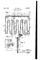
Figure l represents, diagrammatically, a transmitting system embodying the invention;
Figure 2 is an enlarged diagrammatic crosssectional view taken along line 2-2 of Figure l; and
Figure 3 is an enlarged perspective view of a record carrier with its record carrying a single code group together with a portion of the supporting structure.
In the transmitting system illustrated in the drawings, an individual sound record is prepared for each subscriber who is identified, for example, by a three-digit code number. Such a record with its carrier is indicated generally at 2 in Figure 3. The record is formed by sound signals recorded optically on photographic nlm, as indicated at 4, which is secured to the surface of, or encased in, a strip 6 of clear solid material, such as glass or plastic. The opacity of the photographic nlm 4 varies along its length in accordance with the voice signals so that when the cord 2 is moved longitudinally so as to intercept a beam of light between a light source 8, see Figure 1, and a photocell I0, the current through the photocell I0 varies in accordance with the voice signals recorded on the film 4.
As best shown in Figure 3, each of the strips 6 is provided with a transverse slot I2 near one end, this slot being suiciently llong that the record 2 can be placed on a hook-supporting member I4, which extends horizontally outwardly from a link I6 that is in turn pivotally supported by a horizontal rod I8. This rod I8 is supported by a double-link chain, generally indicated at 20, in `Figures 1 and 3.
This endless chain 20 passes successively over a series of sprockets 22, and is driven in the direction indicated by the arrows 40 by means of a drive sprocket 42 which is connected through a speed-reducing gear assembly, indicated diagrammatically at 44, to an electric motor 45..
The record-supporting arms I4 are carried by the chain 20 at regularly spaced intervals throughout the length of the chain 20, the spacing being suicient to permit easy identification of each separate code group as they are broadcast in succession.
As the chain 20 moves along the lower portion of its endless path, the records 2 hang vertically from the supporting arms I4, but after passing the sprocket 22', the records are dragged horizontally across the surface of a table 48 so as to pass between the light source 8 and the photocell I0.
The supporting structure for the record carriers as they are moved. across the surface of the table 48 is shown best in Figure 2. During this portion of the movement of the chain 20, the central portions of the links of the chain are supported by upper parallel surfaces of a double track, generally indicated at 5i), carried by the table 48. In order to support and guide the record carriers 2, each record carrier includes a metal strip 52 (see also Figure 3) which extends longitudinally along the plastic strip 6 to which it is secured, for example by rivets 54. This metal strip 52 is narrower than the plastic strip 6 so that the edge of this strip 6, which supports the lm 4 that carries the recorded sound signals, extends beyond the edge of the metal strip Elfi. When the record carrier is moved across the table 48, the metal strip 52 is on the under side of the plastic strip E5 and moves along a channel formed by two longitudinal members 56 and 58 of L- shaped cross section. rhus, the metal strip 52 guides the4 record carrier along this track so that its movement is coniined to a linear path with no substantial amount of side moveA lent, the rec ord carrier 2 being supported by the metal strip' 52 so that the plastic record support 5 does not make frictional contact with the track members 56 or 5t, thus avoiding any wearer abrasion of the surfaces of the nlm fi or plastic strip which would interfere with the operation of the opticall reproducing system. The strip is provided with a vertical opening which is aligned with a lens system, generally indicated at iid, sothat light from the source 8 passes through the lens system: through the vertical opening iii in the track member 55, andA is focused on the sound nlm strip 4", the rays oi" light emerging through the transparent strip E, and iinpinging on the photocell i0.
Thus, as the record carrier 2' moves across the surface oi" the table 5.18, the sound track t intercepts' the light beam' producing variations in the current through the photocell Ill which are amplified by an amplifier, indicated in block form at 52 in Figure l, and fed'into a radio transmitter, indicated in block form at et, where they are used to modulate the radio signal. The ampliner E2 and transmitter- Gli' may be o'aiiy conventional type, using either amplitude or frequency modulation, The transmitter @il is connected to a conventional antenna arrangement Gli, by which the signal is broadcast so that it can be picked up bythe receivers in. the possession or the individual subscribers.
In this particular example, an optical recording system has been utilized for the purposesof illustrating the principles of operation of the invention, but it is clear that other known recording systemscan beutilized'.
When a subscriber is called, the operator momentarily stops the endless Chain 2d' and places a record carrying. that particular subscribers code group on one of the supporting arms Hi.
Thus, the transmitter automatically broadcasts in continually-repeating cycles the selected code signals of the records which have been placed on the chain. The convolutions of the chain 2Q over the sprockets 22 provides suiiicient length of chain to accommodate the maximum number of codagroups which it may be` desired to broadcast in any one cycle. When a subscriber answers his call, the operator. momentarily stops the endless chain 253 and removes that particular subscribers record carrier from the chain.
From the foregoing, it will be apparent that the embodiment of the invention described herein. is well adapted to attain the ends and objects hereinbefore set forth, and that it may be readily'modified in accordance with the principles set forthherein so as tobest suit the requirements of each particular use.
I claim:
1. In an automatic paging system wherein parties to. be paged are designated respectively by distinctive audio code signals, apparatus comprising a plurality of separate sound records each having recorded thereon a distinctive code group, a conveyor for removably supporting said records in. successive positions along an endless path, a
sound reproducing device cooperating with said records, motor-driven means drivably connected to said conveyor to move said records successively into operative position With respect to said reproducing device in continually repeating cycles and in the order in which said record carriers are positioned on said conveyor, and a table for supporting said' records arranged to provide vertical and horizontal guidance of said records as they are moved sequentially through said operative position.
2. Iiiian automatic paging system wherein parties to be paged are designated respectively by distinctive audio code signals, apparatus comprising a plurality of separate sound records each having recorded thereon a distinctive audio code group. and having a record-supporting guide strip,
` a chain-link conveyor for removably supporting said records in successive positions along an endless path, a sound reproducing device cooperating with said records, motor-driven means drivably connected tol saidy conveyor to move said recordsr successively intooperative position. with respect to said reproducing device in continually repeat'- ing cycles and in the order iir whichv said record carriers are positioned onsaid conveyor, and a table for supporting said records and having: a. linear track arranged to receive said guideV strips and to provide vertical andv horizontal guidance1 of said records as they are' moved sequentially through said operative'position.
3. In an automatic paging system whereinv parties to be paged are designated respectively by distinctive audio code-signals, apparatus comprising a plurality of separate sound' records-eachy including a sound iilm` record oi" a f listirictivey code group, a transparent plastic strip supporting said sound nlm, and a metal. guide strip secured to said plastic strip and extending paraliclf with said sound lm, an endless chain conveyor' havingy spaced outwardly-extending armsfor removably and swingably supportinOr said= records' in successive positionsalongv an endless path, optical sound-reproducing means, motor-driven means for moving said conveyor, said conveyor being arranged to position each o said recordsv succes'- sively'into operative position with respect to` said reproducing means in continually repeating cycles and in the order in which said record" carriers are positioned on said conveyor, and a track arranged to receive said metal guide strips' of said records to provide vertical supportand horizontal guidance of said'records as they are movedsequentially therealong by said conveyor through said operative position.
l. In an automatic paging system wherein' parties to be paged are designatedy respectively by distinctive audio signals, apparatus comprising a plurality of separate sound records having predeterminedaudio signal: groups recorded thereon, conveyor means moving along an` endless path for supporting said records, automatic repeater means including a sound reproducer cooperating with said records for reproducing said signals and means for producing relative scanning movement between said conveyor means andv said soundzreproducer arranged to produce selectively and repeatedly in continual cycles selected: portions` of said signal groups, and means for removably securing said records to said conveyor means.
75. For use in an automatic paging system wherein a changeable series of codegroups are reproduced byla reproducing and transmitting fystem in continually repeatingI cycles; a recordY roi carrying a distinctive code; group, comprising a transparent record carrier, a linear record element having variable light transmission properties along its length in accordance with predetermined audio code signals, means securing said record element to said transparent carrier, and a record guide strip secured to said record carrier and extending parallel to said record element for supporting said record during reproduction, said record being adapted to ride in a complementarily dimensioned guideway.
6. For use in an automatic announcement system, a sound record comprising a transparent plastic strip, a sound film secured to said transparent strip and extending parallel with and adjacent one edge thereof, and a metal runner extending lengthwise of and secured to said strip for supporting and guiding said record during reproduction, said runner being adapted to ride in a complementarily dimensioned guideway.
7. In a sound reproducing system including a sound reproducing head; apparatus comprising, a conveyor, a plurality of individual elements mounted on said conveyor, said elements each having a distinctive group of audio sounds recorded thereon, means for moving said conveyor and said reproducing head relative to each other, and means for guiding said elements into operative sound reproducing relationship with said head.
8. In a paging system including a sound reproducer, apparatus comprising, a movable support, a plurality of individual elements, said elements each having a distinctive group of audio sounds recorded thereon, means on said support and on said elements for readily removably mounting said elements on said support in a plurality of various positions, means for moving said sound reproducer and said support relative to each other, and means for coordinating movement of said elements with respect to said sound reproducer so that said sound reproducer can reproduce the recordings on said individual elements.
9. In a paging system including a sound reproducer; a record for said sound reproducer comprising, a support having a plurality of positions for locating elements thereon, a plurality of individual elements readily removably attached to said support at at least a portion of the positions, said elements each having a distinctive group of sounds recorded thereon; means for causing relative movement in repeating cycles of said record and said sound reproducer; and means for coordinating movement of said elements with respect to said sound reproducer so that said sound reproducer can reproduce the recordings on said individual elements.
10. For use in an automatic paging system, a record to be played in continually repeating cycles comprising a support, a plurality of individual elements having distinct sounds recorded thereon, and means for readily removably mounting said elements in successive positions to said support, said elements having guide means for tracking said elements through a sound reproducer.
WALTER ROBERT HICKS.
References Cited in the le of this patent UNITED STATES PATENTS Number Name Date 2,002,352 Owens 4 May 21, 1935 2,212,970 Finch Aug. 27, 1940 2,215,468 Herzig Sept. 24, 1940 2,488,840 Wells Nov. 22, 1949
Priority Applications (1)
| Application Number | Priority Date | Filing Date | Title |
|---|---|---|---|
| US254115A US2640887A (en) | 1951-10-31 | 1951-10-31 | Automatic paging system |
Applications Claiming Priority (1)
| Application Number | Priority Date | Filing Date | Title |
|---|---|---|---|
| US254115A US2640887A (en) | 1951-10-31 | 1951-10-31 | Automatic paging system |
Publications (1)
| Publication Number | Publication Date |
|---|---|
| US2640887A true US2640887A (en) | 1953-06-02 |
Family
ID=22962985
Family Applications (1)
| Application Number | Title | Priority Date | Filing Date |
|---|---|---|---|
| US254115A Expired - Lifetime US2640887A (en) | 1951-10-31 | 1951-10-31 | Automatic paging system |
Country Status (1)
| Country | Link |
|---|---|
| US (1) | US2640887A (en) |
Citations (4)
| Publication number | Priority date | Publication date | Assignee | Title |
|---|---|---|---|---|
| US2002352A (en) * | 1933-03-21 | 1935-05-21 | Freeman H Owens | Sound film apparatus |
| US2212970A (en) * | 1938-11-16 | 1940-08-27 | William G H Finch | Multistylus facsimile recorder |
| US2215468A (en) * | 1937-04-24 | 1940-09-24 | Lon Ga Tone Inc | Sound recording and reproducing apparatus |
| US2488840A (en) * | 1945-08-17 | 1949-11-22 | John W Wells | Time announcing apparatus |
-
1951
- 1951-10-31 US US254115A patent/US2640887A/en not_active Expired - Lifetime
Patent Citations (4)
| Publication number | Priority date | Publication date | Assignee | Title |
|---|---|---|---|---|
| US2002352A (en) * | 1933-03-21 | 1935-05-21 | Freeman H Owens | Sound film apparatus |
| US2215468A (en) * | 1937-04-24 | 1940-09-24 | Lon Ga Tone Inc | Sound recording and reproducing apparatus |
| US2212970A (en) * | 1938-11-16 | 1940-08-27 | William G H Finch | Multistylus facsimile recorder |
| US2488840A (en) * | 1945-08-17 | 1949-11-22 | John W Wells | Time announcing apparatus |
Similar Documents
| Publication | Publication Date | Title |
|---|---|---|
| DE3175265D1 (en) | Track searching arrangement for an optical information recording and reproducing apparatus | |
| ES8200961A1 (en) | Record carrier containing information in an optically readable information structure, as well as apparatus for reading said carrier. | |
| FR2488431B1 (en) | METHOD AND APPARATUS FOR RECORDING DIGITAL INFORMATION ON A RECORDING MEDIUM | |
| AU2161777A (en) | Focussing system inan apparatus for optically reading a record carrier | |
| DE3853330D1 (en) | Automatic changer for digital audio cassette tape player. | |
| ATE36617T1 (en) | OPTICAL RECORDER. | |
| WO1987007752A1 (en) | Pickup transfer device of an optical disk apparatus | |
| AU505466B2 (en) | Centring system inan apparatus for optically reading a record carrier | |
| FR2304137A1 (en) | REPRODUCING DEVICE, IN PARTICULAR A VIDEO TURNTABLE, FOR REPRODUCING INFORMATION FROM DISCS EQUIPPED WITH INFORMATION TRACKS | |
| DE3477859D1 (en) | Apparatus for reproducing information from an optically readable record carrier | |
| US3640479A (en) | Cassette tape device | |
| DK147840C (en) | PROCEDURE FOR RECORDING PERIODIC VIDEO SIGNALS ON A MAGNETIC INFORMATION CARRIER AND APPARATUS FOR RECORDING AND REPRESENTING SUCH SIGNALS | |
| US2640887A (en) | Automatic paging system | |
| US3766328A (en) | Slant track rotating head recorder-reproducer system for selective retention of special information | |
| US2604549A (en) | Device for duplicating magnetic recordings by re-recording processes | |
| US3059348A (en) | Method and apparatus for teaching languages | |
| ES8102398A1 (en) | Recording and/or reproducing apparatus. | |
| GB2087628B (en) | Apparatus for recording data in a discshaped optically readable record carrier | |
| JPS53117402A (en) | Video disc | |
| US2115503A (en) | Mechanism for winding endless films | |
| DK137735B (en) | Record carrier, where information is recorded in an optical structure, and apparatus for recording information on such a record carrier. | |
| GB2085635B (en) | Disc record reproducing apparatus with turntable adjusting mechanism | |
| US2348050A (en) | Spotting and signaling apparatus | |
| DE69126160D1 (en) | Optical information recording / reproducing apparatus | |
| US2420802A (en) | Selective-speed telegraph code instruction system |