US2640407A - Automobile heater - Google Patents
Automobile heater Download PDFInfo
- Publication number
- US2640407A US2640407A US105552A US10555249A US2640407A US 2640407 A US2640407 A US 2640407A US 105552 A US105552 A US 105552A US 10555249 A US10555249 A US 10555249A US 2640407 A US2640407 A US 2640407A
- Authority
- US
- United States
- Prior art keywords
- duct
- air
- heater
- valve
- casing
- Prior art date
- Legal status (The legal status is an assumption and is not a legal conclusion. Google has not performed a legal analysis and makes no representation as to the accuracy of the status listed.)
- Expired - Lifetime
Links
Images
Classifications
-
- B—PERFORMING OPERATIONS; TRANSPORTING
- B60—VEHICLES IN GENERAL
- B60H—ARRANGEMENTS OF HEATING, COOLING, VENTILATING OR OTHER AIR-TREATING DEVICES SPECIALLY ADAPTED FOR PASSENGER OR GOODS SPACES OF VEHICLES
- B60H1/00—Heating, cooling or ventilating devices
- B60H1/00007—Combined heating, ventilating, or cooling devices
- B60H1/00021—Air flow details of HVAC devices
- B60H1/00035—Air flow details of HVAC devices for sending an air stream of uniform temperature into the passenger compartment
- B60H1/00042—Air flow details of HVAC devices for sending an air stream of uniform temperature into the passenger compartment the air passing only one heat exchanger
-
- B—PERFORMING OPERATIONS; TRANSPORTING
- B60—VEHICLES IN GENERAL
- B60H—ARRANGEMENTS OF HEATING, COOLING, VENTILATING OR OTHER AIR-TREATING DEVICES SPECIALLY ADAPTED FOR PASSENGER OR GOODS SPACES OF VEHICLES
- B60H1/00—Heating, cooling or ventilating devices
- B60H1/00007—Combined heating, ventilating, or cooling devices
- B60H1/00021—Air flow details of HVAC devices
- B60H2001/00078—Assembling, manufacturing or layout details
Definitions
- This invention relates to an improved heater and particularly to a heater for use in automobiles It is an object of this invention to provide a heater which has adaptability to air cooling an kdefrosting as well as heating.
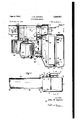
- Fig. 1 is a front view of the heater of this invention shown partly in section;
- Fig. 2 is a Vertical section of the heater taken on line 2 2 of Fig. 1 in the direction of the arrows;
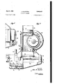
- Fig. 3 is a plan view of the heater partly in horizontal section taken on line 3-3 of Fig. 2;
- Fig. 4 is an enlarged horizontal section ofa portion of the core and casing of the heater showing a modification of the core supporting means.
- this invention lcoi'nprises a heater providing simplicity in operation, adaptability to air cooling, defrosting or heating, andrease of manufacture.
- a heater I having a casing II has extending from the left side of the casing II as shown in Fig. 1 a duct I2. Fromthe upper surface of the casing Il two defroster ducts I3 extend perpendicularly and side by side to receive twor defroster tubes (not shown). Also on the upper surface of the casing I I is a recirculation intake duct i4 having .a control valve I5 actuated by a crank IS. Control valves I'I for the control ducts I3 are shown in dotted outline and are mounted on a shaft I8 which is turned by a crank I3. A valve 20 con- ⁇ trolling the flow of air into duct I2 is turned by acrank2
- the casing I I is shown to have two parts,A ajfront half 22 and a rear half 23. Inside of these twoisections of the casing is a core 24 in which extend'two circulation pipes 25 ⁇ which may be connected to the cooling jacket of the automobile enginey for the supply of flowing heated water to the core 24.
- a wall 26 is the wall between the body compartment and the engine compartment of the automobile. The wall 26 will hereinafter bereferred to as the fire wall 26.
- the heating assembly IU is secured to the re wall 26 by bolts 3,5 and nuts 3S. The position ofA the bolts 35v is merely suggestive.
- a ring 21 through an aperture in the re wall 26 connects the interior of the casing II' to the interior of a blower casing 28.
- the blower casing 28 contains a blower fan 29 driven by a suitable motor 30.
- shown above the blower 29 has a fianged port 32 which extends down and encloses a rim 33 around an aperturevin the' upperv surface of the blower casingk28. The fresh air is drawn into the heating system from the forward part of the automobile through a forwardly ei;- tending portion'34 of the duct 3l.
- The'air is drawn into the blower through port 32 and past rim 33 and is expelled by the blower 29 from the lower casing 28 through the ring- 2'I into the heater casing II and against the core 24.
- the distribution of air to the body compartment is effected through the vertical slots 49 in the duct I2 and the end louvre openings 50.
- a small slot 5I may be provided in the bottom surface rof ⁇ the casing II to provide a bleeding on" of air to the Ybody compartment when the flap 20 closes the through the slots 49 and louvre 50.
- the air passes through interstices in the core 24 and becomes warmed.
- the recirculation intake I4 on the top of the casing Il has an intake opening 31 and an exit port 38 discharging into a rearwardly extending duct 39 of the duct 3l.
- the valve I5 controls the passage of air through the intake opening ⁇ 3'I. Referring to the plan view of Fig. 3, the valve tached 't'o the crank I6 holds the valves I5 and 42 in a normally predetermined position in which valve I5 is fully closed and valve 42 is fully opened.
- the forward extending duct 34 carries fresh air to the heater from the forward part of the car in the vicinity of the radiator.
- a valve not shown is provided at some point in the pipes 25. This valve can either shut on completely or decrease the how of water through the pipes 25v and consequently the core 2.
- This valve is remotely controlled as by a Bowden wire. If iresh cool air alone is desired the heater Ic may be used to supply the body compartment with fresh cool air during the warin periods of the year simply by setting in closed position a control of the circulation of heating liquid through the core and allow the core to remain cool.
- the blower lfan 29, duct system 3l and distribution duct I2 and slot 5l then serve to cool the body compartment. and thus serve a dual purpose.
- The. heater is thus simple and yet adaptable to heating, defrosting and air cooling.
- valve i5. controls the entry of air through the intake 3i. oi the recirculation duct. Ui while valve. t2 controls. the passage of air through the forward, extending duct 34.
- rIfhev valves 5.5 and al as. mentioned above are connected and mutually controlled through a rod 40. and cooperating crank arms. l and il on the straight shanks oi whichl the valves. l5 andd. are mounted.
- valves I- and lil are. so mounted on the. cra-nk arms i5 and di. that. when v-mve I5 is fully opened valve 42. fully closed and vice versa.
- valve l5 is half. onen valve, d2 is also at the half-way position ⁇
- the Bowden wire fill whose iexihle, coverh'ig 5.3 issu-itably anchored has. a moving. wire 5,2. which being attached to ⁇ crank arm. 46 operatesv theentire Qontrol valve assembly for therecircnlating intake I@ and the iorwardly extending, duct, 34. as the central wire 52. is advanced irozn. its. flexible covering 5.3.
- crank arm te rotated .ciilnterolockwise moving the valve t5. in asimilasv direction openthe.- intake port 3l, simu-l- -tancouslythe. rod Ll is moved. in a forward. direc.-
- valves I5 and 42 through rod link Gt, therefore not only decreases the amount of air that is drawn through duct St as the port Si' is opened but also increases the suction created through port 31 as this port is opened.
- the desired action in closing the valve itil and opening the valve I5 is therefore increased by the cooperation of these parts.
- the decrease of the suction through the intake port El increases the suction pressure exerted through the duct 3c and assists the intake of fresh air from the front of the car.
- the core 24 isv held in position in the casing I I by studs 5d.
- These studs 541 are made up of bases t5 which are integral with the casing wall and onto which removable projections i6 may be tted and secured.
- the projection :SS is fastened in this modiiication to the base i5 by a threaded lug 4T on the projection it screwing into a threaded recess d8 in the base 45.
- Cores having variations in the depth dimension may be tted into a uniform sized casing by substitution of projection portions t6 of various compensating lengths on the bases d5 in the uniform sized casing II.
- the casing l could be adapted to receive and securely hold such narrower core by inserting stud projections iiS of greater length which would take up the space and hold the studded core as securely as the core shown in therois.
- the valves I 'I cooperate synchronously ⁇ with the valve 2B through a rod link d3 which connects cranks la and 2l.
- the positioning of the rod link d3, the cranks. I9 and 2l andthe valves il and 2B may be accomplished, in any desired manner by crank, knob, or otherwise,l including control by suitable power apparatus.
- the valves il are fully opened and the valve 25 is fully closed. In this. position all of the output oi the heater core 244 would be delivered to the derosters.
- valve 2li is fully opened and valves. L'I are fully closed. In this. way the opening and closing or the valves il and the valve 2.5; are synchronized.
- a delivery of the entire output of the heated air can be: made to the defrcster tubes.
- concentration of heat isno-t necessary the supply or' heat to: the defrostertubes; can. be. slowly diminished and the excess heated air be: fed into duct I2'.
- the duct I2' is cast integrally with the casingv I-I..
- the duct I:2 therefore has a front half which is integral with front half- 22! of? the casing and ⁇ has a rear half which is integral with rear half 23 of the casing.
- the valve 2li is mounted on. a. shaft. 55 of the crank ZI.
- the shaft: 55 is held' in position in the ductl Il2-Y between the front half 22 and the rear Vhalf 23- of the duct l2.
- Recesses 56 in the wall of the duct I2 at the point of securing the shaft 55 act as bearings for the shaft 55.
- the two halves of the casing Il and the duct l2 are suitably held together.
- a heater is provided in which the only parts of the heater within the body compartment are the heater core and distribution duct and defroster tubes. Yet it is possible to provide recirculation with the heater of this invention without a second opening for passage of air through the fire wall. This is of importance as automobiles are manufactured with a single aperture through the i'lre wall. To cut another aperture through the nre wall would be troublesome. At the same time the recirculation of the air in the body compartment and the cutting ofi of the draft of fresh cool air from outside of the body compartment is an important feature.
- This invention advantageously supplies a heater having the motor and blower of the heater outside the body compartment, a duct drawing air from the front of the engine compartment, and a recirculation duct carrying air from the body compartment through the blower and back into the heating core through a single aperture in the separating wall between the engine and body compartments.
- valves which control the supply of air to the blower cooperate to maintain a delivery of a certain minimum volume of air to the blower. Without this minimum the blower does not operate efciently. However, if too much air is supplied to the blower the heater core cannot provide a satisfactory degree of warmth to the air. It is therefore imperative that without regard to where the air is drawn f-rom, either uncirculated or recirculated, that the overall volume ⁇ be maintained in a certain range, This is achieved by synchronous cooperation in the movement of the control valves I5 and 42. Similarly, the synchronous operation of the valves I1 and 20 provides an eicient distribution of the heated air to the body compartment.
- An automobile heater cooperable with the re wall of an automobile passenger body including in combination a duct system combined with a blower casing in the motor compartment adjacent said fire wall; a rotary blower fan in said casing; a central duct in said duct system adjacent and.
- valve means for controlling thel introduction of air to said duct system, said casing and said blower fan through said entrance orifice and additional valve means for controlling the introduction of air to said duct system, said casing and said blower fan through said second duct, means attached to the respective valve means to actuate said valve means so that as the one valve closes the other opens and vice versa whereby air may be drawn from said passenger compartment through said second duct and through said blower fan alone or together with air from said entrancegna fand then through said ring to said passenger compartment and said heater core in a direction opposite
Landscapes
- Physics & Mathematics (AREA)
- Thermal Sciences (AREA)
- Engineering & Computer Science (AREA)
- Mechanical Engineering (AREA)
- Air-Conditioning For Vehicles (AREA)
Description
l Filed July 19; 1949 June 2, 1953 `.L M. AUFIERQ 2,640,407
AUTOMOBILE HEATER,
2 Sheets-Sheet l JNVENToR. .BY ft/HJM 17a/Yer@ om@ 'W1 HTTORNEYS June 2, 1953 J. M. AuFlERo v .2,640,407
AUTOMOBILE HEATER v Filed July 19, -1949 2 sheetsheet 2 'LAVA VIIIIIIIIIIII, N
INVENTOIL [MQ wam Patented June 2, 1953 AUTOMOBILE HEATER John M. Auiero, Plandome, N. Y., assignor to E. A. Laboratories, Inc., Brooklyn, N. Y., a corporation of New York v Application July 19, 1949, Serial No. 105,552
1 Claim.
1 e This invention relates to an improved heater and particularly to a heater for use in automobiles It is an object of this invention to provide a heater which has adaptability to air cooling an kdefrosting as well as heating.
It is another object of this invention to provide a structure which can be adjusted to receive Icores of different sizes.
v It is a further object of this invention to proj vide a heater in which the motor moving the air is on one side of the dividing wall between the -engine and passenger compartments and the ducts delivering the heated air are on the other.` side of such dividing Wall.
It is still another object of this invention to provide a unit which includes relatively few parts 'each individually simple and rugged in construction andcapable of manufacture by quantity production; such parts when assembled operatn ing over long periods of time with freedom from 'and in which:
Fig. 1 is a front view of the heater of this invention shown partly in section;
Fig. 2 is a Vertical section of the heater taken on line 2 2 of Fig. 1 in the direction of the arrows;
Fig. 3 is a plan view of the heater partly in horizontal section taken on line 3-3 of Fig. 2; and
Fig. 4 is an enlarged horizontal section ofa portion of the core and casing of the heater showing a modification of the core supporting means.
In general this invention lcoi'nprises a heater providing simplicity in operation, adaptability to air cooling, defrosting or heating, andrease of manufacture.
Referring to Fig. 1, it will be seen that a heater I having a casing II has extending from the left side of the casing II as shown in Fig. 1 a duct I2. Fromthe upper surface of the casing Il two defroster ducts I3 extend perpendicularly and side by side to receive twor defroster tubes (not shown). Also on the upper surface of the casing I I is a recirculation intake duct i4 having .a control valve I5 actuated by a crank IS. Control valves I'I for the control ducts I3 are shown in dotted outline and are mounted on a shaft I8 which is turned by a crank I3. A valve 20 con- `trolling the flow of air into duct I2 is turned by acrank2|.
Referring to the vertical section of Fig. 2,'1the casing I I is shown to have two parts,A ajfront half 22 and a rear half 23. Inside of these twoisections of the casing is a core 24 in which extend'two circulation pipes 25 `which may be connected to the cooling jacket of the automobile enginey for the supply of flowing heated water to the core 24. A wall 26 is the wall between the body compartment and the engine compartment of the automobile. The wall 26 will hereinafter bereferred to as the fire wall 26. The heating assembly IU is secured to the re wall 26 by bolts 3,5 and nuts 3S. The position ofA the bolts 35v is merely suggestive. A ring 21 through an aperture in the re wall 26 connects the interior of the casing II' to the interior of a blower casing 28. The blower casing 28 contains a blower fan 29 driven by a suitable motor 30. An air duct system 3| shown above the blower 29 has a fianged port 32 which extends down and encloses a rim 33 around an aperturevin the' upperv surface of the blower casingk28. The fresh air is drawn into the heating system from the forward part of the automobile through a forwardly ei;- tending portion'34 of the duct 3l. The'air is drawn into the blower through port 32 and past rim 33 and is expelled by the blower 29 from the lower casing 28 through the ring- 2'I into the heater casing II and against the core 24. lThe distribution of air to the body compartment is effected through the vertical slots 49 in the duct I2 and the end louvre openings 50. A small slot 5I may be provided in the bottom surface rof `the casing II to provide a bleeding on" of air to the Ybody compartment when the flap 20 closes the through the slots 49 and louvre 50.'
The air passes through interstices in the core 24 and becomes warmed. The warmedr air urged by the pressure from the blower fan 29escapes from the casing II through the defrosterjducts duct I2 and prevents the escapeof heatedl air I3, the slot 5I and duct I2 whence it-is distributed through the body compartment. y v
The recirculation intake I4 on the top of the casing Il has an intake opening 31 and an exit port 38 discharging into a rearwardly extending duct 39 of the duct 3l. The valve I5 controls the passage of air through the intake opening `3'I. Referring to the plan view of Fig. 3, the valve tached 't'o the crank I6 holds the valves I5 and 42 in a normally predetermined position in which valve I5 is fully closed and valve 42 is fully opened.
The forward extending duct 34 carries fresh air to the heater from the forward part of the car in the vicinity of the radiator. A valve not shown is provided at some point in the pipes 25. This valve can either shut on completely or decrease the how of water through the pipes 25v and consequently the core 2. This valve is remotely controlled as by a Bowden wire. If iresh cool air alone is desired the heater Ic may be used to supply the body compartment with fresh cool air during the warin periods of the year simply by setting in closed position a control of the circulation of heating liquid through the core and allow the core to remain cool. The blower lfan 29, duct system 3l and distribution duct I2 and slot 5l then serve to cool the body compartment. and thus serve a dual purpose. The. heater is thus simple and yet adaptable to heating, defrosting and air cooling.
The occasion may arise, howeven, when introducing air in through duct'. 34 should be limited either because it is tco cold to be adequately heated by the corey to provide a desired degree. of warmth, or because of congested traffic or for other reasons. it is not desired to draw air from in front oi the automobile. Under these circumstances it is best. to close oil the forward extending duct 34 and draw the air for heating purposes out of the body compartment through the blower and core. This may be done by recirculating air from the body campartmentthreinh the blower 2S and the heater core 2c and provide a more rapid and more eiiicient heating or the air in the body compartment. The arrangement of the ductv 32 with its forwardly extending portion 34. and rearwardly extending portion Se. and the recirculation intake id is. such as, to be able to. vfeed air either. irorn the iront of, the car or the body compartment. through the blower and heater casingy il equally easily and efciently. .esJ shownin Figs. 2. and 3.. valve i5. controls the entry of air through the intake 3i. oi the recirculation duct. Ui while valve. t2 controls. the passage of air through the forward, extending duct 34. rIfhev valves 5.5 and al as. mentioned above are connected and mutually controlled through a rod 40. and cooperating crank arms. l and il on the straight shanks oi whichl the valves. l5 andd. are mounted. The valves I- and lil are. so mounted on the. cra-nk arms i5 and di. that. when v-mve I5 is fully opened valve 42. fully closed and vice versa. Similarly, when valve l5 is half. onen valve, d2 is also at the half-way position` The Bowden wire fill whose iexihle, coverh'ig 5.3 issu-itably anchored has. a moving. wire 5,2. which being attached to` crank arm. 46 operatesv theentire Qontrol valve assembly for therecircnlating intake I@ and the iorwardly extending, duct, 34. as the central wire 52. is advanced irozn. its. flexible covering 5.3. the crank arm te rotated .ciilnterolockwise moving the valve t5. in asimilasv direction openthe.- intake port 3l, simu-l- -tancouslythe. rod Ll is moved. in a forward. direc.-
-tion-l rotating; crank` arm` it also. in a counterclockwiseV direction. and. the valve it in. av counterclockwise direction. to: close the forward.. extending-g duct 3d. rihus a delicate-controloi thepositions-oi valvesr t5: and cfmaybe-obtained through the Bowden wire Eli. As the valve is; in the port` 3.7 is opened' a suction is createdv through the port 3i by the blower.' This suction is aided by the blocking of the entry of air through duct 3e. The cooperation of the valves I5 and 42 through rod link Gt, therefore not only decreases the amount of air that is drawn through duct St as the port Si' is opened but also increases the suction created through port 31 as this port is opened. The desired action in closing the valve itil and opening the valve I5 is therefore increased by the cooperation of these parts. Conversely, on closing valve I5 and opening valve 42 the decrease of the suction through the intake port El increases the suction pressure exerted through the duct 3c and assists the intake of fresh air from the front of the car.
The core 24 isv held in position in the casing I I by studs 5d. These studs 541 are made up of bases t5 which are integral with the casing wall and onto which removable projections i6 may be tted and secured. Asy shown in the section of Fig. 4, the projection :SS is fastened in this modiiication to the base i5 by a threaded lug 4T on the projection it screwing into a threaded recess d8 in the base 45. Cores having variations in the depth dimension may be tted into a uniform sized casing by substitution of projection portions t6 of various compensating lengths on the bases d5 in the uniform sized casing II. Iihus in the case o the heater IG shown, if it were desired to insert a core having a narrower dimension from A to B asv shown in Fig. 4, the casing l could be adapted to receive and securely hold such narrower core by inserting stud projections iiS of greater length which would take up the space and hold the studded core as securely as the core shown in the heures.
The valves I 'I cooperate synchronously` with the valve 2B through a rod link d3 which connects cranks la and 2l. The positioning of the rod link d3, the cranks. I9 and 2l andthe valves il and 2B may be accomplished, in any desired manner by crank, knob, or otherwise,l including control by suitable power apparatus. As shown in Fig. 3, the valves il are fully opened and the valve 25 is fully closed. In this. position all of the output oi the heater core 244 would be delivered to the derosters. By moving rod link 43 rearwardly the crank` 2l is. rotated clockwise as seen in Fig. 3. and the crank I9 is rotated upwardly as seen. in Fig. 3. This motion simultaneously closes the valves I'i and opens the valve 2G. At the full completion. of the motion of the rod. link i3 away from the position show-n in Fig. 3, valve 2li is fully opened and valves. L'I are fully closed. In this. way the opening and closing or the valves il and the valve 2.5; are synchronized. Thus, when desired, a delivery of the entire output of the heated air can be: made to the defrcster tubes. However, when such a concentration of heat isno-t necessary the supply or' heat to: the defrostertubes; can. be. slowly diminished and the excess heated air be: fed into duct I2'. In stating that the. full supply'I of` the output of the core Ecl isA directed into tlredefroster tube it is borne in mind-z that: there will be a1 certain. limited; escape off heated air to the body compartment through the. slot; 5I- when thevalve t2 is-completelyclosed.
The duct I2' is cast integrally with the casingv I-I.. The duct I:2 therefore has a front half which is integral with front half- 22! of? the casing and` has a rear half which is integral with rear half 23 of the casing. The valve 2li is mounted on. a. shaft. 55 of the crank ZI. The shaft: 55 is held' in position in the ductl Il2-Y between the front half 22 and the rear Vhalf 23- of the duct l2. Recesses 56 in the wall of the duct I2 at the point of securing the shaft 55 act as bearings for the shaft 55. The two halves of the casing Il and the duct l2 are suitably held together. Thus a simple construction is provided whereby the assembly of the two halves of the casing and duct serves also to clamp and secure the vaive 20 in position.
Thus the many advantages of the heater of this invention are achieved. A heater is provided in which the only parts of the heater within the body compartment are the heater core and distribution duct and defroster tubes. Yet it is possible to provide recirculation with the heater of this invention without a second opening for passage of air through the fire wall. This is of importance as automobiles are manufactured with a single aperture through the i'lre wall. To cut another aperture through the nre wall would be troublesome. At the same time the recirculation of the air in the body compartment and the cutting ofi of the draft of fresh cool air from outside of the body compartment is an important feature. This invention advantageously supplies a heater having the motor and blower of the heater outside the body compartment, a duct drawing air from the front of the engine compartment, and a recirculation duct carrying air from the body compartment through the blower and back into the heating core through a single aperture in the separating wall between the engine and body compartments.
Among other advantages of this invention is the adjustability provided for the mounting of the heater core in the casing. A simplicity of manufacture is created as a result of this adjustability, as it will be possible to mount various sized cores in a single standard sized coring.
Further advantages of this invention are found in the synchronous operation of the control valves. The valves which control the supply of air to the blower cooperate to maintain a delivery of a certain minimum volume of air to the blower. Without this minimum the blower does not operate efciently. However, if too much air is supplied to the blower the heater core cannot provide a satisfactory degree of warmth to the air. It is therefore imperative that without regard to where the air is drawn f-rom, either uncirculated or recirculated, that the overall volume `be maintained in a certain range, This is achieved by synchronous cooperation in the movement of the control valves I5 and 42. Similarly, the synchronous operation of the valves I1 and 20 provides an eicient distribution of the heated air to the body compartment. This is, in a manner, the converse of the synchronous cooperation of the valves l5 and 42. In the synchronous cooperation of the operation of the valves I1 and 20, the heated air is distributed so that it is always efficiently employed. 1f it is not desired to use the full delivery from the heated core, with the exception of that which bleeds through slot 5|, either through the defroster tubes or the distribution duct, it is possible to divide up the distribution of the heated air between these two escapes.
'Ihe heater of this invention has the advantage of being simple and rigid in construction and fool-proof in operation. Thus among others the several objects of the invention as specifically aforementioned are accomplished. Obviously numerous changes in construction and arrangement of the parts might be resorted to without departing from the spirit of the invention as defined by the claim.
I claim:
An automobile heater cooperable with the re wall of an automobile passenger body including in combination a duct system combined with a blower casing in the motor compartment adjacent said fire wall; a rotary blower fan in said casing; a central duct in said duct system adjacent and. axial to said blower fan; a heater core in the passenger compartment adjacent said fire wall and radial to said blower fan; a ring extending through an opening in said fire wall connecting said heater core to said casing of said blower fan; a second duct extending through said opening in said fire wall from said passenger compartment and connected to said central duct; an orice defining an entrance into said duct system on the opposite side of said central duct from said second duct for providing fresh air to said automobile heater; valve means for controlling thel introduction of air to said duct system, said casing and said blower fan through said entrance orifice and additional valve means for controlling the introduction of air to said duct system, said casing and said blower fan through said second duct, means attached to the respective valve means to actuate said valve means so that as the one valve closes the other opens and vice versa whereby air may be drawn from said passenger compartment through said second duct and through said blower fan alone or together with air from said entrance orice fand then through said ring to said passenger compartment and said heater core in a direction opposite to its original path of flow through said second duct.
JOHN M. AUFIERO.
References Cited in the file of this patent UNITED STATES PATENTS Number Name Date 1,676,021 Gould July 3, 1928 1,925,805 Holle Sept. 5, 1933 1,999,349 Augstman Apr. 30, 1935 2,131,017 Lintern et a1 Sept. 20', 1938 2,131,635 Mullen Sept. 2'7,v 1938 2,164,057 Fink June 27, 1939
Priority Applications (1)
| Application Number | Priority Date | Filing Date | Title |
|---|---|---|---|
| US105552A US2640407A (en) | 1949-07-19 | 1949-07-19 | Automobile heater |
Applications Claiming Priority (1)
| Application Number | Priority Date | Filing Date | Title |
|---|---|---|---|
| US105552A US2640407A (en) | 1949-07-19 | 1949-07-19 | Automobile heater |
Publications (1)
| Publication Number | Publication Date |
|---|---|
| US2640407A true US2640407A (en) | 1953-06-02 |
Family
ID=22306466
Family Applications (1)
| Application Number | Title | Priority Date | Filing Date |
|---|---|---|---|
| US105552A Expired - Lifetime US2640407A (en) | 1949-07-19 | 1949-07-19 | Automobile heater |
Country Status (1)
| Country | Link |
|---|---|
| US (1) | US2640407A (en) |
Cited By (9)
| Publication number | Priority date | Publication date | Assignee | Title |
|---|---|---|---|---|
| US2749829A (en) * | 1952-06-27 | 1956-06-12 | Eaton Mfg Co | Vehicle heater-ventilator apparatus |
| US2756663A (en) * | 1952-11-01 | 1956-07-31 | Gen Motors Corp | Heating and defrosting apparatus |
| US2800068A (en) * | 1952-11-06 | 1957-07-23 | Gen Motors Corp | Heating, ventilating, and windshield defrosting apparatus |
| US2934262A (en) * | 1953-07-27 | 1960-04-26 | Curtiss Wright Corp | Electronic digital computer |
| US3051393A (en) * | 1958-10-06 | 1962-08-28 | Gen Motors Corp | Vehicle heating system |
| DE4315876A1 (en) * | 1993-05-12 | 1994-04-28 | Daimler Benz Ag | Air switch for vehicle heating and air conditioning system - has pair of flaps giving open and closed positions moving about common axis |
| US5335718A (en) * | 1992-04-02 | 1994-08-09 | Ford Motor Company | Space-efficient air conditioning/heating module |
| FR2741432A1 (en) * | 1995-11-20 | 1997-05-23 | Valeo Climatisation | HEATING AND / OR AIR CONDITIONING APPLIANCE HOUSING CONTAINING A HEAT EXCHANGER |
| EP0818334A1 (en) * | 1996-07-09 | 1998-01-14 | Valeo Climatisation | Simplified housing for a vehicle heating or air conditioning device |
Citations (6)
| Publication number | Priority date | Publication date | Assignee | Title |
|---|---|---|---|---|
| US1676021A (en) * | 1927-01-31 | 1928-07-03 | Mccord Radiator & Mfg Co | Heater for motor vehicles |
| US1925805A (en) * | 1932-02-29 | 1933-09-05 | Holle Joseph | Oil temperature control apparatus |
| US1999349A (en) * | 1930-05-03 | 1935-04-30 | E A Lab Inc | Automobile heater |
| US2131017A (en) * | 1935-12-16 | 1938-09-20 | Evans Prod Co | Body and engine temperature control system for motor vehicles |
| US2131635A (en) * | 1934-03-07 | 1938-09-27 | Gen Motors Corp | Steam heater for automobiles |
| US2164057A (en) * | 1937-08-02 | 1939-06-27 | Tropic Aire Inc | Fluid control valve |
-
1949
- 1949-07-19 US US105552A patent/US2640407A/en not_active Expired - Lifetime
Patent Citations (6)
| Publication number | Priority date | Publication date | Assignee | Title |
|---|---|---|---|---|
| US1676021A (en) * | 1927-01-31 | 1928-07-03 | Mccord Radiator & Mfg Co | Heater for motor vehicles |
| US1999349A (en) * | 1930-05-03 | 1935-04-30 | E A Lab Inc | Automobile heater |
| US1925805A (en) * | 1932-02-29 | 1933-09-05 | Holle Joseph | Oil temperature control apparatus |
| US2131635A (en) * | 1934-03-07 | 1938-09-27 | Gen Motors Corp | Steam heater for automobiles |
| US2131017A (en) * | 1935-12-16 | 1938-09-20 | Evans Prod Co | Body and engine temperature control system for motor vehicles |
| US2164057A (en) * | 1937-08-02 | 1939-06-27 | Tropic Aire Inc | Fluid control valve |
Cited By (11)
| Publication number | Priority date | Publication date | Assignee | Title |
|---|---|---|---|---|
| US2749829A (en) * | 1952-06-27 | 1956-06-12 | Eaton Mfg Co | Vehicle heater-ventilator apparatus |
| US2756663A (en) * | 1952-11-01 | 1956-07-31 | Gen Motors Corp | Heating and defrosting apparatus |
| US2800068A (en) * | 1952-11-06 | 1957-07-23 | Gen Motors Corp | Heating, ventilating, and windshield defrosting apparatus |
| US2934262A (en) * | 1953-07-27 | 1960-04-26 | Curtiss Wright Corp | Electronic digital computer |
| US3051393A (en) * | 1958-10-06 | 1962-08-28 | Gen Motors Corp | Vehicle heating system |
| US5335718A (en) * | 1992-04-02 | 1994-08-09 | Ford Motor Company | Space-efficient air conditioning/heating module |
| DE4315876A1 (en) * | 1993-05-12 | 1994-04-28 | Daimler Benz Ag | Air switch for vehicle heating and air conditioning system - has pair of flaps giving open and closed positions moving about common axis |
| FR2741432A1 (en) * | 1995-11-20 | 1997-05-23 | Valeo Climatisation | HEATING AND / OR AIR CONDITIONING APPLIANCE HOUSING CONTAINING A HEAT EXCHANGER |
| EP0818334A1 (en) * | 1996-07-09 | 1998-01-14 | Valeo Climatisation | Simplified housing for a vehicle heating or air conditioning device |
| FR2750928A1 (en) * | 1996-07-09 | 1998-01-16 | Valeo Climatisation | SIMPLIFIED HOUSING FOR VEHICLE HEATING OR AIR CONDITIONING DEVICE |
| US5873779A (en) * | 1996-07-09 | 1999-02-23 | Valeo Climatisation | Casting for a heating or air conditioning apparatus for a vehicle |
Similar Documents
| Publication | Publication Date | Title |
|---|---|---|
| US4232211A (en) | Automobile auxiliary heater | |
| US2640407A (en) | Automobile heater | |
| US2237497A (en) | Air conditioner for automobiles | |
| US2235642A (en) | Vehicle ventilating and heating apparatus | |
| US4067692A (en) | Odor control device | |
| US2783978A (en) | Engine-hood-construction for automobiles | |
| US2285725A (en) | Air conditioner | |
| US2026929A (en) | Heater and ventilator for motor vehicles | |
| US2996255A (en) | Automotive heating systems | |
| US2291543A (en) | Automobile air conditioning system | |
| GB935934A (en) | Improvements in or relating to air distributor fans | |
| US1991990A (en) | Heating system for self-propelled vehicles | |
| US2151865A (en) | Heating device for motorcars | |
| US2325427A (en) | Heater and windshield defroster | |
| US2264945A (en) | Pump | |
| US2685434A (en) | Air conditioning apparatus | |
| US1673149A (en) | Portable cooling and heating device for vehicles | |
| US2253671A (en) | Vehicle heating and windshield defrosting device | |
| US2495538A (en) | Evaporative cooler | |
| US2800068A (en) | Heating, ventilating, and windshield defrosting apparatus | |
| US2503764A (en) | Fan accelerated radiator cabinet | |
| US2832277A (en) | Vehicle heating and ventilating apparatus | |
| US2300357A (en) | Combination heating and cooling unit for motor vehicles | |
| US2214165A (en) | Windshield defroster | |
| US2277870A (en) | Heater |