US2636070A - Self-locking electrical connector - Google Patents
Self-locking electrical connector Download PDFInfo
- Publication number
- US2636070A US2636070A US118025A US11802549A US2636070A US 2636070 A US2636070 A US 2636070A US 118025 A US118025 A US 118025A US 11802549 A US11802549 A US 11802549A US 2636070 A US2636070 A US 2636070A
- Authority
- US
- United States
- Prior art keywords
- locking
- self
- prong
- electrical connector
- plug
- Prior art date
- Legal status (The legal status is an assumption and is not a legal conclusion. Google has not performed a legal analysis and makes no representation as to the accuracy of the status listed.)
- Expired - Lifetime
Links
- KAKZBPTYRLMSJV-UHFFFAOYSA-N Butadiene Chemical compound C=CC=C KAKZBPTYRLMSJV-UHFFFAOYSA-N 0.000 description 6
- 239000004020 conductor Substances 0.000 description 6
- 230000000694 effects Effects 0.000 description 6
- 239000004568 cement Substances 0.000 description 4
- 229920001577 copolymer Polymers 0.000 description 4
- 239000011810 insulating material Substances 0.000 description 4
- 239000000463 material Substances 0.000 description 4
- 239000012858 resilient material Substances 0.000 description 4
- 230000009471 action Effects 0.000 description 3
- 238000010276 construction Methods 0.000 description 3
- 230000008878 coupling Effects 0.000 description 3
- 238000010168 coupling process Methods 0.000 description 3
- 238000005859 coupling reaction Methods 0.000 description 3
- 229920001971 elastomer Polymers 0.000 description 3
- 239000005060 rubber Substances 0.000 description 3
- RRHGJUQNOFWUDK-UHFFFAOYSA-N Isoprene Chemical compound CC(=C)C=C RRHGJUQNOFWUDK-UHFFFAOYSA-N 0.000 description 2
- PPBRXRYQALVLMV-UHFFFAOYSA-N Styrene Chemical compound C=CC1=CC=CC=C1 PPBRXRYQALVLMV-UHFFFAOYSA-N 0.000 description 2
- QAOWNCQODCNURD-UHFFFAOYSA-N Sulfuric acid Chemical compound OS(O)(=O)=O QAOWNCQODCNURD-UHFFFAOYSA-N 0.000 description 2
- 239000002184 metal Substances 0.000 description 2
- 229910052751 metal Inorganic materials 0.000 description 2
- 238000000465 moulding Methods 0.000 description 2
- 229920003052 natural elastomer Polymers 0.000 description 2
- 229920001194 natural rubber Polymers 0.000 description 2
- 229920001084 poly(chloroprene) Polymers 0.000 description 2
- NLHHRLWOUZZQLW-UHFFFAOYSA-N Acrylonitrile Chemical compound C=CC#N NLHHRLWOUZZQLW-UHFFFAOYSA-N 0.000 description 1
- 229910001369 Brass Inorganic materials 0.000 description 1
- RYGMFSIKBFXOCR-UHFFFAOYSA-N Copper Chemical compound [Cu] RYGMFSIKBFXOCR-UHFFFAOYSA-N 0.000 description 1
- 244000043261 Hevea brasiliensis Species 0.000 description 1
- 229920002367 Polyisobutene Polymers 0.000 description 1
- BZHJMEDXRYGGRV-UHFFFAOYSA-N Vinyl chloride Chemical compound ClC=C BZHJMEDXRYGGRV-UHFFFAOYSA-N 0.000 description 1
- 239000002253 acid Substances 0.000 description 1
- 229920000180 alkyd Polymers 0.000 description 1
- 230000004075 alteration Effects 0.000 description 1
- 238000004873 anchoring Methods 0.000 description 1
- 239000010951 brass Substances 0.000 description 1
- 239000003795 chemical substances by application Substances 0.000 description 1
- HGAZMNJKRQFZKS-UHFFFAOYSA-N chloroethene;ethenyl acetate Chemical compound ClC=C.CC(=O)OC=C HGAZMNJKRQFZKS-UHFFFAOYSA-N 0.000 description 1
- 239000012084 conversion product Substances 0.000 description 1
- 229910052802 copper Inorganic materials 0.000 description 1
- 239000010949 copper Substances 0.000 description 1
- 239000011162 core material Substances 0.000 description 1
- 239000006185 dispersion Substances 0.000 description 1
- 238000006073 displacement reaction Methods 0.000 description 1
- 230000037431 insertion Effects 0.000 description 1
- 238000003780 insertion Methods 0.000 description 1
- 238000004519 manufacturing process Methods 0.000 description 1
- 239000000203 mixture Substances 0.000 description 1
- 229920000642 polymer Polymers 0.000 description 1
- 239000003829 resin cement Substances 0.000 description 1
- 229920003051 synthetic elastomer Polymers 0.000 description 1
- 229920003002 synthetic resin Polymers 0.000 description 1
- 239000000057 synthetic resin Substances 0.000 description 1
- 239000005061 synthetic rubber Substances 0.000 description 1
Images
Classifications
-
- H—ELECTRICITY
- H01—ELECTRIC ELEMENTS
- H01R—ELECTRICALLY-CONDUCTIVE CONNECTIONS; STRUCTURAL ASSOCIATIONS OF A PLURALITY OF MUTUALLY-INSULATED ELECTRICAL CONNECTING ELEMENTS; COUPLING DEVICES; CURRENT COLLECTORS
- H01R13/00—Details of coupling devices of the kinds covered by groups H01R12/70 or H01R24/00 - H01R33/00
- H01R13/02—Contact members
- H01R13/20—Pins, blades, or sockets shaped, or provided with separate member, to retain co-operating parts together
Definitions
- the present invention relates to improvements i in electrical connectors and relates more particularly to improvements in self-locking electrical connectors which are designed and adapted to lock themselves in connected relationship with respect to a receptacle or other electrical fitting ⁇ so as to avoid accidental disconnection in the event that lengthwise strain is placed upon the wires or cable to which the electrical connector is attached:
- the present invention contemplates a unique and highly effective self-locking electrical connector having a body formed of rubber or other suitable resilient material and having projecting from the said body a pair of contactprongs and a pair of complemental locking arms movable toward the respective contact prongs into unlocking position by laterally compressing the said resilient body.
- the present invention is the rst wherein it is proposed to provide a selflocking ⁇ electrical connector having a resilient body which is laterally yieldable.
- all prior self-locking electrical connectors having transversely-yielding resilient bodies have endeavored to devolve the locking function upon the Contact prongs themselves, in which construction the lateral spacing of the contact blade has necessarily to be'altered in order to effect the locking and unlocking.
- the self-locking electrical connectors of the present invention do not require the alteration of the lateral spacing between the contact prongs, and while this latter feature in itself is not original with the present invention, the combination of such feature with the other features herein set forth, has resulted in a unique structure possessing' marked advantages over the prior art.
- One of the main lobjects of the present invention ⁇ is to provide a superior self-locking electrical connector characterized by ease and facility of use, together with reliability of operation.
- QAnother object of the present invention is to provide an electrical connector of the ⁇ character referred to which does not require the lateral movement of the contact prongs or members in order to eifect the locking and unlocking actions.l
- a further object of the present invention is to.A
- Fig. 1 is a longitudinal ⁇ sectional view taken on the line l-l of Fig. 2 and showing the parts in the positions which they assume when the locking arms are in position to interlock the electrical connector with a plug receptacle or the like;
- Fig. 2 is a transverse sectional view taken on the line 2-2 of Fig. 1;
- Fig. 3 is a longitudinal sectional view taken onV the line 3--3 of Fig. 1;
- Fig. 4 is a longitudinal sectional view similar to Fig. 1 but showing the locking arms retracted
- Fig. 5 is a transverse sectional view similar to Fig. 1 but taken on the line 5--5 of Fig. 4;
- Fig. 6 is a sectionalperspective View of the body taken on the central flatwise plane thereof.
- the particular self-locking electrical connector herein chosen for purposes of illustrating a preferred embodiment of the present invention is in the form of a double-pronged plug unit of the type adapted to be thrust into and pulled out of connection with yan electrical supply receptacle or outlet, which plug unit comprises a, resilient body generally designated by the reference character l 0, two corresponding or like contact prongs or members, each generally designated by the reference character Il, and two corresponding flexible locking arms or members, each generallyv designated by the reference character I2.
- the plug body is generally oblong in crosssection, with a pair of opposed relatively broad lateral faces Illa and a pair of opposed narrower lateral faces thereto.
- the body I0 may be formed of any suitable natural rubber or synthetic resins.
- Some of the resilient insulating materials suitable for the present purposes are:
- Plasticized vinyl chloride polymers and Y (7) Plasticized vinyl chloride-vinyl acetate Y copolymers.
- Extending axially in the inner or cord end of the body II! is a passage I3 into which is fitted the end portion of a multiple-conductor cable or cord I4 having, in the present instance, two sets of individually insulated conductors I5-I5 each preferably formed of a group of ne strands of copper or the like.
- each of the said recesses is of slotlike form in cross'section with its major crosssectional transverse dimension extending in a direction substantially perpendicular with respect to a line drawn between the tvvol recesses.
- the two said laterally spaced apart recesses I'I-I'I serve, in effect, to divide the one-piece resilient body Il) into three longitudinally extending sections or arms which are aligned, in normally spaced-apart relation, in the direction of the major cross-sectional dimension of the plug body, namelypa central spacing-arm or section I8 extending substantially in an -axial direc-tion away from the cable I4, parallel to and situated between those portions of the contact prongs or blades which are within the plug body IIJ; together with two outer flexible releasing arms or end sections ISI-I9 which are movable toward and away from each other and toward and away from the spacing arm I8 in a. manner that will hereinafter appear.
- the central prong-spacing arm is seen from the drawings to be relatively massive and unyielding.
- Respectively located in the recesses I'I-I'I in the body I9 are the inner portions of the conf tact prongs II-II before referred to and which contact prongs project at their outer ends fromV and beyond the outer end I 6 of the said body I0.
- Each of the said contact prongs may be conveniently formed up of spring brass or other suitable resilient metal, and in the instance shown is channel-like in cross-section, being formed with parallel side flanges 20-20 which are spaced from each other a distance sufficient to freely accommodate between them the companion (J1-'associated locking-arm I2.
- the said flexible locking a-rm is preferably pretensioned or biased so as to normally tend to stand in spaced relationship outwardly from its companion contact blade II as is especially well shown in Figs. 1 and 2.
- each contact prong I I and its comp-anion locking arm I2 are integrally united with each other at their Yrespective inner or upper ends.
- each locking arm I2 Adjacent its junction with the companionrcontact prong II, each locking arm I2 is preferablyiiattened tightly against the adjacent face of the said contact prong as shown, and in ⁇ this area of contact, both the contact' prong II and its companion locking arm I2 are jointly pierced transversely to provide an aperture through which the bared end of the adjacent one of the conductors I5 may be passed and soldered or otherwise rigidly connected to the unit comprising the two members I I and I2.
- each contact prong I I is mounted against the inner wall of the particular recess I'I in which it is located and is preferably firmly coupled to the said wall in any suitablemanner such, for instance, as by being provided with an offsetting coupling finger 2
- Each locking arm I2 is located against the outer wall of the particular recess I l in which it is mounted and is preferably firmly coupled tosuch wall in any suitable manner such, for instance, as by striking therefrom a coupling nger 22 which is embedded in theresilient material from which the body IB is made.
- each resilient locking arm I2 has -1 detent or latching provision, said end being in this instance bent outwardly away from the com-V #j of the present invention is the secure attach-l ment of a given contact prong II to the Vinner wall of the particular recess I1 in which it is mounted and the attachment of the companion.
- the contact prongs' II and the locking arms I2 may be secured to the respective walls of a given recess II by being suitably adhered to the material from which the body I isV formed, in a manner well known in the art.
- Suitable cements foreffecting the adhering just above referred to are numerous, but the fol' lowing may be mentioned by wayV of example:
- each longitudinal recess I'I has its major transverse dimension in a direction substantially perpendicular to a line vdrawn between the two said recesses, and this major transverse dimension is greater than the similar transverse dimension of both the contact prong II and companion locking arms I I 2 mounted therein.
- This relationship causes the respective opposite edges of each of the said recesses to constitute longitudinal clearance channels 2li-2li.
- each releasing arm I9 is integrally connected to the central spacing arm of the body I by means of relatively thin iiexible and compressible connecting webs 25-25.
- the body I6 is injection-molded in one piece around the elements II, I2, I4 and I5, during which molding operation suitable removablellers .(i. e. core material) lmay be placed acaaovo 5. between a given contact prong ⁇ Il and its "complemental locking armIZ to exclude the resilient material from therebetween, whereby to maintain them normally spaced apart to the extent indicated in Figs. l and 2, and to laterally extend the cross-sectional dimensions of the recesses Il ⁇ to form the clearance channels 24 and the flexible connecting webs 25.
- suitable removablellers .(i. e. core material) l may be placed acaaovo 5. between a given contact prong ⁇ Il and its "complemental locking armIZ to exclude the resilient material from therebetween, whereby to maintain them normally spaced apart to the extent indicated in Figs. l and 2, and to laterally extend the cross-sectional dimensions of the recesses Il ⁇ to form the clearance channels 24 and the flexible connecting webs 25.
- the self-locking electrical connector above described is adapted to have its contact prongs II-Il inserted together with the companion locking arms i2-l2) through the usual slots or apertures in another electrical connector of any suitable character and commonlyknownasaplug receptacle.
- Such plug receptacles are frequently formed interiorly with abutments with which the respective locking iingers 23-23 may engage to releasably couple or interlock the connector of the present invention with such plug receptacle, al1 in a manner well understood in the art.
- the body I may be squeezed by finger pressure applied simultaneously to the respective outer faces of the flexible releasing arms IQ-IS of the said body.
- the described squeezing will cause the said releasing arms
- 2-I2 Upon the squeezing pressure above referred to being released, the locking arms
- the plug receptacle is provided with suitably formed guide surfaces sloped to the prong receiving apertures, entry of the prong-and-locking-arm units of the present novel plug connector construction into said apertures may obviously be effected by a simple thrusting movement, without applying the described squeezing pressure to the end sections I9 of the plug connector.
- the squeezing action above referred to may be repeated and the entire connector withdrawn from the plug receptacle before the squeezing pressure referred to is relaxed.
- the locking arms IZ-l 2 move inwardly as described, without causing the material displacement of the contact prongs II--II toward each other, which thus remain substantially in their predetermined spaced-apart relationships, whereby they may be readily entered into and removed from a plug receptacle or the like.
- a self-locking electrical connector plug comprising a plug body of resilient insulating material having a cord end and a prong end and a pair of opposed relatively broad lateral faces, a pair of contact prongs anchored Within said body and projecting from said prong end in substantially fixed parallel relation to each other, the inner portions of the prongs being disposed in spaced parallel slots formed within said body and dividing it longitudinally at this locality into a central prong supporting and spacing section and two end sections, each of said slots being substantially wider than the thickness of the prong disposed therein and extending beyond both edges of said prong transversely of said body toward the broad lateral faces thereof, whereby to give said body maximum flexibility along the slot ends, said contact prongs being firmly secured within their respective slots to said central supporting and spacing section; a pair of locking arms each firmly secured within one of said slots to the adjacent end body section in spaced relation to the contact prong secured to said section, each said arm projecting outwardly from the open end of the slot and having detent provision for locking engagement with cooper
- each of said contact prongs is provided with side flanges adapted and arranged to permit entry between them of the respective locking arm associated with such prong.
- each said contact prong and its associated locking arm are united with each other at their ends located within the plug body, and to those junctions are secured the conductor terminals of a multiple conductor cord of which the end portion enters said plug body.
Landscapes
- Details Of Connecting Devices For Male And Female Coupling (AREA)
- Connector Housings Or Holding Contact Members (AREA)
Description
n, y M
l 4. l/f s R m .l M .0. Nw mm z www z m @fn m. m t. z E vqg4 w v5 EWS 12 45 April Z1, 1953 Patented Apr. 21, 1953 SELF-LOCKING ELECTRICAL v CONNECTOR Carl H. J udisch, Hamden, Conn., assignor to The Whitney Blake Company, Hamden, Conn., a corporation of Connecticut Application September 27, 1949, Serial No. 118,025
6 Claims. Y (Cl. 173-361) The present invention relates to improvements i in electrical connectors and relates more particularly to improvements in self-locking electrical connectors which are designed and adapted to lock themselves in connected relationship with respect to a receptacle or other electrical fitting` so as to avoid accidental disconnection in the event that lengthwise strain is placed upon the wires or cable to which the electrical connector is attached:
As will be apparent from the following, considered in conjunction with the accompanying drawings, the present invention contemplates a unique and highly effective self-locking electrical connector having a body formed of rubber or other suitable resilient material and having projecting from the said body a pair of contactprongs and a pair of complemental locking arms movable toward the respective contact prongs into unlocking position by laterally compressing the said resilient body.
It is not alleged that the present invention is the rst wherein it is proposed to provide a selflocking `electrical connector having a resilient body which is laterally yieldable. However, as far as I am aware, all prior self-locking electrical connectors having transversely-yielding resilient bodies have endeavored to devolve the locking function upon the Contact prongs themselves, in which construction the lateral spacing of the contact blade has necessarily to be'altered in order to effect the locking and unlocking. Such prior construction and arrangement of parts has been open to the very serious objections that not only is it unreliable but exceedingly awkward in use, in view of the fact that the apertures in a companion receptacle are at fixed spacings and the shifting of the contact prongs of the self-locking connector has made it dimcult to interiit the latter with a plug-receptacle or the like.
As will also be apparent from the following, the self-locking electrical connectors of the present invention do not require the alteration of the lateral spacing between the contact prongs, and while this latter feature in itself is not original with the present invention, the combination ofsuch feature with the other features herein set forth, has resulted in a unique structure possessing' marked advantages over the prior art.
` One of the main lobjects of the present invention` is to provide a superior self-locking electrical connector characterized by ease and facility of use, together with reliability of operation.
"QAnother object of the present invention `is to provide an electrical connector of the `character referred to which does not require the lateral movement of the contact prongs or members in order to eifect the locking and unlocking actions.l
A further object of the present invention is to.A
provide a superior self-locking electrical connector which may have its metallic parts together with wires or cables leading therefrom, encased in a resilient body by a simple molding operation to thus lower cost of manufacture and provide a connector which will not readily come apart.
Other objects and advantages will appear to those skilled in the art from the following, considered in conjunction with the accompanying drawings.
In the accompanying drawings, in which certain modes of carrying out the present invention are shown for illustrative purposes:
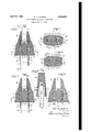
Fig. 1 is a longitudinal `sectional view taken on the line l-l of Fig. 2 and showing the parts in the positions which they assume when the locking arms are in position to interlock the electrical connector with a plug receptacle or the like;
Fig. 2 is a transverse sectional view taken on the line 2-2 of Fig. 1;
Fig. 3 is a longitudinal sectional view taken onV the line 3--3 of Fig. 1;
Fig. 4 is a longitudinal sectional view similar to Fig. 1 but showing the locking arms retracted Fig. 5 is a transverse sectional view similar to Fig. 1 but taken on the line 5--5 of Fig. 4; and
Fig. 6 is a sectionalperspective View of the body taken on the central flatwise plane thereof.
The particular self-locking electrical connector herein chosen for purposes of illustrating a preferred embodiment of the present invention, is in the form of a double-pronged plug unit of the type adapted to be thrust into and pulled out of connection with yan electrical supply receptacle or outlet, which plug unit comprises a, resilient body generally designated by the reference character l 0, two corresponding or like contact prongs or members, each generally designated by the reference character Il, and two corresponding flexible locking arms or members, each generallyv designated by the reference character I2. As shown, the plug body is generally oblong in crosssection, with a pair of opposed relatively broad lateral faces Illa and a pair of opposed narrower lateral faces thereto.
I 0b substantially perpendicular The body I0 may be formed of any suitable natural rubber or synthetic resins. Some of the resilient insulating materials suitable for the present purposes are:
(1) vulcanized copolymers of styrene and butadiene,
(2) vulcanized copolymers of polyisobutylene and isoprene or butadiene,
(3) vulcanized polychloroprene,
(4) vulcanized copolymers of butadiene and acrylonitrile,
(5) vulcanized organic polysulde,
(6) Plasticized vinyl chloride polymers, and Y (7) Plasticized vinyl chloride-vinyl acetate Y copolymers.
Extending axially in the inner or cord end of the body II! is a passage I3 into which is fitted the end portion of a multiple-conductor cable or cord I4 having, in the present instance, two sets of individually insulated conductors I5-I5 each preferably formed of a group of ne strands of copper or the like.
Formed in the resilient body I0 and opening through its outer or prong end I6, is a pair of like prong-anchoring recesses or cavities II-I'I which extend longitudinally in the said body in substantial parallelism with each other and in spaced-apart relation on opposite sides of the plug axis. Each of the said recesses is of slotlike form in cross'section with its major crosssectional transverse dimension extending in a direction substantially perpendicular with respect to a line drawn between the tvvol recesses. The two said laterally spaced apart recesses I'I-I'I serve, in effect, to divide the one-piece resilient body Il) into three longitudinally extending sections or arms which are aligned, in normally spaced-apart relation, in the direction of the major cross-sectional dimension of the plug body, namelypa central spacing-arm or section I8 extending substantially in an -axial direc-tion away from the cable I4, parallel to and situated between those portions of the contact prongs or blades which are within the plug body IIJ; together with two outer flexible releasing arms or end sections ISI-I9 which are movable toward and away from each other and toward and away from the spacing arm I8 in a. manner that will hereinafter appear. As compared to the flexible outer lock-controlling or releasing arms I9, the central prong-spacing arm is seen from the drawings to be relatively massive and unyielding.
Respectively located in the recesses I'I-I'I in the body I9 are the inner portions of the conf tact prongs II-II before referred to and which contact prongs project at their outer ends fromV and beyond the outer end I 6 of the said body I0. Each of the said contact prongs may be conveniently formed up of spring brass or other suitable resilient metal, and in the instance shown is channel-like in cross-section, being formed with parallel side flanges 20-20 which are spaced from each other a distance sufficient to freely accommodate between them the companion (J1-'associated locking-arm I2. The said flexible locking a-rm is preferably pretensioned or biased so as to normally tend to stand in spaced relationship outwardly from its companion contact blade II as is especially well shown in Figs. 1 and 2.
Preferably and as shown, each contact prong I I and its comp-anion locking arm I2 are integrally united with each other at their Yrespective inner or upper ends.A Adjacent its junction with the companionrcontact prong II, each locking arm I2 is preferablyiiattened tightly against the adjacent face of the said contact prong as shown, and in `this area of contact, both the contact' prong II and its companion locking arm I2 are jointly pierced transversely to provide an aperture through which the bared end of the adjacent one of the conductors I5 may be passed and soldered or otherwise rigidly connected to the unit comprising the two members I I and I2.
As thus constructed and arranged, each contact prong I I is mounted against the inner wall of the particular recess I'I in which it is located and is preferably firmly coupled to the said wall in any suitablemanner such, for instance, as by being provided with an offsetting coupling finger 2| embedded in the resilient material from which the body I0 is for-med. Each locking arm I2 is located against the outer wall of the particular recess I l in which it is mounted and is preferably firmly coupled tosuch wall in any suitable manner such, for instance, as by striking therefrom a coupling nger 22 which is embedded in theresilient material from which the body IB is made. At its lower end, each resilient locking arm I2 has -1 detent or latching provision, said end being in this instance bent outwardly away from the com-V #j of the present invention is the secure attach-l ment of a given contact prong II to the Vinner wall of the particular recess I1 in which it is mounted and the attachment of the companion.
locking arm I2 to the outer wall of the said recess, whereby the tension of the resilient body Iii will serve to yieldingly hold agiven locking arm I 2 away from its companioncontact prong II, as is shown in Figs. 1 and 2. In addition to or inV lieu of the attachment provided by the coupling fingers 2l and 22, the contact prongs' II and the locking arms I2 may be secured to the respective walls of a given recess II by being suitably adhered to the material from which the body I isV formed, in a manner well known in the art.
Suitable cements foreffecting the adhering just above referred to are numerous, but the fol' lowing may be mentioned by wayV of example:
(1) Cements made from solutions or dispersions of rubber conversion products such as are produced by the action of sulfuric acid or benzene-sulfonie acid on natural crude rubber.
(2) Alkyd resin cements,
(3)V Polychloroprene cements, and
(4) Cements made of natural or synthetic rubber compositions containing vulcanizing agents.
It will be noted by reference to Figs. 2 and 3, in parti-cular, that each longitudinal recess I'I has its major transverse dimension in a direction substantially perpendicular to a line vdrawn between the two said recesses, and this major transverse dimension is greater than the similar transverse dimension of both the contact prong II and companion locking arms I I 2 mounted therein. This relationship, in effect, causes the respective opposite edges of each of the said recesses to constitute longitudinal clearance channels 2li-2li. As thus proportioned, each releasing arm I9 is integrally connected to the central spacing arm of the body I by means of relatively thin iiexible and compressible connecting webs 25-25. Y
Preferably, the body I6 is injection-molded in one piece around the elements II, I2, I4 and I5, during which molding operation suitable removablellers .(i. e. core material) lmay be placed acaaovo 5. between a given contact prong `Il and its "complemental locking armIZ to exclude the resilient material from therebetween, whereby to maintain them normally spaced apart to the extent indicated in Figs. l and 2, and to laterally extend the cross-sectional dimensions of the recesses Il `to form the clearance channels 24 and the flexible connecting webs 25.
The self-locking electrical connector above described is adapted to have its contact prongs II-Il inserted together with the companion locking arms i2-l2) through the usual slots or apertures in another electrical connector of any suitable character and commonlyknownasaplug receptacle. Such plug receptacles are frequently formed interiorly with abutments with which the respective locking iingers 23-23 may engage to releasably couple or interlock the connector of the present invention with such plug receptacle, al1 in a manner well understood in the art.
To effect the insertion of the contact prong H-ll and the companion locking arms I2-I2 into the usual slots or apertures in a plug receptacle or the like, the body I may be squeezed by finger pressure applied simultaneously to the respective outer faces of the flexible releasing arms IQ-IS of the said body. The described squeezing will cause the said releasing arms |9-I 9 to ex inwardly toward each other, thereby, in turn, inwardly flexing the locking arms lZ-lZ toward their respective contact prongs Il-Ii into substantially the positions in which the parts are shown in Figs. 4 and 5. It will be noted that when the body I is squeezed as just described, the locking lingers 23-23 of the respective locking arms I2-I 2 will be retired close to their respective contact prongs II-ll, as is especially well indicated in Fig. 4, without materially altering the predetermined spacing between the said contact prongs iI-I l.
Upon the squeezing pressure above referred to being released, the locking arms |2-I2 will be restored to substantially the positions in which they are shown in Figs. 1 and 2, under the combined urge of the locking arms themselves and of the resilient material of the body I0, so that the locking fingers 23-23 will be in position to engage with any suitable abutments within a plug receptacle to interlock the device of the present invention with the said plug receptacle.
Where, as is often the case, the plug receptacle is provided with suitably formed guide surfaces sloped to the prong receiving apertures, entry of the prong-and-locking-arm units of the present novel plug connector construction into said apertures may obviously be effected by a simple thrusting movement, without applying the described squeezing pressure to the end sections I9 of the plug connector.
To effect the disconnection of the electrical connector of the present invention from a plug receptacle or the like, the squeezing action above referred to may be repeated and the entire connector withdrawn from the plug receptacle before the squeezing pressure referred to is relaxed.
During the squeezing of the body I0, as above described, the locking arms IZ-l 2 move inwardly as described, without causing the material displacement of the contact prongs II--II toward each other, which thus remain substantially in their predetermined spaced-apart relationships, whereby they may be readily entered into and removed from a plug receptacle or the like.
During the described squeezing of the body l0 to effect the retirement of the locking arms 421-123 the connecting websf 25 of the "body 40s. provide, in conjunction with the clearancev chan-.a
disturbing the g spacings of the contactprongsj The invention may be carried out in other epee cific Ways than those herein set forth withouty departing` from the spirit andessential characteristics of the invention, andthe present em-V bodiments are, therefore, to be considered in `all=` respects as illustrative and not restrictive, and all changes coming within the meaning and equivalency range of the appended claims are intended to be embraced therein.
I claim:
1. A self-locking electrical connector plug comprising a plug body of resilient insulating material having a cord end and a prong end and a pair of opposed relatively broad lateral faces, a pair of contact prongs anchored Within said body and projecting from said prong end in substantially fixed parallel relation to each other, the inner portions of the prongs being disposed in spaced parallel slots formed within said body and dividing it longitudinally at this locality into a central prong supporting and spacing section and two end sections, each of said slots being substantially wider than the thickness of the prong disposed therein and extending beyond both edges of said prong transversely of said body toward the broad lateral faces thereof, whereby to give said body maximum flexibility along the slot ends, said contact prongs being firmly secured within their respective slots to said central supporting and spacing section; a pair of locking arms each firmly secured within one of said slots to the adjacent end body section in spaced relation to the contact prong secured to said section, each said arm projecting outwardly from the open end of the slot and having detent provision for locking engagement with cooperating detent provision in a plug receptacle into which the plug is adapted to be thrust, said locking arms being movable inwardly to clear the receptacle detent provision by compressing said end sections toward said central section against the resiliency of said body material; and means connecting lead wires to the inner ends of the prongs.
2. A self-locking electrical connector as defined in claim 1, wherein each of said contact prongs is provided with side flanges adapted and arranged to permit entry between them of the respective locking arm associated with such prong.
3. A self-locking electrical connector as dened in claim 2, wherein said contact prongs and locking arms are formed of suitable resilient metal, and the locking arms are so biased that each normally tends to maintain the spaced relationship between it and the contact prong with which it is associated.
4. A self-locking electrical connector as dened in claim 3, wherein each said contact prong and its associated locking arm are united with each other at their ends located within the plug body, and to those junctions are secured the conductor terminals of a multiple conductor cord of which the end portion enters said plug body.
5. A self-locking electrical connector as deiined in claim 4, wherein said plug body is composed of resilient insulating material molded in 7A one piece about the'other elements specied in said claim.
6. A self-locking electrical conductor as defined in `claim 5, wherein said cavities, in Which are located the units each comprising acontact prong lamd an associated locking arm, extend laterally beyond both edges of both said units to such 'a distanceas to provide that the resilient connection of each lock-controlling section of the plug body is constituted by relatively thin, exible and compressible webs of said insulating material.
CARL H. JUDISCH.
"References Cited in the. le o1' this patent UNITED STATES PA'IENTS Number
Priority Applications (1)
| Application Number | Priority Date | Filing Date | Title |
|---|---|---|---|
| US118025A US2636070A (en) | 1949-09-27 | 1949-09-27 | Self-locking electrical connector |
Applications Claiming Priority (1)
| Application Number | Priority Date | Filing Date | Title |
|---|---|---|---|
| US118025A US2636070A (en) | 1949-09-27 | 1949-09-27 | Self-locking electrical connector |
Publications (1)
| Publication Number | Publication Date |
|---|---|
| US2636070A true US2636070A (en) | 1953-04-21 |
Family
ID=22376088
Family Applications (1)
| Application Number | Title | Priority Date | Filing Date |
|---|---|---|---|
| US118025A Expired - Lifetime US2636070A (en) | 1949-09-27 | 1949-09-27 | Self-locking electrical connector |
Country Status (1)
| Country | Link |
|---|---|
| US (1) | US2636070A (en) |
Cited By (3)
| Publication number | Priority date | Publication date | Assignee | Title |
|---|---|---|---|---|
| US3249909A (en) * | 1963-11-15 | 1966-05-03 | Electrolux Corp | Strain-relieved electrical cord device |
| US6071141A (en) * | 1998-05-14 | 2000-06-06 | Berg Technology, Inc. | Connector latches |
| US20100000359A1 (en) * | 2008-07-01 | 2010-01-07 | Kops William R | Shifter with one-touch assembly |
Citations (4)
| Publication number | Priority date | Publication date | Assignee | Title |
|---|---|---|---|---|
| US1957778A (en) * | 1932-07-25 | 1934-05-08 | Jr Albert F Hopkins | Separable plug |
| US2235020A (en) * | 1938-08-13 | 1941-03-18 | David C Jones | Electrical connector |
| US2498743A (en) * | 1946-12-28 | 1950-02-28 | Theriault Lucien | Self-locking electrical connector |
| US2521298A (en) * | 1947-07-08 | 1950-09-05 | Ludwig Louis | Electric plug |
-
1949
- 1949-09-27 US US118025A patent/US2636070A/en not_active Expired - Lifetime
Patent Citations (4)
| Publication number | Priority date | Publication date | Assignee | Title |
|---|---|---|---|---|
| US1957778A (en) * | 1932-07-25 | 1934-05-08 | Jr Albert F Hopkins | Separable plug |
| US2235020A (en) * | 1938-08-13 | 1941-03-18 | David C Jones | Electrical connector |
| US2498743A (en) * | 1946-12-28 | 1950-02-28 | Theriault Lucien | Self-locking electrical connector |
| US2521298A (en) * | 1947-07-08 | 1950-09-05 | Ludwig Louis | Electric plug |
Cited By (4)
| Publication number | Priority date | Publication date | Assignee | Title |
|---|---|---|---|---|
| US3249909A (en) * | 1963-11-15 | 1966-05-03 | Electrolux Corp | Strain-relieved electrical cord device |
| US6071141A (en) * | 1998-05-14 | 2000-06-06 | Berg Technology, Inc. | Connector latches |
| US20100000359A1 (en) * | 2008-07-01 | 2010-01-07 | Kops William R | Shifter with one-touch assembly |
| US8424409B2 (en) | 2008-07-01 | 2013-04-23 | Ghsp, Inc. | Shifter with one-touch assembly |
Similar Documents
| Publication | Publication Date | Title |
|---|---|---|
| US3181974A (en) | Releasable battery clip | |
| US2673968A (en) | Self-piercing electrical connector plug | |
| US2744244A (en) | Electrical connector | |
| US2974186A (en) | Strain relief bushing | |
| US3178674A (en) | Electrical connector | |
| US1918126A (en) | Electrical connecter | |
| US2276557A (en) | Electric connector | |
| US2361721A (en) | Electric circuit molding | |
| US2497523A (en) | Electrical cable disconnect | |
| US4125312A (en) | Connector for electrical apparatus | |
| US3031640A (en) | Spring clip snap-in contact | |
| US2966651A (en) | Three to two-wire plug adapter with grounding pigtail | |
| US3335394A (en) | Appliance connector | |
| US2636070A (en) | Self-locking electrical connector | |
| US2924806A (en) | Electrical locking connector | |
| US5634826A (en) | Electrical connector | |
| US2810115A (en) | Connectors for lamp cords | |
| US2713154A (en) | Electrical connector | |
| US2495206A (en) | Electrical plug | |
| US2192737A (en) | Plug cap | |
| US3274531A (en) | Electrical connector | |
| US2704832A (en) | Multiple cord plug receptacle | |
| US2597262A (en) | Electrical connection plug | |
| US2429278A (en) | Electrical connector plug | |
| US2730685A (en) | Plug-and-socket connector |