US2629376A - Injection syringe - Google Patents
Injection syringe Download PDFInfo
- Publication number
- US2629376A US2629376A US104922A US10492249A US2629376A US 2629376 A US2629376 A US 2629376A US 104922 A US104922 A US 104922A US 10492249 A US10492249 A US 10492249A US 2629376 A US2629376 A US 2629376A
- Authority
- US
- United States
- Prior art keywords
- groove
- tube
- annular
- piston
- cylindrical
- Prior art date
- Legal status (The legal status is an assumption and is not a legal conclusion. Google has not performed a legal analysis and makes no representation as to the accuracy of the status listed.)
- Expired - Lifetime
Links
- 238000002347 injection Methods 0.000 title description 30
- 239000007924 injection Substances 0.000 title description 30
- 238000010276 construction Methods 0.000 description 3
- 229920003023 plastic Polymers 0.000 description 3
- 239000004033 plastic Substances 0.000 description 3
- 230000006835 compression Effects 0.000 description 2
- 238000007906 compression Methods 0.000 description 2
- 238000004519 manufacturing process Methods 0.000 description 2
- SLZWEMYSYKOWCG-UHFFFAOYSA-N Etacelasil Chemical compound COCCO[Si](CCCl)(OCCOC)OCCOC SLZWEMYSYKOWCG-UHFFFAOYSA-N 0.000 description 1
- 230000006978 adaptation Effects 0.000 description 1
- 229940000425 combination drug Drugs 0.000 description 1
- 230000003247 decreasing effect Effects 0.000 description 1
- 239000011521 glass Substances 0.000 description 1
- 239000000463 material Substances 0.000 description 1
- 238000000034 method Methods 0.000 description 1
- 238000012986 modification Methods 0.000 description 1
- 230000004048 modification Effects 0.000 description 1
- 230000002093 peripheral effect Effects 0.000 description 1
- 239000012858 resilient material Substances 0.000 description 1
- 230000000284 resting effect Effects 0.000 description 1
Images
Classifications
-
- A—HUMAN NECESSITIES
- A61—MEDICAL OR VETERINARY SCIENCE; HYGIENE
- A61M—DEVICES FOR INTRODUCING MEDIA INTO, OR ONTO, THE BODY; DEVICES FOR TRANSDUCING BODY MEDIA OR FOR TAKING MEDIA FROM THE BODY; DEVICES FOR PRODUCING OR ENDING SLEEP OR STUPOR
- A61M5/00—Devices for bringing media into the body in a subcutaneous, intra-vascular or intramuscular way; Accessories therefor, e.g. filling or cleaning devices, arm-rests
- A61M5/178—Syringes
- A61M5/31—Details
- A61M5/315—Pistons; Piston-rods; Guiding, blocking or restricting the movement of the rod or piston; Appliances on the rod for facilitating dosing ; Dosing mechanisms
- A61M5/31511—Piston or piston-rod constructions, e.g. connection of piston with piston-rod
- A61M5/31513—Piston constructions to improve sealing or sliding
Definitions
- the present invention relates to injection syringes.
- One of the objects of the present invention is to provide an injection syringe which may be manufactured at an extremely low cost and by mass production methods.
- a further object of the present invention is to provide an injection syringe of the above type which will faithfully provide the desired tightness between the cylinder and piston.
- the present invention mainly consists of providing an injection syringe having a piston formed at its inner, free end portion with an annular groove in which an elastic ring is located, this ring being capable of slidably moving into and out of the groove and having, in its unstressed condition, an outer diameter larger than the inner diameter of the cylinder so that the desired tightness is assured by means of this ring.
- Fig. 1 is a fragmentary, side sectional view of one possible injection syringe constructed in accordance with the present invention
- Fig, 2 is a fragmentary, side sectional view ci a second possible construction of an injection syringe made in accordance with the present invention
- Fig. 3 is a'fragmentary, side sectional View of a third possible injection syringe constructed in accordance with the present invention.
- Fig. 4 is a fragmentary, side sectional view of a fourth possible injection syringe constructed in accordance with the present invention
- Fig. 5 is a fragmentary, side sectional view of a fth possible. injection syringe constructed in accordance with the present invention.
- the structures shown in the several figures comprise three essential parts, namely, a cylinder made of glass or plastics or any other suitable material, a piston provided with an annular groove adjacent its left end, as viewed in the drawings, and a resilient ring located within this groove of the piston and in its unstressed condition having an outer diameter slightly larger than the inside diameter of the cylinder so that an outer peripheral portion of the ring protrudes from the piston and, by the springy action inherent in the resilient material of the ring, bears constantly and uniformly against the inner wall of the cylinder.
- This ring which is freely movable into and out of the groove of the piston yieldingly accommodates itself to the irregularities on the inner wall of the cylinder so as to produce, irrespective of such irregularities, the desired tightness.
- the open end of the cylinder (not shown) is slightly divergent so as to facilitate the introduction of the piston with the elastic ring thereon into the cylinder, this ring gradually adapting itself to the slightly decreasing diameter of the cylinder as the piston moves into the latter, and this arrangement is very convenient when it is desired to replace worn rings.
- the groove of piston P2 is not as deep as that of the groove of piston P1, and the elastic ring A2 has the crosssection of a. circle, this ring A2 also having its inner annular surface spaced from the bottom surface of the groove in the piston P2 so as to be movable toward this bottom surface upon compression of the ring A2 by the wall of the cylinder C2.
- Figs. 3-5 differ from those of Figs. 1 and 2 in that the elastic rings bear against the bottom surface of the groove in the piston.
- the elastic ring A3 has a polygonal crosssection which provides a cylindrical outer surface to bear against the inner wall of cylinder C3 and which provides the meeting edge between two oppositely inclined annular inner portions of the ring A3 to bear against the bottom cylindrical surface of the groove in the piston P3.
- Fig. 4 is similar to that of Fig. 3 except that the elastic ring A4 is provided with an inner, annular, at portion having an inner cylindrical surface located against the bottom cylindrical wall of the groove of piston P4. As is clearly apparent from Fig. e, this inner annular portion of ring Ai is narrower than the width of the groove of piston P4 so that free spaces are provided into which the ring A4 may be compressed by the inner wall of cylinder C4.
- the elastic ring A5 takes the forni of a hollow, annular tube resting with its inner' annular surface against the bottom cylindrical surface of the groove in the piston P5.
- the ring A5 is yieldably compressible by the inner wall of C5 by reason of the air space within the ring A5 as well as by reason of the annular spaces located between the ring A5 and the bottom surface of the groove in the piston P5, as is clearly shown in Fig. 5.
- the rings Ai, A3, and Ai each have inner and outer annular portions located apart from each other ⁇ by a distance greater than the distance between the side walls of the grooves, and the latter have a depth greater than their width.
- An injection syringe comprising in combination, a tube having an inner, substantially cylindrical surface; a piston having an end portion thereof located within said tube and being formed with an annular groove having a cylindrical bottom surface and two opposite, annular, fixed side walls normal to said bottom surface and extending toward said cylindrical surface of saidtube;
- An injection syringe comprising in combination, a tube having an inner, substantially cylindrical surface; a piston having an end portion thereof located within said tube and being formed with an annular groove having a cylindrical bottom surface and two opposite, annular, fixed side walls normal to said bottom surface and extending toward said cylindrical surface of said tube; and resilient ring means loosely mounted in said groove and, in its uncompressed state, having an outer annular portion of a greater diameter than the diameter of said inner surface of said tube, so that said ring means is compressed by the latter, and said ring means having an inner annular portion spaced from said cylindrical bottom surface of said groove, the distance between said inner and outer annular portions of said ring means being greater than the distance between said side walls of said groove.
- An injection syringe comprising in combination, a tube having an inner, substantially cylindrcal surface; a piston having an end portion thereof located within said tube and being formed within an annular groove having a cylindrical bottom surface and two opposite, annular, side walls integral with said piston, normal to said bottom surface and extending toward said cylindrical surface of said tube; and resilient ring means loosely mounted in said groove and, in its uncompressed state, having an outer annular portion of a greater diameter than the diameter of said inner surface of said tube, so that said ring means is compressed by the latter, and said ring means having an inner annular portion spaced from said cylindrical bottom surface of said groove.
- An injection syringe comprising in combination, a tube having an inner. substantially cylindrical surface; a piston having an end portion thereof located within said tube and being formed Awith an annular groove having,v a cylindricalA bottom. surface and two opposite, annular, side walls integral with. said piston, normal to said bottom surface and extending toward said cylindrical surface of said tube, said groove having a depth greater than its width; and ⁇ resilient ring means loosely mounted in said groove and, in its uncompressed state, having an outer annular portion of a greater diameter than the diameter of said inner surface of said tube, so that said ring means is compressed by the latter, andr said ring means having an inner' annular portion spaced from said cylindrical bottom surface of said groove.
- An injection syringe comprisingin combination, a tube having an inner, substantially cylindrical surface; a piston having an end portion thereof located within said tube and being formed with an annular groove having a cylindrical' bottom surface and two opposite, annular fixed side walls normal to said. bottom surface and extending toward said cylindrical surface of said tube; and resilient ring means loosely mounted in said groove and, in its uncompressed state, having an outer annular portion of a greater diameter than the diameter of said inner surfacev of saidtube, so that said ring means ⁇ is ⁇ compressed by the latter, andy said ring means having an inner periphery spaced at all parts thereof from said cylindrical bottom surface of said groove.
- An injection syringe comprising in combination, a tube having an inner, substantially cylindrical surface; a piston having an end portion thereof located within said tube and being formed with an annular groove having a cylindrical bottom surface and two opposite, annular, fixed side walls normal to said bottom surface and extending toward said cylindrical surface of said tube; and resilient ring means loosely mounted in said groove and, in its uncompressed state, having an outer annular portion of a greater diameter than the diameter of said inner surface of said tube, so that said ring means is compressed by the latter, and said ring means having an inner periphery having opposite side edge portions spaced from said cylindrical bottom surface of said groove.
- An injection syringe comprising in combination, a tube havingl an inner, substantially cylindrical surface; a piston having an end portion thereof located ywithin said tube and being formed with an annular groove having a cylindrical bottom surface and two opposite, annular, xed side walls normal to said bottom surface and extending toward said cylindrical surface of said tube; and resilient ring means loosely mounted in said groove and, in its uncompressed state, having an outer annular portion of a greater diameter than the diameter of said inner surface of said tube, so that said ring means is compressed by the latter, and said ring means having an inner periphery having opposite side edge portions spaced from said cylindrical bottom surface of said groove and a central portion contacting the latter.
- An injection syringe comprising in comb-ination, a tube having an inner, substantially cylindrical surface; a piston having an end portion thereof located within said tube and being formed with an annular groove having a cylindrical bottom surface and two opposite, annular fixed side walls normal to said bottom surface and extending toward said cylindrical surface of said tube; and resilient ring means loosely mounted in said groove and, in its uncompressed state, having an outer annular portion of a greater diameter than the diameter of said inner surface of said tube, so that said ring means is compressed by the latter, and said ring means having an inner cylindrical periphery spaced at all parts thereof from said cylindrical bottom surface of said groove.
- An injection syringe comprising in combination, a tube having an inner, substantially cylindrical surface; a piston having an end portion thereof located within said tube and being formed with an annular groove having a cylindrical bottom surface and two opposite, annular, fixed side walls normal to said bottom surface and extending toward said cylindrical surface of said tube; and resilient ring means loosely mounted in said groove, and, in its uncompressed state, having an outer annular portion of a greater diameter than the diameter of said inner surface of said tube, so that said ring means is compressed by the latter, and said ring means having an inner V- shaped periphery having opposite side edge portions spaced from said cylindrical bottom surface of said groove.
- An injection syringe comprising in combination, a tube having an inner, substantially cylindrical surface; a piston having an end portion thereof located within said tube and being formed with an annular groove having a cylindrical bottom surface and two opposite, annular, fixed side walls normal to said bottom surface and extending toward said cylindrical surface of said tube; and resilient ring means loosely mounted in said groove, and, in its uncompressed state, having an outer annular portion of a greater diameter than the diameter of said inner surface of said tube, so that said ring means is compressed by the latter, and said ring means having an inner V-shaped periphery having opposite side edge portions spaced from said cylindrical bottom surface of said groove and a central portion contacting the latter.
- An injection syringe comprising in combination, a tube having an inner, substantially cylindrica1 surface; a piston having an end portion thereof located within said tube and being formed with an annular groove having a cylindrical bottom surface and two opposite, annular, xed side walls normal to said bottom surface and extending toward said cylindrical surface of said tube; and resilient ring means of circular cross-section loosely mounted in said groove and, in its uncompressed state, having an outer annular portion of a greater diameter than the diameter of said inner surface of said tube, so that said ring means is compressed by the latter, and said ring means having an inner periphery having opposite side edge portions spaced from said cylindrical bottom surface of said groove.
- An injection syringe comprising in combination, a tube having an inner, substantially cylindrical surface; a piston having an end portion thereof located within said tube and being formed with an annular groove having a cylindrical bottom surface and two opposite, annular, fixed side walls normal to said bottom surface and extending toward said cylindrica1 surface of said tube; and resilient, hollow ring means of circular crosssection loosely mounted in said groove and, in its uncompressed state, having an outer annular portion of a greater diameter than the diameter of said inner surface of said tube, so that said ring means is compressed by the latter, and said ring means having an inner periphery having opposite side edge portions spaced from said cylindrical bottom surface of said groove.
- An injection syringe comprising in combination, a tube having an inner, substantially cylindrical surface; a piston having an end portion thereof located within said tube and being formed with an annular groove having a cylindrical bottom surface and two opposite, annular, fixed side walls normal to said bottom surface and extending toward said cylindrical surface of said tube; and resilient ring means loosely mounted in said groove and, in its uncompressed state, having an outer annular portion of a greater diameter than the diameter of said inner surface of said tube, so that said ring means is compressed by the latter, and said ring means having a pair of inner side annular portions spaced from said cylindrical bottom surface of said groove and a central annular portion contacting said bottom surface of said groove and having opposite side faces spaced from said side walls of said groove.
- An injection syringe comprising in combination, a plastic tube having an inner, substantially cylindrical surface; a plastic piston having an end portion thereof located within said tube and being formed with an annular groove having a cylindrical bottom surface and two opposite, annular, fixed side walls normal to said bottom surface and extending toward said cylindrical surface of said tube; and resilient ring means loosely mounted in said groove and, in its uncomvpressed state, having fan outer annular portion of a .greater diameter than the diameter of said inner surface of said tube, ⁇ so that said ring means is compressed by the latterq and said ring means having an inner annular portion spaced from said cylindrical bottom surface of said groove.
Landscapes
- Health & Medical Sciences (AREA)
- Vascular Medicine (AREA)
- Engineering & Computer Science (AREA)
- Anesthesiology (AREA)
- Biomedical Technology (AREA)
- Heart & Thoracic Surgery (AREA)
- Hematology (AREA)
- Life Sciences & Earth Sciences (AREA)
- Animal Behavior & Ethology (AREA)
- General Health & Medical Sciences (AREA)
- Public Health (AREA)
- Veterinary Medicine (AREA)
- Infusion, Injection, And Reservoir Apparatuses (AREA)
Description
Feb. 24, 1953 P. GALLICE ET AL. 2,629,376
INJECTION SYRINGE Filed July l5, 1949 u Ip? C3 Patented Feb. 24, 1953 UNITED STATES PATENT OFFICE INJECTION SYRINGE of France Application July 15, 1949, Serial No. 104,922 In France July 22, 1948 (Cl. 12S-218) 14 Claims.
The present invention relates to injection syringes.
Known injection syringes are fairly expensive and difficult to manufacture because they must .be made with great precision to provide an accurate fit between the outside of the piston and the inside of the cylinder.
One of the objects of the present invention is to provide an injection syringe which may be manufactured at an extremely low cost and by mass production methods.
A further object of the present invention is to provide an injection syringe of the above type which will faithfully provide the desired tightness between the cylinder and piston.
With these objects in view the present invention mainly consists of providing an injection syringe having a piston formed at its inner, free end portion with an annular groove in which an elastic ring is located, this ring being capable of slidably moving into and out of the groove and having, in its unstressed condition, an outer diameter larger than the inner diameter of the cylinder so that the desired tightness is assured by means of this ring.
The novel features which are considered as characteristic for the invention are set forth in particular in the appended claims. The invention itself, however, both as toI its construction and its method of operation, together with additional objects and advantages thereof, will be best understood from the following description of specific embodiments when read in connection with the accompanying drawings, in which:
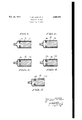
Fig. 1 is a fragmentary, side sectional view of one possible injection syringe constructed in accordance with the present invention;
Fig, 2 is a fragmentary, side sectional view ci a second possible construction of an injection syringe made in accordance with the present invention;
Fig. 3 is a'fragmentary, side sectional View of a third possible injection syringe constructed in accordance with the present invention;
Fig. 4 is a fragmentary, side sectional view of a fourth possible injection syringe constructed in accordance with the present invention; and Fig. 5 is a fragmentary, side sectional view of a fth possible. injection syringe constructed in accordance with the present invention.
. Referring. now tothe drawings, the structures shown in the several figures comprise three essential parts, namely, a cylinder made of glass or plastics or any other suitable material, a piston provided with an annular groove adjacent its left end, as viewed in the drawings, and a resilient ring located within this groove of the piston and in its unstressed condition having an outer diameter slightly larger than the inside diameter of the cylinder so that an outer peripheral portion of the ring protrudes from the piston and, by the springy action inherent in the resilient material of the ring, bears constantly and uniformly against the inner wall of the cylinder. This ring which is freely movable into and out of the groove of the piston yieldingly accommodates itself to the irregularities on the inner wall of the cylinder so as to produce, irrespective of such irregularities, the desired tightness.
The open end of the cylinder (not shown) is slightly divergent so as to facilitate the introduction of the piston with the elastic ring thereon into the cylinder, this ring gradually adapting itself to the slightly decreasing diameter of the cylinder as the piston moves into the latter, and this arrangement is very convenient when it is desired to replace worn rings.
The above described features are common to all embodiments of the invention. Referring specifically to the several embodiments, it is seen that in the structure illustrated in Fig. 1, the piston P1 iS located in the cylinder C1 with a considerable clearance and supports, for slidable movement into and out of its groove, an elastic ring A1 which has a cylindrical inner annular surface and an outer annular portion having the cross-section of a semi-circle. It will be noted that the inner cylindrical surface of ring A1 is spaced from the bottom cylindrical surface of the groove in piston P1 so that the ring A1 will move toward this bottom surface of the groove upon compression by the cylinder wall.
In the embodiment of Fig. 2, the groove of piston P2, is not as deep as that of the groove of piston P1, and the elastic ring A2 has the crosssection of a. circle, this ring A2 also having its inner annular surface spaced from the bottom surface of the groove in the piston P2 so as to be movable toward this bottom surface upon compression of the ring A2 by the wall of the cylinder C2.
The embodiments of Figs. 3-5 differ from those of Figs. 1 and 2 in that the elastic rings bear against the bottom surface of the groove in the piston. Thus, in the embodiment of Fig. 3 it is seen that the elastic ring A3 has a polygonal crosssection which provides a cylindrical outer surface to bear against the inner wall of cylinder C3 and which provides the meeting edge between two oppositely inclined annular inner portions of the ring A3 to bear against the bottom cylindrical surface of the groove in the piston P3. There are thus provided two annular free spaces next to the bottom surface of the groove of piston Ps into which the ring A3 may move when the latter is compressed by the wall of cylinder of Ca.
The embodiment of Fig. 4 is similar to that of Fig. 3 except that the elastic ring A4 is provided with an inner, annular, at portion having an inner cylindrical surface located against the bottom cylindrical wall of the groove of piston P4. As is clearly apparent from Fig. e, this inner annular portion of ring Ai is narrower than the width of the groove of piston P4 so that free spaces are provided into which the ring A4 may be compressed by the inner wall of cylinder C4.
In the embodiment of Fig. 5, the elastic ring A5 takes the forni of a hollow, annular tube resting with its inner' annular surface against the bottom cylindrical surface of the groove in the piston P5. Thus, with the construction shown in Fig. 5, the ring A5 is yieldably compressible by the inner wall of C5 by reason of the air space within the ring A5 as well as by reason of the annular spaces located between the ring A5 and the bottom surface of the groove in the piston P5, as is clearly shown in Fig. 5.
In the embodiments of Figs. l, 3, and 4, the rings Ai, A3, and Ai each have inner and outer annular portions located apart from each other` by a distance greater than the distance between the side walls of the grooves, and the latter have a depth greater than their width.
It will be understood that each of the elements described above, or two or more. together, may alsol find a useful application in other types of injection syringes differing from the types described above.
While the invention has been illustrated and described as embodied in injection syringes having an elastic piston ring bearing against the inner wall of the cylinder of the injection syringe, it is not intended to be limited to the details shown, since various modifications and structural changes may be made without departing in any way from the spirit of the present invention.
Without further analysis, the foregoing will so fully reveal the gist of the present invention that others can by applying current knowledge readily adapt it for various applications without omitting' features that, from the standpoint of prior art, fairly constitute essential characteristics 0f the generic or specific aspects of this invention and, therefore, such adaptations should and are intended to be comprehended within the meaning and range of equivalence of the following claims.
What is claimed as new and desired to be secured by Letters Patent is:
l. An injection syringe, comprising in combination, a tube having an inner, substantially cylindrical surface; a piston having an end portion thereof located within said tube and being formed with an annular groove having a cylindrical bottom surface and two opposite, annular, fixed side walls normal to said bottom surface and extending toward said cylindrical surface of saidtube;
and resilient ring means loosely mounted in said groove and, in its uncompressed state, having an outer annular portion of a greater diameter than the diameter of said inner surface of said tube, so that said ring means is compressed by the latter, and said ring means having an inner annular portion spaced from said cylindrical bottom surface of said groove.
2. An injection syringe, comprising in combination, a tube having an inner, substantially cylindrical surface; a piston having an end portion thereof located within said tube and being formed with an annular groove having a cylindrical bottom surface and two opposite, annular, fixed side walls normal to said bottom surface and extending toward said cylindrical surface of said tube; and resilient ring means loosely mounted in said groove and, in its uncompressed state, having an outer annular portion of a greater diameter than the diameter of said inner surface of said tube, so that said ring means is compressed by the latter, and said ring means having an inner annular portion spaced from said cylindrical bottom surface of said groove, the distance between said inner and outer annular portions of said ring means being greater than the distance between said side walls of said groove.
3. An injection syringe, comprising in combination, a tube having an inner, substantially cylindrcal surface; a piston having an end portion thereof located within said tube and being formed within an annular groove having a cylindrical bottom surface and two opposite, annular, side walls integral with said piston, normal to said bottom surface and extending toward said cylindrical surface of said tube; and resilient ring means loosely mounted in said groove and, in its uncompressed state, having an outer annular portion of a greater diameter than the diameter of said inner surface of said tube, so that said ring means is compressed by the latter, and said ring means having an inner annular portion spaced from said cylindrical bottom surface of said groove.
4. An injection syringe, comprising in combination, a tube having an inner. substantially cylindrical surface; a piston having an end portion thereof located within said tube and being formed Awith an annular groove having,v a cylindricalA bottom. surface and two opposite, annular, side walls integral with. said piston, normal to said bottom surface and extending toward said cylindrical surface of said tube, said groove having a depth greater than its width; and` resilient ring means loosely mounted in said groove and, in its uncompressed state, having an outer annular portion of a greater diameter than the diameter of said inner surface of said tube, so that said ring means is compressed by the latter, andr said ring means having an inner' annular portion spaced from said cylindrical bottom surface of said groove.
5. An injection syringe, comprisingin combination, a tube having an inner, substantially cylindrical surface; a piston having an end portion thereof located within said tube and being formed with an annular groove having a cylindrical' bottom surface and two opposite, annular fixed side walls normal to said. bottom surface and extending toward said cylindrical surface of said tube; and resilient ring means loosely mounted in said groove and, in its uncompressed state, having an outer annular portion of a greater diameter than the diameter of said inner surfacev of saidtube, so that said ring means` is` compressed by the latter, andy said ring means having an inner periphery spaced at all parts thereof from said cylindrical bottom surface of said groove.
6. An injection syringe, comprising in combination, a tube having an inner, substantially cylindrical surface; a piston having an end portion thereof located within said tube and being formed with an annular groove having a cylindrical bottom surface and two opposite, annular, fixed side walls normal to said bottom surface and extending toward said cylindrical surface of said tube; and resilient ring means loosely mounted in said groove and, in its uncompressed state, having an outer annular portion of a greater diameter than the diameter of said inner surface of said tube, so that said ring means is compressed by the latter, and said ring means having an inner periphery having opposite side edge portions spaced from said cylindrical bottom surface of said groove.
7. An injection syringe, comprising in combination, a tube havingl an inner, substantially cylindrical surface; a piston having an end portion thereof located ywithin said tube and being formed with an annular groove having a cylindrical bottom surface and two opposite, annular, xed side walls normal to said bottom surface and extending toward said cylindrical surface of said tube; and resilient ring means loosely mounted in said groove and, in its uncompressed state, having an outer annular portion of a greater diameter than the diameter of said inner surface of said tube, so that said ring means is compressed by the latter, and said ring means having an inner periphery having opposite side edge portions spaced from said cylindrical bottom surface of said groove and a central portion contacting the latter.
8. An injection syringe, comprising in comb-ination, a tube having an inner, substantially cylindrical surface; a piston having an end portion thereof located within said tube and being formed with an annular groove having a cylindrical bottom surface and two opposite, annular fixed side walls normal to said bottom surface and extending toward said cylindrical surface of said tube; and resilient ring means loosely mounted in said groove and, in its uncompressed state, having an outer annular portion of a greater diameter than the diameter of said inner surface of said tube, so that said ring means is compressed by the latter, and said ring means having an inner cylindrical periphery spaced at all parts thereof from said cylindrical bottom surface of said groove.
9. An injection syringe, comprising in combination, a tube having an inner, substantially cylindrical surface; a piston having an end portion thereof located within said tube and being formed with an annular groove having a cylindrical bottom surface and two opposite, annular, fixed side walls normal to said bottom surface and extending toward said cylindrical surface of said tube; and resilient ring means loosely mounted in said groove, and, in its uncompressed state, having an outer annular portion of a greater diameter than the diameter of said inner surface of said tube, so that said ring means is compressed by the latter, and said ring means having an inner V- shaped periphery having opposite side edge portions spaced from said cylindrical bottom surface of said groove.
10. An injection syringe, comprising in combination, a tube having an inner, substantially cylindrical surface; a piston having an end portion thereof located within said tube and being formed with an annular groove having a cylindrical bottom surface and two opposite, annular, fixed side walls normal to said bottom surface and extending toward said cylindrical surface of said tube; and resilient ring means loosely mounted in said groove, and, in its uncompressed state, having an outer annular portion of a greater diameter than the diameter of said inner surface of said tube, so that said ring means is compressed by the latter, and said ring means having an inner V-shaped periphery having opposite side edge portions spaced from said cylindrical bottom surface of said groove and a central portion contacting the latter.
l1. An injection syringe, comprising in combination, a tube having an inner, substantially cylindrica1 surface; a piston having an end portion thereof located within said tube and being formed with an annular groove having a cylindrical bottom surface and two opposite, annular, xed side walls normal to said bottom surface and extending toward said cylindrical surface of said tube; and resilient ring means of circular cross-section loosely mounted in said groove and, in its uncompressed state, having an outer annular portion of a greater diameter than the diameter of said inner surface of said tube, so that said ring means is compressed by the latter, and said ring means having an inner periphery having opposite side edge portions spaced from said cylindrical bottom surface of said groove.
l2. An injection syringe, comprising in combination, a tube having an inner, substantially cylindrical surface; a piston having an end portion thereof located within said tube and being formed with an annular groove having a cylindrical bottom surface and two opposite, annular, fixed side walls normal to said bottom surface and extending toward said cylindrica1 surface of said tube; and resilient, hollow ring means of circular crosssection loosely mounted in said groove and, in its uncompressed state, having an outer annular portion of a greater diameter than the diameter of said inner surface of said tube, so that said ring means is compressed by the latter, and said ring means having an inner periphery having opposite side edge portions spaced from said cylindrical bottom surface of said groove.
13. An injection syringe, comprising in combination, a tube having an inner, substantially cylindrical surface; a piston having an end portion thereof located within said tube and being formed with an annular groove having a cylindrical bottom surface and two opposite, annular, fixed side walls normal to said bottom surface and extending toward said cylindrical surface of said tube; and resilient ring means loosely mounted in said groove and, in its uncompressed state, having an outer annular portion of a greater diameter than the diameter of said inner surface of said tube, so that said ring means is compressed by the latter, and said ring means having a pair of inner side annular portions spaced from said cylindrical bottom surface of said groove and a central annular portion contacting said bottom surface of said groove and having opposite side faces spaced from said side walls of said groove.
14. An injection syringe, comprising in combination, a plastic tube having an inner, substantially cylindrical surface; a plastic piston having an end portion thereof located within said tube and being formed with an annular groove having a cylindrical bottom surface and two opposite, annular, fixed side walls normal to said bottom surface and extending toward said cylindrical surface of said tube; and resilient ring means loosely mounted in said groove and, in its uncomvpressed state, having fan outer annular portion of a .greater diameter than the diameter of said inner surface of said tube, `so that said ring means is compressed by the latterq and said ring means having an inner annular portion spaced from said cylindrical bottom surface of said groove.
PIERRE GALLICE. PAUL NOGIER. LOUIS .NOGIER.
REFERENCES CITED The fol-lowing references are of record .in 'the nie of this patent:
UNITED STATES PA'I'ENTS .Number Name Date Wulng-Luer Oct. 18, 1904 Kispert Oct. 19, 1915 Armentrout Sept. 9, 1924 Mueller July 6, 1926 Berry Mar. 23, 1943 Hinds Apr. 22, 1941 Dick Mar. 23, 1948 FOREIGN PATENTS Country Date Great Britain Jan. 31, V1901 Great Britain Aug. 30u, 1912 France Nov. F1J 1921 Germany July 15 193B
Applications Claiming Priority (1)
| Application Number | Priority Date | Filing Date | Title |
|---|---|---|---|
| FR2629376X | 1948-07-22 |
Publications (1)
| Publication Number | Publication Date |
|---|---|
| US2629376A true US2629376A (en) | 1953-02-24 |
Family
ID=9687342
Family Applications (1)
| Application Number | Title | Priority Date | Filing Date |
|---|---|---|---|
| US104922A Expired - Lifetime US2629376A (en) | 1948-07-22 | 1949-07-15 | Injection syringe |
Country Status (1)
| Country | Link |
|---|---|
| US (1) | US2629376A (en) |
Cited By (33)
| Publication number | Priority date | Publication date | Assignee | Title |
|---|---|---|---|---|
| US2703575A (en) * | 1952-07-18 | 1955-03-08 | Chibret Rene | Hypodermic syringe made of plastic material |
| US2756748A (en) * | 1952-01-05 | 1956-07-31 | Becton Dickinson Co | Syringe |
| US2806740A (en) * | 1955-04-13 | 1957-09-17 | Crane Co | Spray nozzle |
| US2882899A (en) * | 1955-07-06 | 1959-04-21 | Nogier Paul | Injection syringe and piston |
| US2953800A (en) * | 1956-02-13 | 1960-09-27 | Hulie E Bowerman | Pipe line pigs |
| US2994342A (en) * | 1958-10-21 | 1961-08-01 | Crawford K Stillwagon | Valve |
| US3050059A (en) * | 1959-05-25 | 1962-08-21 | Baxter Don Inc | Hypodermic syringe |
| US3059639A (en) * | 1959-10-27 | 1962-10-23 | Prec Medical Instr Inc | Hypodermic syringe and method of making same |
| US5549573A (en) * | 1992-05-21 | 1996-08-27 | Wask+E,Uml O+Ee Nig; Wilhelm | Syringe |
| US6090078A (en) * | 1997-09-30 | 2000-07-18 | Becton, Dickinson And Company | Dampening devices and methods for needle retracting safety vascular access devices |
| US6712161B1 (en) | 2001-12-21 | 2004-03-30 | Gd Air Testing, Inc. | Tool and method for soil sampling |
| US20080132843A1 (en) * | 2006-12-04 | 2008-06-05 | Animas Corporation | Syringe assembly and an infusion pump assembly incorporating such |
| US20080167618A1 (en) * | 2007-01-10 | 2008-07-10 | Animas Corporation | Syringe assembly and infusion pump assembly incorporating such |
| WO2008116908A1 (en) * | 2007-03-28 | 2008-10-02 | Ferring International Center S.A. | Syringe system with piston-barrel construction for improved sterilisation process |
| US20140008310A1 (en) * | 2012-06-25 | 2014-01-09 | Grayl Inc. | Filtration container assemblies and methods |
| CN104507519A (en) * | 2012-06-27 | 2015-04-08 | 贝克顿迪金森法国公司 | Medical injection device |
| EP2932994A1 (en) * | 2009-07-30 | 2015-10-21 | Tandem Diabetes Care, Inc. | New o-ring seal, and delivery mechanism and portable infusion pump system related thereto |
| US9492608B2 (en) | 2013-03-15 | 2016-11-15 | Tandem Diabetes Care, Inc. | Method and device utilizing insulin delivery protocols |
| US9669160B2 (en) | 2014-07-30 | 2017-06-06 | Tandem Diabetes Care, Inc. | Temporary suspension for closed-loop medicament therapy |
| US9833177B2 (en) | 2007-05-30 | 2017-12-05 | Tandem Diabetes Care, Inc. | Insulin pump based expert system |
| US9962486B2 (en) | 2013-03-14 | 2018-05-08 | Tandem Diabetes Care, Inc. | System and method for detecting occlusions in an infusion pump |
| US10016559B2 (en) | 2009-12-04 | 2018-07-10 | Smiths Medical Asd, Inc. | Advanced step therapy delivery for an ambulatory infusion pump and system |
| US10016561B2 (en) | 2013-03-15 | 2018-07-10 | Tandem Diabetes Care, Inc. | Clinical variable determination |
| US10052049B2 (en) | 2008-01-07 | 2018-08-21 | Tandem Diabetes Care, Inc. | Infusion pump with blood glucose alert delay |
| US10201656B2 (en) | 2013-03-13 | 2019-02-12 | Tandem Diabetes Care, Inc. | Simplified insulin pump for type II diabetics |
| US10258736B2 (en) | 2012-05-17 | 2019-04-16 | Tandem Diabetes Care, Inc. | Systems including vial adapter for fluid transfer |
| US10357607B2 (en) | 2007-05-24 | 2019-07-23 | Tandem Diabetes Care, Inc. | Correction factor testing using frequent blood glucose input |
| US10357606B2 (en) | 2013-03-13 | 2019-07-23 | Tandem Diabetes Care, Inc. | System and method for integration of insulin pumps and continuous glucose monitoring |
| US10368685B2 (en) | 2008-05-12 | 2019-08-06 | Espro Inc. | Apparatus and method for extracting an infusion |
| US10569016B2 (en) | 2015-12-29 | 2020-02-25 | Tandem Diabetes Care, Inc. | System and method for switching between closed loop and open loop control of an ambulatory infusion pump |
| US11291763B2 (en) | 2007-03-13 | 2022-04-05 | Tandem Diabetes Care, Inc. | Basal rate testing using frequent blood glucose input |
| US11676694B2 (en) | 2012-06-07 | 2023-06-13 | Tandem Diabetes Care, Inc. | Device and method for training users of ambulatory medical devices |
| US12097450B2 (en) | 2023-11-17 | 2024-09-24 | Grayl Inc. | Filtration container assemblies and methods |
Citations (11)
| Publication number | Priority date | Publication date | Assignee | Title |
|---|---|---|---|---|
| GB190102164A (en) * | 1901-01-31 | 1901-06-15 | George Frederick Noel Taylor | Improvements in Syringes for Surgical and other purposes |
| US772450A (en) * | 1904-04-19 | 1904-10-18 | Herman Adolphe Wulfing-Lueer | Aseptic syringe. |
| GB191219848A (en) * | 1912-08-30 | 1913-07-24 | Walter Ludwig Beer | Improvements in Syringes for Medical, Surgical and like purposes. |
| US1157552A (en) * | 1915-05-17 | 1915-10-19 | Winchester Mfg Company | Hypodermic syringe. |
| FR532077A (en) * | 1921-03-05 | 1922-01-27 | Dental anesthesia syringe | |
| US1508264A (en) * | 1923-07-02 | 1924-09-09 | Guiberson Corp | Piston structure |
| US1591226A (en) * | 1923-01-11 | 1926-07-06 | Gray Tool Co | Pump plunger |
| DE632883C (en) * | 1931-12-16 | 1936-07-15 | Felix Meyer | Injection syringe |
| US2314683A (en) * | 1941-03-03 | 1943-03-23 | Boeing Aircraft Co | Piston sealing assembly |
| US2419401A (en) * | 1946-02-25 | 1947-04-22 | William E Hinds | Syringe plunger seal |
| US2438153A (en) * | 1944-01-07 | 1948-03-23 | Wagner Electric Corp | Piston and seal |
-
1949
- 1949-07-15 US US104922A patent/US2629376A/en not_active Expired - Lifetime
Patent Citations (11)
| Publication number | Priority date | Publication date | Assignee | Title |
|---|---|---|---|---|
| GB190102164A (en) * | 1901-01-31 | 1901-06-15 | George Frederick Noel Taylor | Improvements in Syringes for Surgical and other purposes |
| US772450A (en) * | 1904-04-19 | 1904-10-18 | Herman Adolphe Wulfing-Lueer | Aseptic syringe. |
| GB191219848A (en) * | 1912-08-30 | 1913-07-24 | Walter Ludwig Beer | Improvements in Syringes for Medical, Surgical and like purposes. |
| US1157552A (en) * | 1915-05-17 | 1915-10-19 | Winchester Mfg Company | Hypodermic syringe. |
| FR532077A (en) * | 1921-03-05 | 1922-01-27 | Dental anesthesia syringe | |
| US1591226A (en) * | 1923-01-11 | 1926-07-06 | Gray Tool Co | Pump plunger |
| US1508264A (en) * | 1923-07-02 | 1924-09-09 | Guiberson Corp | Piston structure |
| DE632883C (en) * | 1931-12-16 | 1936-07-15 | Felix Meyer | Injection syringe |
| US2314683A (en) * | 1941-03-03 | 1943-03-23 | Boeing Aircraft Co | Piston sealing assembly |
| US2438153A (en) * | 1944-01-07 | 1948-03-23 | Wagner Electric Corp | Piston and seal |
| US2419401A (en) * | 1946-02-25 | 1947-04-22 | William E Hinds | Syringe plunger seal |
Cited By (55)
| Publication number | Priority date | Publication date | Assignee | Title |
|---|---|---|---|---|
| US2756748A (en) * | 1952-01-05 | 1956-07-31 | Becton Dickinson Co | Syringe |
| US2703575A (en) * | 1952-07-18 | 1955-03-08 | Chibret Rene | Hypodermic syringe made of plastic material |
| US2806740A (en) * | 1955-04-13 | 1957-09-17 | Crane Co | Spray nozzle |
| US2882899A (en) * | 1955-07-06 | 1959-04-21 | Nogier Paul | Injection syringe and piston |
| US2953800A (en) * | 1956-02-13 | 1960-09-27 | Hulie E Bowerman | Pipe line pigs |
| US2994342A (en) * | 1958-10-21 | 1961-08-01 | Crawford K Stillwagon | Valve |
| US3050059A (en) * | 1959-05-25 | 1962-08-21 | Baxter Don Inc | Hypodermic syringe |
| US3059639A (en) * | 1959-10-27 | 1962-10-23 | Prec Medical Instr Inc | Hypodermic syringe and method of making same |
| US5549573A (en) * | 1992-05-21 | 1996-08-27 | Wask+E,Uml O+Ee Nig; Wilhelm | Syringe |
| US6090078A (en) * | 1997-09-30 | 2000-07-18 | Becton, Dickinson And Company | Dampening devices and methods for needle retracting safety vascular access devices |
| US6712161B1 (en) | 2001-12-21 | 2004-03-30 | Gd Air Testing, Inc. | Tool and method for soil sampling |
| US20080132843A1 (en) * | 2006-12-04 | 2008-06-05 | Animas Corporation | Syringe assembly and an infusion pump assembly incorporating such |
| US20080167618A1 (en) * | 2007-01-10 | 2008-07-10 | Animas Corporation | Syringe assembly and infusion pump assembly incorporating such |
| US7803134B2 (en) | 2007-01-10 | 2010-09-28 | Animas Corporation | Syringe assembly and infusion pump assembly incorporating such |
| US11291763B2 (en) | 2007-03-13 | 2022-04-05 | Tandem Diabetes Care, Inc. | Basal rate testing using frequent blood glucose input |
| WO2008116908A1 (en) * | 2007-03-28 | 2008-10-02 | Ferring International Center S.A. | Syringe system with piston-barrel construction for improved sterilisation process |
| US10357607B2 (en) | 2007-05-24 | 2019-07-23 | Tandem Diabetes Care, Inc. | Correction factor testing using frequent blood glucose input |
| US11848089B2 (en) | 2007-05-24 | 2023-12-19 | Tandem Diabetes Care, Inc. | Expert system for insulin pump therapy |
| US11257580B2 (en) | 2007-05-24 | 2022-02-22 | Tandem Diabetes Care, Inc. | Expert system for insulin pump therapy |
| US10943687B2 (en) | 2007-05-24 | 2021-03-09 | Tandem Diabetes Care, Inc. | Expert system for insulin pump therapy |
| US11576594B2 (en) | 2007-05-30 | 2023-02-14 | Tandem Diabetes Care, Inc. | Insulin pump based expert system |
| US11298053B2 (en) | 2007-05-30 | 2022-04-12 | Tandem Diabetes Care, Inc. | Insulin pump based expert system |
| US9833177B2 (en) | 2007-05-30 | 2017-12-05 | Tandem Diabetes Care, Inc. | Insulin pump based expert system |
| US11986292B2 (en) | 2007-05-30 | 2024-05-21 | Tandem Diabetes Care, Inc. | Insulin pump based expert system |
| US11302433B2 (en) | 2008-01-07 | 2022-04-12 | Tandem Diabetes Care, Inc. | Diabetes therapy coaching |
| US10052049B2 (en) | 2008-01-07 | 2018-08-21 | Tandem Diabetes Care, Inc. | Infusion pump with blood glucose alert delay |
| US10368685B2 (en) | 2008-05-12 | 2019-08-06 | Espro Inc. | Apparatus and method for extracting an infusion |
| US11285263B2 (en) | 2009-07-30 | 2022-03-29 | Tandem Diabetes Care, Inc. | Infusion pump systems and methods |
| EP2932994A1 (en) * | 2009-07-30 | 2015-10-21 | Tandem Diabetes Care, Inc. | New o-ring seal, and delivery mechanism and portable infusion pump system related thereto |
| US9211377B2 (en) | 2009-07-30 | 2015-12-15 | Tandem Diabetes Care, Inc. | Infusion pump system with disposable cartridge having pressure venting and pressure feedback |
| US12042627B2 (en) | 2009-07-30 | 2024-07-23 | Tandem Diabetes Care, Inc. | Infusion pump systems and methods |
| US11135362B2 (en) | 2009-07-30 | 2021-10-05 | Tandem Diabetes Care, Inc. | Infusion pump systems and methods |
| US10016559B2 (en) | 2009-12-04 | 2018-07-10 | Smiths Medical Asd, Inc. | Advanced step therapy delivery for an ambulatory infusion pump and system |
| US11090432B2 (en) | 2009-12-04 | 2021-08-17 | Smiths Medical Asd, Inc. | Advanced step therapy delivery for an ambulatory infusion pump and system |
| US10258736B2 (en) | 2012-05-17 | 2019-04-16 | Tandem Diabetes Care, Inc. | Systems including vial adapter for fluid transfer |
| US11676694B2 (en) | 2012-06-07 | 2023-06-13 | Tandem Diabetes Care, Inc. | Device and method for training users of ambulatory medical devices |
| US10710007B2 (en) * | 2012-06-25 | 2020-07-14 | Grayl Inc. | Filtration container assemblies and methods |
| US11944921B2 (en) | 2012-06-25 | 2024-04-02 | Grayl Inc. | Filtration container assemblies and methods |
| US20140008310A1 (en) * | 2012-06-25 | 2014-01-09 | Grayl Inc. | Filtration container assemblies and methods |
| US11179657B2 (en) | 2012-06-25 | 2021-11-23 | Grayl Inc. | Filtration container assemblies and methods |
| CN104507519B (en) * | 2012-06-27 | 2018-06-29 | 贝克顿迪金森法国公司 | Medical injection device |
| CN104507519A (en) * | 2012-06-27 | 2015-04-08 | 贝克顿迪金森法国公司 | Medical injection device |
| US11607492B2 (en) | 2013-03-13 | 2023-03-21 | Tandem Diabetes Care, Inc. | System and method for integration and display of data of insulin pumps and continuous glucose monitoring |
| US10357606B2 (en) | 2013-03-13 | 2019-07-23 | Tandem Diabetes Care, Inc. | System and method for integration of insulin pumps and continuous glucose monitoring |
| US11364340B2 (en) | 2013-03-13 | 2022-06-21 | Tandem Diabetes Care, Inc. | Simplified insulin pump for type II diabetics |
| US10201656B2 (en) | 2013-03-13 | 2019-02-12 | Tandem Diabetes Care, Inc. | Simplified insulin pump for type II diabetics |
| US9962486B2 (en) | 2013-03-14 | 2018-05-08 | Tandem Diabetes Care, Inc. | System and method for detecting occlusions in an infusion pump |
| US11596731B2 (en) | 2013-03-15 | 2023-03-07 | Tandem Diabetes Care, Inc. | Method and device utilizing medicament delivery protocols |
| US9492608B2 (en) | 2013-03-15 | 2016-11-15 | Tandem Diabetes Care, Inc. | Method and device utilizing insulin delivery protocols |
| US10463786B2 (en) | 2013-03-15 | 2019-11-05 | Tandem Diabetes Care, Inc. | Method and device utilizing insulin delivery protocols |
| US10016561B2 (en) | 2013-03-15 | 2018-07-10 | Tandem Diabetes Care, Inc. | Clinical variable determination |
| US9669160B2 (en) | 2014-07-30 | 2017-06-06 | Tandem Diabetes Care, Inc. | Temporary suspension for closed-loop medicament therapy |
| US11638781B2 (en) | 2015-12-29 | 2023-05-02 | Tandem Diabetes Care, Inc. | System and method for switching between closed loop and open loop control of an ambulatory infusion pump |
| US10569016B2 (en) | 2015-12-29 | 2020-02-25 | Tandem Diabetes Care, Inc. | System and method for switching between closed loop and open loop control of an ambulatory infusion pump |
| US12097450B2 (en) | 2023-11-17 | 2024-09-24 | Grayl Inc. | Filtration container assemblies and methods |
Similar Documents
| Publication | Publication Date | Title |
|---|---|---|
| US2629376A (en) | Injection syringe | |
| US2456356A (en) | Packing gasket and static seal | |
| US2799523A (en) | Pressure-actuated seals | |
| US3603602A (en) | Reinforced seal | |
| US2360734A (en) | Compressible sealing ring | |
| GB1134688A (en) | Improvements in or relating to elastic hollow spring bodies | |
| US2437586A (en) | Packing gasket and static seal | |
| DK423586D0 (en) | DUMPED SPRING | |
| US2561694A (en) | Rotary seal | |
| GB838158A (en) | Improvements in and relating to sealing rings | |
| US2360735A (en) | Laminated sealing ring | |
| US3028165A (en) | Annular packing member | |
| US4161320A (en) | Resilient packing | |
| US2298584A (en) | Packing ring, cup washer, and the like | |
| US2284424A (en) | Packing gland with oversize floating gasket | |
| US2372959A (en) | Bowling ball | |
| US2660459A (en) | Packing member | |
| US2880022A (en) | Shock absorber packing having line engagement | |
| US2646958A (en) | Shockproof mounting | |
| US3166990A (en) | Assembly with relatively displaceable members | |
| US2563853A (en) | Piston packing ring | |
| JP2001090711A (en) | Fluid pressure actuator | |
| US2189464A (en) | Wheel hub construction | |
| US1494004A (en) | Piston-rod packing | |
| US2246471A (en) | Bearing seal |