US2628863A - Irrigation machine - Google Patents
Irrigation machine Download PDFInfo
- Publication number
- US2628863A US2628863A US187867A US18786750A US2628863A US 2628863 A US2628863 A US 2628863A US 187867 A US187867 A US 187867A US 18786750 A US18786750 A US 18786750A US 2628863 A US2628863 A US 2628863A
- Authority
- US
- United States
- Prior art keywords
- tubes
- frame
- supports
- support
- switch
- Prior art date
- Legal status (The legal status is an assumption and is not a legal conclusion. Google has not performed a legal analysis and makes no representation as to the accuracy of the status listed.)
- Expired - Lifetime
Links
Images


Classifications
-
- A—HUMAN NECESSITIES
- A01—AGRICULTURE; FORESTRY; ANIMAL HUSBANDRY; HUNTING; TRAPPING; FISHING
- A01G—HORTICULTURE; CULTIVATION OF VEGETABLES, FLOWERS, RICE, FRUIT, VINES, HOPS OR SEAWEED; FORESTRY; WATERING
- A01G25/00—Watering gardens, fields, sports grounds or the like
- A01G25/09—Watering arrangements making use of movable installations on wheels or the like
- A01G25/097—Watering arrangements making use of movable installations on wheels or the like guided or propelled along a water supply line with supply line traversing means
Definitions
- This invention relates to new and useful improvements in irrigation machines and the primary object of the present invention is to provide an apparatus that will travel over the soil to apply water to the soil, regardless of whether or not the ground is completely level and avoiding the costly portable pipe systems frequently employed.
- Another-very important object of the present invention isto provide an irrigation machine includin ,a plurality of flexibly joined delivery pipes mounted on power-driven wheels and a novel and improved means for retaining the pipes lined up to prevent one pipe from moving ahead or lagging behind an adjacent pipe.
- Yet another object of the present invention is to provide an irrigation machine including a wheeled frame having a power unit thereon for moving the frame and a pump on the frame and having'a depending inlet that will travel through a supply trough or ditch to direct water in the ditch through supply pipes mounted on wheeled supports adjacent the frame.
- A' further object of the present invention is to provide an irrigation machine of the aforementioned character including a switch for the power: means having a depending switch arm thatv will engage a post or stop placed in the ground after the machine has moved a predetermined distance or'to a different grade, to effect a-stopping of the, machine.
- A. still" further aim of the present invention isto provide an irrigation machine that is extremely simple and practical in construction, strong and reliable in use, efficient and durable in operation, inexpensive to manufacture, service and operate, and which embodies a novel and improved wheeled support for each delivery tube.
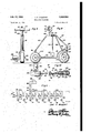
- Figure 1 is a fragmentary rear elevational view of the present invention in use
- Figure 2 is an enlarged vertical sectional View taken substantially on the plane of section line 2-2 of Figure 1;
- Figure 3 is an enlarged end viewof Figure l to illustrate one of the wheeled supports
- Figure 4 is a front view of Figure 3;
- Figure 5 is an enlarged fragmentary plan view of; one of the supply pipes and showing a switch operator,. in dotted lines, in position to the switch on the sunmrpine;
- Figure 6 is a diagrammatic view showing the manner in which a support switch is actuated. by a movement of one pipe relative to an adjacent D 1
- Figure 7 is a rear elevational view of Figure 5 and with part of the support broken away;
- Figure 8 is a front elevational view of one of the supports in modified form
- Figure 9 is a side view of Figure 8;
- Figure 10 is a plan view of Figure 9;
- Figure 11 is a diagrammatic view of the circuit used with the supports. shown in Figures 1-10, inclusive;
- Figure. 12 is an enlarged fragmentary view of Figured.
- the numeral l0 represents a wheeled frame or carriage having a rear pair of wheels i2 and a forward pair of wheels M.
- An electrically operated gear motor I6 is, mounted on the frame and is operatively connected to the forward wheels I4 for driving the wheels [4 and thereby causing the frame to move over the round.
- a well-known pump I 8 is supported on the frame It and includes, a depending inlet '20, preferably in the form. of a flexible tube, whose lower end supports a porouslcone 22.
- the pump l8 also includes a substantially horizontal outlet 24.
- a well-known type of engine 26 is also mounted on theframe it. and is operatively connected to the pump l8 and to a generator 28 mounted on the frame It. The generator, 28 is also operatively connected to the gear motor 16 in any suitable manner.
- a switch 35! is mounted beneath the frame 10 and includes a switch member or swinging switch arm, 32.
- the switch 38 is electrically connected to the gear motor [6 or generator 2d so that the gear motormay be selectively actuated or deeactuated.
- the switch arm 32 is adapted to be. engaged by a post P inserted in the ground to cause the arm 32 to be moved to-its circuit open position and thereby arrest movement of the framev after the frame has moved a. predetermined distance or to a changein slope of the ground.
- a plurality of supply pipes or perforated tubes 34 are associated with each side of the frame ID.
- the innermost tubes 34a. of the tubes 34 are not perforated and are coupled to the two outlet sides of the outlet 18; and the adjacent ends of adjacent tubes. are coupled together by complementary flexible ball and socket or such other universal coupling joints 36 so that the tubes may slope relative to each other. All but the innermost of the tubes 34 support a plurality of depending spray nozzles 38 that constitute the delivery means for liquid passing through the tubes from the pump.
- the tubes 34 are reinforced and strengthened by groups of rods or bars 40 that are terminally pivoted to the ends of the tubes 34.
- Spacer arms 42 are attached to and project radially from the tubes 34 and these arms are secured to the rods 40.
- Each of the tubes 34, 34a is supported by at least one wheeled support 44.
- These supports 44 comprise forward and rear upwardly converging and joined bars or rods 46 and 48 that are connected by connecting bars 50.
- the upper ends of the bars 46 are bent to form forwardly extending hook portions or loops 52 that pivotally support hangers 54 having resilient bands 53 which embrace the tubes 34, 34a.
- the bars 46 and 48 are provided with lower offset ends 58 and 60 that support the axles of forward and rear wheels 62 and 64.
- the wheels 62 and 64, also the wheels I2 and I4 of the frame, are provided with peripheral flanges 66 that will penetrate the ground to prevent shifting of the supports from their intended direction of travel.
- Resilient plates or fingers 68 are fixed to the offset ends 58 and 60, and include slots '10 that receive the flanges 66.
- the plates 68 will scrape dirt collecting on the wheels 62, 64 and thereby will tend to retain the wheel 62, 64 free of dirt.
- Platforms 12 are secured to the ends 58 and support electric gear motors I4 whose drive shafts are connected to the axles of the wheels 62 for driving the latter.
- Electric wires 16 extend from the motors 14, are clamped to the supports 44 and to the tubes 34, 34a, and are connected to the generator 28.
- Each motor 34 is provided with a switch I8 having a spring urged witch member or plunger 80.
- the switches 18 are mounted on the tubes 34, 36 and are disposed at the outer ends of the tubes 34, 34a.
- each tube 34 supports a rigid arm or switch operator 82 that extend across the couplings 36 to engage the plungers 80 of switches 18.
- a master switch 84 is connected to the wires 16 for controlling all of the motors I3, and a. plurality of switches 84a are electrically connected to each of the switches I8 and control the current to the individual motors I4.
- the engine 26 is started to permit the frame I to travel over the ground and, more particularly, over a ditch D in which the inlet 20 is placed.
- a the frame I0 moves forwardly, the pump I8 will direct water through the tubes 34a, 34 and the water will be disposed on the ground through the nozzles 38.
- a flexible supply hose may be attached to the pump if a ditch is not available.
- the arm 82 of the lagging tube will engage the switch member 80 of the leading tube to open the circuit to the leading tubes motor 14 until the lagging tube is advanced by its motored support into alignment with the leading tube.
- the motors 14 will remain in operation as long as the tubes are aligned but should one support be moved ahead of another support then the circuit to the motor of the supp ing ahead will be opened until the lagging support moves up. to the other support.
- the wheeled supports in modified form.
- the wheeled supports are designated by the numeral 90 and consist of forward and rear upwardly converging bars 92 and 94 whose upper ends are joined by a cross bar 96.
- the lower end of the bar 92 is offset to form a portion 98 that supports a forward wheel I00.
- the lower end I02 of the bar 94 supports a vertical bearing I03 in which the vertical portion of an ofiset wheel supporting member I05 is rotatably mounted.
- the member I05 supports a forward wheel I04 and the bearing I03 is connected to the ofiset end 98 by a connector bar I06.
- a sleeve I08 rises from the bar 96 and supports a hook member IIO to which a hanger member II2 is pivotally mounted.
- the hanger member H2 includes a ring or collar II4 that embraces the tube 34.
- a sleeve I I6 is rotatably mounted on the crossbar 96 and support a depending arm II8 to which there is secured a block or weight I 20.
- the forward upwardly curved portion I2I of the connector bar I06 supports a pair of guide rollers I22 over which a pair of cords I 24 and I26 are trained.
- the cords I24 and I26 are attached to the sleeve H6 and to arms I28 and I30 projecting radially from diametrically opposite sides of a collar I3I that is held on the member I05 below the bearing I 03.
- the support automatically maintains a near plumb position, since, when it i out of plumb, the elements II8, I20 move to their vertical position to tension one of the cords and thereby turn or rotate the member I05 in order to maintain the support 90 in its plumb or vertical posi tion. Due to the means actin on the support to retain it in its vertical position, pneumatic wheels I00, I04 may be employed.
- the offset end 98 of the bar 92 supports a platform I32 on which an electric motor I34 is mounted.
- the drive shaft of the motor I 34 is operatively connected to the wheel I00 to drive the latter and the motors I34 of the groups of supports 90 are connected to the generator on the wheeled frame as previously described in Figures 1-7, inclusive, through the medium of a switch for each motor I34 that will be actuated by arms 82 on the tubes 34.
- An irrigation machine comprising a wheeled frame, a pump mounted on the frame and having an outlet and a depending inlet adapted to pas through a water-filled ditch, a plurality of delivery tubes, one of said tubes being attached to the outlet of said pump, flexible couplings joining adjacent; tubes, a wheeled support for each tube, said supports each including a drive wheel, a source of electric current on said frame, an electric motor mounted on each support and connected to said drive wheels for driving the latter, a switch for each motor, and means carried by each tube for actuating the switch associated with an adjacent tube in response to a movement of one tube forwardly relative to an adjacent tube.
- An irrigation machine comprising a wheeled frame, a pump mounted on the frame and havin an outlet and a depending inlet adapted to pass through a. water-filled ditch, a plurality of delivery tubes, one of said tubes being attached to the outlet of said pump, flexible couplings joining adjacent tubes, a wheeled support for each tube, said supports each including a drive wheel, a source of electric current on said frame, an electric motor mounted on each support and operatively connected to the drive wheels for driving the latter, said motors being electrically connected to the source of electric current, a switch for each motor including a sliding switch member, and an arm rigidly secured to each tube, said arms engaging said switch members of adjacent tubes to actuate said switches upon selective movement of one tube forwardly relative to an adjacent tube 3.
- An irrigation machine comprising a wheeled frame, a pump mounted on said frame and including a depending inlet and a horizontal outlet, means mounted on the frame and operatively connected to the pump for operating the latter and also operatively connected to at least one Wheel of the frame for moving the frame over a water-filled ditch in which the inlet is positioned, a plurality of perforated tubes, flexible connectors joining adjacent tubes, at least one of said tubes being connected to said outlet to permit fluid to be delivered to the tubes from the pump, a wheeled support for each tube, said means including an electric motor, and a switch connected to the motor and includin a swingable switch arm'depending from the frame and adapted to engage a post inserted in the ground after the frame has moved a predetermined distance to open a circuit to the motor, and an electric motor on each support, said supports each including a drive wheel, said motors on said supports being connected to a source of current and also operatively connected to the drive wheels, a switch for each motor on the supports, and a switch operator carried
- An irrigation machine comprising a wheeled frame, a pump mounted on the frame and having an outlet and a depending inlet adapted to pass through a Water-filled ditch, a plurality of delivery tubes, one of said tubes being attached to the outlet of said pump, flexible couplings joining adjacent tubes, a wheeled support for each tube, said supports each including a drive wheel, a power means on each support, said power means being operatively connected to said drive wheels, said supports each including a steering wheel, and means mounted on said supports and connected to said steering wheels for retaining the supports plumb.
- said last-named means includes a pendulum on each support, and a pair of flexible connectors between the pendulums and the steering wheels.
Landscapes
- Engineering & Computer Science (AREA)
- Water Supply & Treatment (AREA)
- Life Sciences & Earth Sciences (AREA)
- Environmental Sciences (AREA)
- Catching Or Destruction (AREA)
Description
Feb. 17, 1953 J. FJMAGGART 2,628,863
IRRIGATION MACHINE Filed Oct. 2, 1950 3 Shets-Sheet l I I l I l I I l I l I I I I l I I I I I I I I I I I I I I l N I 'i" \1 I I x I I, l
I I l I Inventor Joel I-'- Magyar! Feb. 17, 1953 Y J. F. MAGGART IRRIGATION MACHINE 3 Sheets-Sheet-Z Filed Oct. 2. 1950 v 2 6 2 w o 6 80 M 6 A5 2 n 4 67 5 1 0 5 4 5 /l[|| 5 f m Fig, 4
Inventor Joel F. Maggarf fiwaaiizuk WW m Patented Feb. 17, 1953 UNITED STATES TENT OFFICE 7 Claims.-.
This invention relates to new and useful improvements in irrigation machines and the primary object of the present invention is to provide an apparatus that will travel over the soil to apply water to the soil, regardless of whether or not the ground is completely level and avoiding the costly portable pipe systems frequently employed.
Another-very important object of the present invention isto provide an irrigation machine includin ,a plurality of flexibly joined delivery pipes mounted on power-driven wheels and a novel and improved means for retaining the pipes lined up to prevent one pipe from moving ahead or lagging behind an adjacent pipe.
Yet another object of the present invention is to provide an irrigation machine including a wheeled frame having a power unit thereon for moving the frame and a pump on the frame and having'a depending inlet that will travel through a supply trough or ditch to direct water in the ditch through supply pipes mounted on wheeled supports adjacent the frame.
A' further object of the present invention is to provide an irrigation machine of the aforementioned character including a switch for the power: means having a depending switch arm thatv will engage a post or stop placed in the ground after the machine has moved a predetermined distance or'to a different grade, to effect a-stopping of the, machine.
A. still" further aim of the present invention isto provide an irrigation machine that is extremely simple and practical in construction, strong and reliable in use, efficient and durable in operation, inexpensive to manufacture, service and operate, and which embodies a novel and improved wheeled support for each delivery tube.
Other objects and advantages reside in the details of construction and operation as more fully hereinafter described and claimed, reference being had to the accompanying drawings forming. part hereof, wherein like numerals refer to'jlike parts throughout, and in which:
Figure 1 isa fragmentary rear elevational view of the present invention in use;
Figure 2 is an enlarged vertical sectional View taken substantially on the plane of section line 2-2 of Figure 1;
Figure 3 is an enlarged end viewof Figure l to illustrate one of the wheeled supports;
Figure 4 is a front view of Figure 3;
Figure 5 is an enlarged fragmentary plan view of; one of the supply pipes and showing a switch operator,. in dotted lines, in position to the switch on the sunmrpine;
Figure 6 is a diagrammatic view showing the manner in which a support switch is actuated. by a movement of one pipe relative to an adjacent D 1 Figure 7 is a rear elevational view of Figure 5 and with part of the support broken away;
Figure 8 is a front elevational view of one of the supports in modified form;
Figure 9 is a side view of Figure 8;;
Figure 10 is a plan view of Figure 9;
Figure 11 is a diagrammatic view of the circuit used with the supports. shown in Figures 1-10, inclusive; and
Figure. 12 is an enlarged fragmentary view of Figured.
Referring now to the drawingsin detail, wherein, for the purpose of illustration, thereissdisclosed a preferred embodiment ofthe present invention, and more particularly referring to Figures 1-7, inclusive, the numeral l0 represents a wheeled frame or carriage having a rear pair of wheels i2 and a forward pair of wheels M. An electrically operated gear motor I6 is, mounted on the frame and is operatively connected to the forward wheels I4 for driving the wheels [4 and thereby causing the frame to move over the round.
A well-known pump I 8 is supported on the frame It and includes, a depending inlet '20, preferably in the form. of a flexible tube, whose lower end supports a porouslcone 22. The pump l8 also includes a substantially horizontal outlet 24. A well-known type of engine 26 is also mounted on theframe it. and is operatively connected to the pump l8 and to a generator 28 mounted on the frame It. The generator, 28 is also operatively connected to the gear motor 16 in any suitable manner.
A switch 35! is mounted beneath the frame 10 and includes a switch member or swinging switch arm, 32. The switch 38 is electrically connected to the gear motor [6 or generator 2d so that the gear motormay be selectively actuated or deeactuated. The switch arm 32 is adapted to be. engaged by a post P inserted in the ground to cause the arm 32 to be moved to-its circuit open position and thereby arrest movement of the framev after the frame has moved a. predetermined distance or to a changein slope of the ground.
A plurality of supply pipes or perforated tubes 34 are associated with each side of the frame ID. The innermost tubes 34a. of the tubes 34 are not perforated and are coupled to the two outlet sides of the outlet 18; and the adjacent ends of adjacent tubes. are coupled together by complementary flexible ball and socket or such other universal coupling joints 36 so that the tubes may slope relative to each other. All but the innermost of the tubes 34 support a plurality of depending spray nozzles 38 that constitute the delivery means for liquid passing through the tubes from the pump.
The tubes 34 are reinforced and strengthened by groups of rods or bars 40 that are terminally pivoted to the ends of the tubes 34. Spacer arms 42 are attached to and project radially from the tubes 34 and these arms are secured to the rods 40.
Each of the tubes 34, 34a is supported by at least one wheeled support 44. These supports 44 comprise forward and rear upwardly converging and joined bars or rods 46 and 48 that are connected by connecting bars 50. The upper ends of the bars 46 are bent to form forwardly extending hook portions or loops 52 that pivotally support hangers 54 having resilient bands 53 which embrace the tubes 34, 34a.
The bars 46 and 48 are provided with lower offset ends 58 and 60 that support the axles of forward and rear wheels 62 and 64. The wheels 62 and 64, also the wheels I2 and I4 of the frame, are provided with peripheral flanges 66 that will penetrate the ground to prevent shifting of the supports from their intended direction of travel.
Resilient plates or fingers 68 are fixed to the offset ends 58 and 60, and include slots '10 that receive the flanges 66. The plates 68 will scrape dirt collecting on the wheels 62, 64 and thereby will tend to retain the wheel 62, 64 free of dirt.
Platforms 12 are secured to the ends 58 and support electric gear motors I4 whose drive shafts are connected to the axles of the wheels 62 for driving the latter. Electric wires 16 extend from the motors 14, are clamped to the supports 44 and to the tubes 34, 34a, and are connected to the generator 28. Each motor 34 is provided with a switch I8 having a spring urged witch member or plunger 80. The switches 18 are mounted on the tubes 34, 36 and are disposed at the outer ends of the tubes 34, 34a.
- The inner end of each tube 34 supports a rigid arm or switch operator 82 that extend across the couplings 36 to engage the plungers 80 of switches 18. A master switch 84 is connected to the wires 16 for controlling all of the motors I3, and a. plurality of switches 84a are electrically connected to each of the switches I8 and control the current to the individual motors I4.
- In practical use of the present invention, as described for Figures 1-7, inclusive, the engine 26 is started to permit the frame I to travel over the ground and, more particularly, over a ditch D in which the inlet 20 is placed. A the frame I0 moves forwardly, the pump I8 will direct water through the tubes 34a, 34 and the water will be disposed on the ground through the nozzles 38. Obviously, a flexible supply hose may be attached to the pump if a ditch is not available.
Should one of the tubes 34 move in advance of an adjacent tube, the arm 82 of the lagging tube will engage the switch member 80 of the leading tube to open the circuit to the leading tubes motor 14 until the lagging tube is advanced by its motored support into alignment with the leading tube. The motors 14 will remain in operation as long as the tubes are aligned but should one support be moved ahead of another support then the circuit to the motor of the supp ing ahead will be opened until the lagging support moves up. to the other support.
Reference is now directed to Figures 8-11, inclusive, wherein there is disclosed the wheeled supports in modified form. In this embodiment, the wheeled supports are designated by the numeral 90 and consist of forward and rear upwardly converging bars 92 and 94 whose upper ends are joined by a cross bar 96.
The lower end of the bar 92 is offset to form a portion 98 that supports a forward wheel I00. The lower end I02 of the bar 94 supports a vertical bearing I03 in which the vertical portion of an ofiset wheel supporting member I05 is rotatably mounted. The member I05 supports a forward wheel I04 and the bearing I03 is connected to the ofiset end 98 by a connector bar I06.
A sleeve I08 rises from the bar 96 and supports a hook member IIO to which a hanger member II2 is pivotally mounted. The hanger member H2 includes a ring or collar II4 that embraces the tube 34.
A sleeve I I6 is rotatably mounted on the crossbar 96 and support a depending arm II8 to which there is secured a block or weight I 20. The forward upwardly curved portion I2I of the connector bar I06 supports a pair of guide rollers I22 over which a pair of cords I 24 and I26 are trained. The cords I24 and I26 are attached to the sleeve H6 and to arms I28 and I30 projecting radially from diametrically opposite sides of a collar I3I that is held on the member I05 below the bearing I 03.
The support automatically maintains a near plumb position, since, when it i out of plumb, the elements II8, I20 move to their vertical position to tension one of the cords and thereby turn or rotate the member I05 in order to maintain the support 90 in its plumb or vertical posi tion. Due to the means actin on the support to retain it in its vertical position, pneumatic wheels I00, I04 may be employed.
The offset end 98 of the bar 92 supports a platform I32 on which an electric motor I34 is mounted. The drive shaft of the motor I 34 is operatively connected to the wheel I00 to drive the latter and the motors I34 of the groups of supports 90 are connected to the generator on the wheeled frame as previously described in Figures 1-7, inclusive, through the medium of a switch for each motor I34 that will be actuated by arms 82 on the tubes 34.
Having described the invention, what is claimed as new is:
1. An irrigation machine comprising a wheeled frame, a pump mounted on the frame and having an outlet and a depending inlet adapted to pas through a water-filled ditch, a plurality of delivery tubes, one of said tubes being attached to the outlet of said pump, flexible couplings joining adjacent; tubes, a wheeled support for each tube, said supports each including a drive wheel, a source of electric current on said frame, an electric motor mounted on each support and connected to said drive wheels for driving the latter, a switch for each motor, and means carried by each tube for actuating the switch associated with an adjacent tube in response to a movement of one tube forwardly relative to an adjacent tube.
2. An irrigation machine comprising a wheeled frame, a pump mounted on the frame and havin an outlet and a depending inlet adapted to pass through a. water-filled ditch, a plurality of delivery tubes, one of said tubes being attached to the outlet of said pump, flexible couplings joining adjacent tubes, a wheeled support for each tube, said supports each including a drive wheel, a source of electric current on said frame, an electric motor mounted on each support and operatively connected to the drive wheels for driving the latter, said motors being electrically connected to the source of electric current, a switch for each motor including a sliding switch member, and an arm rigidly secured to each tube, said arms engaging said switch members of adjacent tubes to actuate said switches upon selective movement of one tube forwardly relative to an adjacent tube 3. An irrigation machine comprising a wheeled frame, a pump mounted on said frame and including a depending inlet and a horizontal outlet, means mounted on the frame and operatively connected to the pump for operating the latter and also operatively connected to at least one Wheel of the frame for moving the frame over a water-filled ditch in which the inlet is positioned, a plurality of perforated tubes, flexible connectors joining adjacent tubes, at least one of said tubes being connected to said outlet to permit fluid to be delivered to the tubes from the pump, a wheeled support for each tube, said means including an electric motor, and a switch connected to the motor and includin a swingable switch arm'depending from the frame and adapted to engage a post inserted in the ground after the frame has moved a predetermined distance to open a circuit to the motor, and an electric motor on each support, said supports each including a drive wheel, said motors on said supports being connected to a source of current and also operatively connected to the drive wheels, a switch for each motor on the supports, and a switch operator carried by eachtube for engaging and actuating a switch of an adjacent tube upon movement of one tube forwardly relative to an adjacent tube.
4. The combination of claim 3 wherein said drive wheels include peripheral flanges for penetrating the ground.
' 5. The combination of claim 4 and a resilient plate carried by each support, said plates overlying the drive wheels and having slots receiving said flanges.
6. An irrigation machine comprising a wheeled frame, a pump mounted on the frame and having an outlet and a depending inlet adapted to pass through a Water-filled ditch, a plurality of delivery tubes, one of said tubes being attached to the outlet of said pump, flexible couplings joining adjacent tubes, a wheeled support for each tube, said supports each including a drive wheel, a power means on each support, said power means being operatively connected to said drive wheels, said supports each including a steering wheel, and means mounted on said supports and connected to said steering wheels for retaining the supports plumb.
7. The combination of claim 6 wherein said last-named means includes a pendulum on each support, and a pair of flexible connectors between the pendulums and the steering wheels.
JOEL F. MAGGART.
REFERENCES CITED The following references are of record in the file of this patent:
UNITED STATES PATENTS Number Name Date 1,085,609 Heath Feb. 3, 1914 1,321,350 Alvarez Nov. 11, 1919 1,468,860 Foley Sept. 25, 1923 1,966,783 Balaam July 17, 1934 2,563,519 Egly Aug. '7, 1951 FOREIGN PATENTS Number Country Date 414,551 Germany June 9, 1925
Priority Applications (1)
| Application Number | Priority Date | Filing Date | Title |
|---|---|---|---|
| US187867A US2628863A (en) | 1950-10-02 | 1950-10-02 | Irrigation machine |
Applications Claiming Priority (1)
| Application Number | Priority Date | Filing Date | Title |
|---|---|---|---|
| US187867A US2628863A (en) | 1950-10-02 | 1950-10-02 | Irrigation machine |
Publications (1)
| Publication Number | Publication Date |
|---|---|
| US2628863A true US2628863A (en) | 1953-02-17 |
Family
ID=22690823
Family Applications (1)
| Application Number | Title | Priority Date | Filing Date |
|---|---|---|---|
| US187867A Expired - Lifetime US2628863A (en) | 1950-10-02 | 1950-10-02 | Irrigation machine |
Country Status (1)
| Country | Link |
|---|---|
| US (1) | US2628863A (en) |
Cited By (29)
| Publication number | Priority date | Publication date | Assignee | Title |
|---|---|---|---|---|
| US2718433A (en) * | 1952-05-13 | 1955-09-20 | Int Harvester Co | Self-propelled irrigation apparatus |
| US2731295A (en) * | 1954-06-21 | 1956-01-17 | Raymond M Snow | Spraying apparatus |
| US2744785A (en) * | 1953-07-13 | 1956-05-08 | Alma J Lundegreen | Mobile sprinkler |
| US2756098A (en) * | 1952-10-04 | 1956-07-24 | Rottcher Kurt Karl | Self-propelled, automatic, overhead irrigation plant |
| US2800364A (en) * | 1955-03-08 | 1957-07-23 | Gustav Thieszen | Irrigating apparatus, including pipe alignment means |
| US2807500A (en) * | 1955-06-01 | 1957-09-24 | Clayton William | Self propelled irrigation apparatus |
| US2843424A (en) * | 1953-10-30 | 1958-07-15 | Harry William Weston | Spraying booms |
| DE1039776B (en) * | 1953-10-30 | 1958-09-25 | Harry William Weston | Sprinkler or sprinkler frame to be attached to a vehicle |
| US2893643A (en) * | 1956-06-18 | 1959-07-07 | Allen J Gordon | Ambulant discharge irrigating device |
| US2941727A (en) * | 1953-06-15 | 1960-06-21 | Frank L Zybach | Self-propelled sprinkling irrigating apparatus |
| DE1192445B (en) * | 1960-09-10 | 1965-05-06 | Vyzk Ustav Zemedelskych Stroju | Device for the mechanical control of the driving speed of self-propelled chassis of irrigation systems |
| US3202361A (en) * | 1963-09-12 | 1965-08-24 | Kane David | Mobile irrigation device |
| US3268174A (en) * | 1963-09-27 | 1966-08-23 | Ralph D Boone | Irrigation system |
| US3385315A (en) * | 1965-02-16 | 1968-05-28 | Decoto Brothers Irrigation Div | Irrigation system |
| US3406907A (en) * | 1966-09-19 | 1968-10-22 | David A. Wallace | Irrigating device |
| US3519206A (en) * | 1968-11-20 | 1970-07-07 | Otto W Leaders | Traveling water supply for field irrigation system |
| US3701358A (en) * | 1970-06-22 | 1972-10-31 | Carl V Von Linsowe | Articulated frame for mobile ground-traveling instrumentality |
| US3707164A (en) * | 1970-06-24 | 1972-12-26 | Victor G Clemons | Line move |
| US3726478A (en) * | 1971-03-29 | 1973-04-10 | Irrigation Power Equip Inc | Moving pivot sprinkler irrigation system |
| US3771719A (en) * | 1971-04-09 | 1973-11-13 | Emerson Electric Co | Wheel modules for overhead tracking sprinkler system |
| US3784106A (en) * | 1971-02-25 | 1974-01-08 | W Ross | Irrigation center pivot structure |
| US3951341A (en) * | 1975-05-07 | 1976-04-20 | Jenkins Elton E | Irrigation vehicle |
| US4161185A (en) * | 1978-05-12 | 1979-07-17 | Tumac Industries, Inc. | Alignment control apparatus for a self-propelled irrigation system |
| US4182493A (en) * | 1978-02-21 | 1980-01-08 | Murray Larry C | Self-propelled irrigation apparatus |
| US4378089A (en) * | 1980-03-04 | 1983-03-29 | Tate & Lyle Limited | Surface irrigation apparatus |
| US4463906A (en) * | 1982-09-22 | 1984-08-07 | Reinke Manufacturing Co., Inc. | Guidance system for lateral move irrigation machines |
| US5078326A (en) * | 1991-01-24 | 1992-01-07 | Wright Hubbard L | Mobile irrigation equipment belt traction apparatus |
| DE19814032A1 (en) * | 1998-03-30 | 1999-10-14 | Herbert Schneider Gmbh | Floor dampening system for horse-riding hall |
| ITVR20130240A1 (en) * | 2013-11-06 | 2015-05-07 | Meccanica Cremonini Di Fabio E Dari O Cremonini S | COMBINED DEVICE FOR MULTIFUNCTIONAL SERVICES, IN PARTICULAR FOR IRRIGATION IN AGRICULTURAL COMPANY, FOR FOREST SERVICES AND FOR TERRITORY PROTECTION |
Citations (6)
| Publication number | Priority date | Publication date | Assignee | Title |
|---|---|---|---|---|
| US1085609A (en) * | 1912-12-11 | 1914-02-03 | Harry Clark Heath | Automatic irrigator. |
| US1321350A (en) * | 1919-11-11 | oe tunis | ||
| US1468860A (en) * | 1920-08-16 | 1923-09-25 | Timothy J Foley | Sprinkling apparatus |
| DE414551C (en) * | 1921-11-16 | 1925-06-09 | Ernst Zander | Mobile rain device |
| US1966783A (en) * | 1932-03-17 | 1934-07-17 | Rain Machine Ltd | Portable overhead irrigation plant |
| US2563519A (en) * | 1951-08-07 | Traveling lawn sprinkler |
-
1950
- 1950-10-02 US US187867A patent/US2628863A/en not_active Expired - Lifetime
Patent Citations (6)
| Publication number | Priority date | Publication date | Assignee | Title |
|---|---|---|---|---|
| US1321350A (en) * | 1919-11-11 | oe tunis | ||
| US2563519A (en) * | 1951-08-07 | Traveling lawn sprinkler | ||
| US1085609A (en) * | 1912-12-11 | 1914-02-03 | Harry Clark Heath | Automatic irrigator. |
| US1468860A (en) * | 1920-08-16 | 1923-09-25 | Timothy J Foley | Sprinkling apparatus |
| DE414551C (en) * | 1921-11-16 | 1925-06-09 | Ernst Zander | Mobile rain device |
| US1966783A (en) * | 1932-03-17 | 1934-07-17 | Rain Machine Ltd | Portable overhead irrigation plant |
Cited By (29)
| Publication number | Priority date | Publication date | Assignee | Title |
|---|---|---|---|---|
| US2718433A (en) * | 1952-05-13 | 1955-09-20 | Int Harvester Co | Self-propelled irrigation apparatus |
| US2756098A (en) * | 1952-10-04 | 1956-07-24 | Rottcher Kurt Karl | Self-propelled, automatic, overhead irrigation plant |
| US2941727A (en) * | 1953-06-15 | 1960-06-21 | Frank L Zybach | Self-propelled sprinkling irrigating apparatus |
| US2744785A (en) * | 1953-07-13 | 1956-05-08 | Alma J Lundegreen | Mobile sprinkler |
| US2843424A (en) * | 1953-10-30 | 1958-07-15 | Harry William Weston | Spraying booms |
| DE1039776B (en) * | 1953-10-30 | 1958-09-25 | Harry William Weston | Sprinkler or sprinkler frame to be attached to a vehicle |
| US2731295A (en) * | 1954-06-21 | 1956-01-17 | Raymond M Snow | Spraying apparatus |
| US2800364A (en) * | 1955-03-08 | 1957-07-23 | Gustav Thieszen | Irrigating apparatus, including pipe alignment means |
| US2807500A (en) * | 1955-06-01 | 1957-09-24 | Clayton William | Self propelled irrigation apparatus |
| US2893643A (en) * | 1956-06-18 | 1959-07-07 | Allen J Gordon | Ambulant discharge irrigating device |
| DE1192445B (en) * | 1960-09-10 | 1965-05-06 | Vyzk Ustav Zemedelskych Stroju | Device for the mechanical control of the driving speed of self-propelled chassis of irrigation systems |
| US3202361A (en) * | 1963-09-12 | 1965-08-24 | Kane David | Mobile irrigation device |
| US3268174A (en) * | 1963-09-27 | 1966-08-23 | Ralph D Boone | Irrigation system |
| US3385315A (en) * | 1965-02-16 | 1968-05-28 | Decoto Brothers Irrigation Div | Irrigation system |
| US3406907A (en) * | 1966-09-19 | 1968-10-22 | David A. Wallace | Irrigating device |
| US3519206A (en) * | 1968-11-20 | 1970-07-07 | Otto W Leaders | Traveling water supply for field irrigation system |
| US3701358A (en) * | 1970-06-22 | 1972-10-31 | Carl V Von Linsowe | Articulated frame for mobile ground-traveling instrumentality |
| US3707164A (en) * | 1970-06-24 | 1972-12-26 | Victor G Clemons | Line move |
| US3784106A (en) * | 1971-02-25 | 1974-01-08 | W Ross | Irrigation center pivot structure |
| US3726478A (en) * | 1971-03-29 | 1973-04-10 | Irrigation Power Equip Inc | Moving pivot sprinkler irrigation system |
| US3771719A (en) * | 1971-04-09 | 1973-11-13 | Emerson Electric Co | Wheel modules for overhead tracking sprinkler system |
| US3951341A (en) * | 1975-05-07 | 1976-04-20 | Jenkins Elton E | Irrigation vehicle |
| US4182493A (en) * | 1978-02-21 | 1980-01-08 | Murray Larry C | Self-propelled irrigation apparatus |
| US4161185A (en) * | 1978-05-12 | 1979-07-17 | Tumac Industries, Inc. | Alignment control apparatus for a self-propelled irrigation system |
| US4378089A (en) * | 1980-03-04 | 1983-03-29 | Tate & Lyle Limited | Surface irrigation apparatus |
| US4463906A (en) * | 1982-09-22 | 1984-08-07 | Reinke Manufacturing Co., Inc. | Guidance system for lateral move irrigation machines |
| US5078326A (en) * | 1991-01-24 | 1992-01-07 | Wright Hubbard L | Mobile irrigation equipment belt traction apparatus |
| DE19814032A1 (en) * | 1998-03-30 | 1999-10-14 | Herbert Schneider Gmbh | Floor dampening system for horse-riding hall |
| ITVR20130240A1 (en) * | 2013-11-06 | 2015-05-07 | Meccanica Cremonini Di Fabio E Dari O Cremonini S | COMBINED DEVICE FOR MULTIFUNCTIONAL SERVICES, IN PARTICULAR FOR IRRIGATION IN AGRICULTURAL COMPANY, FOR FOREST SERVICES AND FOR TERRITORY PROTECTION |
Similar Documents
| Publication | Publication Date | Title |
|---|---|---|
| US2628863A (en) | Irrigation machine | |
| US3352493A (en) | Self propelled irrigator | |
| US2941727A (en) | Self-propelled sprinkling irrigating apparatus | |
| US2931579A (en) | Automatic irrigation system | |
| US2221433A (en) | Spray machine | |
| US2076172A (en) | Apparatus for spraying a center stripe on highways | |
| US1429756A (en) | Irrigating machine | |
| US2796292A (en) | Mobile pipeline spray apparatus | |
| US2718433A (en) | Self-propelled irrigation apparatus | |
| US3034668A (en) | Pipe handling machine | |
| US2196880A (en) | Ballast cleaning machine | |
| CN108940981A (en) | A kind of high-pressure water jet removes concrete mechanism | |
| US2544113A (en) | Turntable road machine | |
| US2974876A (en) | Portable irrigation apparatus | |
| US2940672A (en) | Traveling sprinkler system | |
| US2830510A (en) | Machine for distributing road building materials | |
| US2892593A (en) | Ambulant land working and irrigating apparatus | |
| US3465766A (en) | Ambulatory irrigating device | |
| US2248709A (en) | Elevating grader | |
| US3689318A (en) | Apparatus and method for washing trailer interiors | |
| US1896901A (en) | Tractor power coupling mechanism | |
| US2078310A (en) | Snow removing attachment for trucks | |
| US3616477A (en) | Power driven road sweeper with laterally and angularly adjustable brush | |
| US2092536A (en) | Snow removing apparatus | |
| SU434918A1 (en) | THE DEVICE FOR THE COLLECTION AND SUPPLY OF WATER TO THE RAINWAY CAR IN MOTION |