US2628583A - Rotary take-up lock stitch machine - Google Patents
Rotary take-up lock stitch machine Download PDFInfo
- Publication number
- US2628583A US2628583A US100619A US10061949A US2628583A US 2628583 A US2628583 A US 2628583A US 100619 A US100619 A US 100619A US 10061949 A US10061949 A US 10061949A US 2628583 A US2628583 A US 2628583A
- Authority
- US
- United States
- Prior art keywords
- thread
- shaft
- path
- take
- cover
- Prior art date
- Legal status (The legal status is an assumption and is not a legal conclusion. Google has not performed a legal analysis and makes no representation as to the accuracy of the status listed.)
- Expired - Lifetime
Links
- 238000009958 sewing Methods 0.000 description 19
- 239000000314 lubricant Substances 0.000 description 14
- 230000009471 action Effects 0.000 description 7
- 238000005461 lubrication Methods 0.000 description 5
- 238000010276 construction Methods 0.000 description 4
- 210000000887 face Anatomy 0.000 description 4
- 239000003595 mist Substances 0.000 description 4
- 230000002159 abnormal effect Effects 0.000 description 2
- 230000000694 effects Effects 0.000 description 2
- 230000001154 acute effect Effects 0.000 description 1
- 229910052729 chemical element Inorganic materials 0.000 description 1
- 230000007423 decrease Effects 0.000 description 1
- 230000007246 mechanism Effects 0.000 description 1
- 230000004048 modification Effects 0.000 description 1
- 238000012986 modification Methods 0.000 description 1
- 239000002991 molded plastic Substances 0.000 description 1
- 230000003534 oscillatory effect Effects 0.000 description 1
- 238000005192 partition Methods 0.000 description 1
- 230000002093 peripheral effect Effects 0.000 description 1
- 230000000717 retained effect Effects 0.000 description 1
- 101150065339 secF gene Proteins 0.000 description 1
- 239000007921 spray Substances 0.000 description 1
Images


Classifications
-
- D—TEXTILES; PAPER
- D05—SEWING; EMBROIDERING; TUFTING
- D05B—SEWING
- D05B51/00—Applications of needle-thread guards; Thread-break detectors
Definitions
- This invention relates to lockstitch sewing machines and more particularly to rotary take-up devices on'such machines for controlling and taking up the needle thread.
- Lockstitoh machines require the yielding and taking up of a substantial amount of needle thread on each cycle of the machine.
- Oscillatory take-up devices khave been found objectionable for various reasons. When operated at high speeds they set up vibrations which interfere with the proper operation vof the machine and in general they have a greater tendency to break the thread than rotary take-ups and are not capable of such accurate control of the thread.
- Rotary take-ups as heretofore constructed have also led to various difficulties due to improper engagement of the thread by the take-up elements at times, and particularly upon breakage of the thread.
- a primary object of the present invention has been to provide a rotary take-up which will at all times, during normal operation, exercise the desired control over the thread and will also reduce to a minimum the abnormal or improper engagement of the thread withA the take-up means. Such abnormal engagement can occur only upon breakage of the thread and is then conlined to a brief interval even though the operation of the machine continues.
- Another object has been to provide for the quick and ready removal of any thread which is severed in the operation of the foregoing devices, thereby preventing subsequent interference with the take-up action when the machine is rethreaded.
- Another object has been to provide for the quick and easy threading of the take-up means in a manner to insure proper engagement'of the thread with the various controlling means;
- Still another object has been to provide means for the effective lubrication of the various bearing surfaces of the take-up and its operating' means, together with the lubrication of the other operative devices of the machine.
- a special feature of the invention is the provision of a relatively thin or 'narrow circular' thread confining passage in the region of an orbitally movable takeeup element 'to prevent whipping of the thread .aS it is being taken up 1949, Serial No. 100,619
- annular guard rim in association with the orbital take-up element for retaining the thread' thereon so long as it is properly threaded.
- This guard rim is arranged to cooperate at all times with an arcuate groove in the outer face of the take-up element. It is also provided with. an inclined shoulder adapted to remove thread from 'the take-up element whenever it has become Wrapped around it vor otherwise improperly engaged with it.
- the guard rim in its preferred form, varies in Width around its circumference so that it enters the slot in the take-up element to a greater extent at certain points in the travel of the element than at others. This provides for more perfect control of the thread and insures its proper engagement with the orbital take-up element at all times in the movement of thelatter through its orbital path.
- a further feature is the provision of a slight inclination or slope to one of the thread engaging edges of the orbital take-up element. This facilitates removal of the thread vfrom the latter when it has become Wrapped about it after breakage. At the same time the inclined edge is so disposed as not to interfere with the normal functioning of the take-up element.
- Fig.. 1 is a vertical sectional view through the main longitudinal axis of a machine embodying the invention
- Fig. 2 is an end elevation of the machine as seen from the left in Fis. 1:
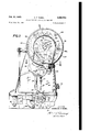
- Fig. 4 is an enlarged detail view showing, in front elevation, the needle head of the machine and various associated parts;
- Fig. 5 is an enlarged detail view in end elevation of the upper portion of the machine, as seen from the left in Fig. 1, with the needle head cover and associated parts removed;
- Fig. 6 is a bottom plan view of the machine with certain parts broken away to illustrate features normally concealed thereby;
- Fig. 7 is an enlarged detail view, in longitudinal section through a modified form of rotary hook and its shaft showing a different means of lubrication of the hook raceway;
- Fig. 8 is a transverse sectional view through the shaft of Fig. 7, taken along the line 8 8;
- Fig. 9 is a vertical sectional view through the take-up devices and the enclosure therefor, taken along the axis thereof;
- Fig. 10 is an edge view, as seen from the front of the machine, of a cover member for the needle head and parts assembled therewith;
- Fig. 11 is a face view of the inner side of the cover assembly
- Fig. 12 is a detail, in plan, showing a modified form of knife element for the cover ⁇ assembly on an enlarged scale;
- Fig. 13 is a detail view showing the mounting of the knife element of Fig. 12;
- Figs. 14 and 15 are, respectively, a face view and an edge view of a disc element forming part of the rotary take-up;
- Fig. 16 and Fig. 1'7 are, respectively, a face view and an edge view of a companion disc element forming part of the rotary take-up;
- Fig. 18 is a face view of a disc-like member, the edge of which is adapted to have a camming action on the thread in effecting a take-up;
- Fig. 19 is a sectional view through the member of Fig. 18 taken along the line Iii-I9;
- Fig. 20 is a face view of a partial closure member for the rotary take-up housing
- Fig. 21 is a detail view in section along the line 2I-2I of Fig. 20;
- Fig. 22 is a detail view in horizontal section through a portion of the take-up housing, taken along the line 22-22 of Fig. 2;
- Fig. 23 is an edge view of a thread retaining, guiding and stripping member carried by the take-up cover
- Fig. 24 is a face view of the part shown in Fig. 23;
- Fig. 25 is an edge view of the same part taken in the direction indicated by the arrows 25-25 in Fig. 24;
- Figs. 26 and 27 are, respectively, a side View and an end view of an orbitally moving take-up element
- Fig. 28 is a face view of the inner side of a modified form of cover member for the rotary take-up;
- Fig. 29 is an edge view of the cover member of Fig. 28 taken in the direction indicated by the arrows 29-29 in Fig. 28;
- Fig. 30 is an outer face view of the modified cover member, shown applied to the needle head;
- Fig. 31 is an edge view of said cover member as viewed from the right of Fig. 30;
- Fig. 32 is a sectional view through the cover member taken along the line 32-32 of Fig. 28.
- the main frame of the machine as best shown in Fig. 1, comprises a base or work supporting portion I0, a vertical standard II, and an overhanging arm I2 terminating at its free end in a needle head I3.
- a main driving shaft I4 Extending longitudinally of the overhanging arm is a main driving shaft I4 which is journalled near its inner end in a needle bearing I5 carried by a partition wall I6 which serves to separate the overhanging arm from the needle head.
- a needle bearing I1 Adjacent its opposite end the shaft I4 is journalled in a needle bearing I1 carried by the end wall of the vertical standard.
- the shaft projects beyond the latter and carries at its outer end a combined handwheel and pulley I8.
- Within the needle head there is secured to the shaft I4 a balanced crank I9 connected by a link or pitman 20 with a block 2
- the latter carries a needle 23 adapted to be reciprocated from a point above the base I0 to a point below the work supporting surface of the latter.
- a spring 24a surrounding the presser bar urges the presser foot toward the work supporting surface.
- Suitable means which need not be described, are provided for lifting the presser bar whenever desired.
- a pulley 26 which is connected by a belt 21 with another pulley 28 secured to a shaft 29 parallel with the shaft I4, but disposed within the base of the machine below the work supporting surface.
- the belt 21 is preferably formed of a molded plastic which is resistant to oil and provided with toothlike projections on its inner surface adapted to cooperate with corresponding recesses in the pulley wheels 28 and 28 to effect a substantially positive driving connection bctween the shafts I4 and 29. If desired. these shafts may be connected by suitable gearing, such as shown in said patent to Christensen, et al. No. 2,113,572 or in the patent to Rubel No. 2,480,602, granted May 2l. 1946.
- Shaft 29 is journalled adjacent its right end in a bearing sleeve 33 and near its left end in suitable bearing rings or sleeves carried by a downwardly extending portion 3
- Portion 3I is constructed to provide a small enclosure adapted to retain a lubricant and serving to house a gear 32 secured to the shaft 23 and cooperating pinion 33 secured to a hollow shaf t 34.
- the latter is journalled within a sleeve 35 carried by the base portion of the frame and is arranged to be driven at twice the angular speed of the shaft 29.
- the shaft 34 At its outer or lefthand end (Fig. 6) the shaft 34 carries the rotary component of a rotary hook 36.
- Any suitable means may be provided for leeding the work in relation to the stitch forming clevices to effect the desired seam.
- These may include an eccentric 31 carried by the shaft 29 and arranged to cooperate with a strap 38 (Fig. 6) seing of any thread wrapped about the surface 80, since the actual periphery of a transverse secF tion through this surface gradually decreases in length toward the outer end of the element.
- annular member 85 (Figs. 1, 9, 11, 23, 24, and 25) adapted to lic fia-t against the inner face of the cover and having extending therefrom a flange or rim 85 which is substantially a full annulus.
- This is the flange, above mentioned, which extends into the arcuate groove 8
- the flange 85 is of varying width. For about 150 of its circumference it is relatively narrow, as indicated at the left end of Fig. 25. It gradually increases in width, however, along an inclined edge 86 to the width indicated at the right end of Fig, 25.
- This width is continued up to a break or slot 81 which is inclined to the axis of the flange and, because of the curvature of the flange, is slightly helical.
- An arcuately formed finger 89 is provided on the flange just above the shoulder 88, this finger being spaced from the narrow portion of the flange 85 by a slot 90.
- the needle thread passes through the slot 90 in its course from the guide 12 to the element 6
- Rounding of the free end of the finger 89 serves to facilitate the passage of the thread into and out of the slot 90 as the element 0
- Suitable thread severing means is provided for cutting off from the main supply any thread which has become wound about the element 8
- (Fig. 11) is formed at the lower end of a blade 92 secured to the inner face of the cover 15 by means of a screw 93.
- This blade is preferably located just outside of the iiange 85 and preferably has a small extension, as shown in Fig. ll, passing through an opening in said fiange.
- the inner face of the cover is provided with a recess 94 in the region of this edge, so that the latter is spaced slightly from the adjacent surface of the cover.
- permits the severed section oi' thread t0 be readily removed from the element 6 I. Such thread will, in fact, be forced partly or completely through said opening by the camming and stripping action of the shoulder 88, the outer end of which is positioned at the opening.
- FIG. 12 A modied arrangement for severing the thread is illustrated in Figs. 12 and 13.
- a cutting edge 96 is provided on a blade 91 having an opening 98 adapted to receive a screw 99 by which it may be secured to the thread guiding element 12.
- the latter has a threaded opening to receive the end of the screw 99.
- the blade 91 extends radially inward from the guide element 12 in a manner to position the cutting edgeA 98 along substantially the same line as the cutting edge 9
- the inner end of the blade has an 8 extension
- Substantially complete enclosure of the takeup device is provided by the rim 69, plate 10, cover 15, and several partial closures now to be described. These include a member
- is provided with a finger
- This finger is preferably bent, in the manner indicated in Fig. 21, first inwardly at
- Cover member 15 is provided with a recess
- the rim or flange 69 of the housing is bent outwardly at its lowermost point to form a finger
- a slight gap is provided between the end of this finger and the surface of the member 16 to permit the introduction of the thread in the course of threading the machine.
- 08 there is no danger of outward movement of the thread from its desired path in the regular operation of the machine.
- 0 is flxedly mounted on the inner face of the cover 15 and a disc is mounted on the outer face of member 60 for rotation therewith.
- 0 has a small hub-like extension I
- the inner face of the disc is rabbeted as indicated at
- the screw I3 may serve to retain both member 84 and disc 0 in assembled relation on the cover.
- 0 is beveled, as indicated at I
- I6 of the disc is preferably flat.
- Disc is provided with a recess
- a radially extending passage i 9 has a reduced inner portion which is threaded to receive a set screw ('Fig'. 9.) for securing the disc to the shaft 56'.
- the outer periphery of the disc is beveledl as shown at
- the angle of this bevel is preferably slightly different from that of the disck H0. It has been found desirable to make it about 35 to the axis of the disc.
- 'I-he outer' faceA of disc is flat, in a plane normal to the axis of: the disc, in a circular area adjacent the center of the disc, but froma circle indicated by the, point i
- the various moving and stationary parts of the thread take-.up and. guiding means are such as to maintain accurate. control over the thread. Little slack is provided at any time a1- though a limited amount of slack is always. present, except as the stitches are being set, to avoid undue tension upon the thread.
- the rim or flange 85,. projecting inwardly from. the cover member plays a part ink the accurate control of the thread through the4 variation in the width of this i'iange.
- ⁇ lit serves tol retain the thread on the take-up element
- Finger t3 and guide slot 30 serve to catch and retain the thread at certain points in the cycle and the shoulder 88 performs the stripping action above described, whenever the thread becomes abnormally or improperly wound about the element 6
- 24!V is formed at the base of. the vertical standard and lubricant is normally retained in thistoy the level indicated iny Fig. 1.
- 25 (Fig. 3) is provided over a portion of the top ofthe standard, this being of suitable contour to accommodate the gear 55.
- a portion of the lubricant mist in the standard will be delivered to this gear and gear 54 as well aste various other surfaces requiring lubrica-v tion.
- Gear 32 and pinion 33 are lubricated by a mist gener,- ate'd by gear 32 from a bodyv of lubricant
- lubrication of the hook raceway may be accomplishedin a manner similar to that dis ⁇ closed in the application of Christensen and ⁇ Rubel, Serial No. 694,688, led September 4, 1946 now Patent No. 2,530,860 dated Nov. 21, 1950.
- 29 is provided beneath the work supporting surface of the base' and this communicates with the end of the hollow hook shaft 34.
- 30 is provided to assist in feeding the lubricant toward the left to the hook raceway.
- Fig'. 7 there is' shown la' modified arrangement for supplying lubricant to ⁇ the hook race way. This is similar to that shown in Fig. 6, ex- ⁇ cept for the replacement ofv the spiral member
- the right hand end of thisl rod is reduced in diameter, as indicated at
- 33 of suitable depth and width and disposed parallel with'thel axis ot the rod, communicates with a narrow slot or groove
- 35 is' such as to permit the passage' of only the right amount of lubricant to supply the requirements of the hook raceway.
- Such'lubricant is delivered into the pocket
- fits snugly within the bore of the shaft and turns as a unit with the latter.
- 40 is preferably elevated slightly from the corresponding surface of portion
- 42 projects laterally from the outer edge of the circular portion
- 42 is a. substantially complete annular rim or flange
- 44 is provided diagonally across the flange
- That part of the flange which carries the shoulder projects a somewhat greater distance from the inner face of the cover than does the adjacent part of the flange at the opposite side of the slot, and it is formed to provide a thread retaining finger
- 40 of the cover a raised disclike formationv
- 49 are provided in the portion
- 40a on the inner face of the cover (similar to recess
- the left edge of the cover, as viewed in Fig. 28, is recessed, as indicated at
- 55 serves to retain the guide member in position.
- 52, is provided for clearance purposes with respect to a screw
- 00 of Fig. 12. is adapted to enter an opening
- the cover On its outer face, the cover is provided with a relatively large recess
- the edge of the cover presents a flat surface provided with screw threaded holes
- a rotary take-up which comprises a rotary shaft, a discllke member secured to said shaft, an orbitally imovable thread engaging element carried by' said member and projecting laterally therefrom, said element having anv arcuate groove in the outer face thereof curved about the axis of said shaft, and a fixed cover member parallel with the path of movement of said element and disposed adjacent said path, said cover member carrying a substantially continuous circular flange extending into the path of said element and ar ranged to be received by said arcuate groove in said element. said flange cooperating with the thread properly engaged by said element to retain the same thereon.
- a rotary take-up which comprises a rotary shaft, a disclike member secured to said shaft, an orbitally movable thread engaging element carried by said member and projecting laterally therefrom, said element having an arcuate groove in the outer face thereof curved about the axis of said shaft, and a fixed cover member parallel with the path of movement of said element and disposed adjacent said path, said cover member carrying a substantially continuous circular flange extending into the path of said element and arranged to be received by said arcuate groove in said element, said flange cooperating with the thread properly engaged by said element to retain the same thereon and said flange having an opening therein providing a diagonally disposed shoulder arranged to engage and remove any thread which may become abnormally wound around said ele ment.
- a rotary take-up which comprises a rotary shaft, a disclike member secured to said shaft, an orbitally movable thread engaging element carried by said member and projecting laterally therefrom, said element having an arcuate groove in the outer face thereof curved about the axis of said shaft, and a fixed cover member parallel with the path of movement of said element and disposed adjacent said path, said cover member carrying a substantially continuous circular flange extending into the path of said element and arranged to be received by said arcuate groove in said element, said flange having a portion extending into said groove a greater distance than another portion thereof, and the free edge of said flange serving to engage the thread and retain the same at different positions along the face of said element.
- a rotary take-up which comprises a rotary shaft, a disclike member secured to said shaft, an orbitally movable thread engaging element carried by said member and projecting laterally therefrom, said element having an arcuate groove in the outer face thereof curved about the axis of said shaft, and a ilxed cover member parallel with the path of movement of said element and disposed adjacent said path, said cover member carrying a substantially continuous circular flange extending into the path of said element and arranged to be received by said arcuate groove in said element, said flange cooperating with the thread properly engaged by said element to retain the same thereon and said flange having an opening therein providing a diagonally disposed shoulder arranged to engage and remove any thread which may become abnormally wound around said element, said diagonally disposed shoulder extending into said arcuate groove a greater distance than the adjacent portion of the flange at the opposite side of said opening.
- a rotary takefup which comprises a rotary shaft, a disclike member secured to said shaft, an orbitally movable thread engaging element carried by said member and projecting laterally therefrom, said element having an arcuate groove in the outer face thereof curved about the axis of said shaft, and a fixed cover member parallel with the path of movement of said element and disposed adjacent said path, said cover member carrying a substantially continuous circular fiange extending into the path of said element and arranged to be received by said arcuate groove in said element, said flange having a slot therein disposed at an angle to an element of the cylindrical surface of the iiange, thereby providing a shoulder for engagement of thread abnormally wound about said element, said shoulder being so arranged that its outer end rst enters said groove in the element as the latter is carried around its orbital path, the portion of said fiange which carries said shoulder extending into said groove further than the adjacent portion at the yopposite side of said slot.
- a rotary take-up which comprises a rotary shaft, a disclike member secured to said shaft, an orbitally movable thread engaging element carriedby said member and projecting laterally therefrom, said element having an-arcuate groove in the outer face thereof vcurved about the axis of said shaft, and a fixed cover member parallel with the path of movement of said element and disposed adjacent said path, said cover member carrying a substantially continuous circular, iiange extend- ⁇ ing into the path of said element and arranged to be received by said arcuate groove in said element, said flange having a slot therein disposed at an angle to an element ofthe cylindrical surface of the flange, thereby providing a shoulder for engagement of thread abnormally wound about said element, said shoulder being so a1'- ranged that its outer end rst enters saidgroove in the element as the latter is carried around its orbital path, the portion of -said flange which carries said shoulder extending into said groove further than the adjacent portion at the
- a rotary take-up which ⁇ comprises a rotary shaft, a ldisclike member secured to said shaft, an orbitally movable thread engaging element carried by said member and projecting laterally therefrom, said element having an arcuate groove in 'theouter face thereof curved about the ax'isgof said shaft.
- a rotary take-up which comprises a rotaryshaft, a disclike member secured to said shaft. an 'orbitally movable thread engaging element carried bysaid member and'projecting laterally therefrom,saidi element having an arcuate groove 4in thercuter' face thereof curved about the axis of said shaft, a fixed cover member parallel with the path of movement .of said element and disposed adjacent said path, said cover member having associated therewith an arcuate thread positioning member arranged to pass through said arcuate groove upon the orbital movement of' said element, and means carried by said disc-like member and by said cover presenting closely-spaced substantially parallel surfaces which provide a narrow thread confining channel in the plane of the path of said element.
- a rot-ary take-up which comprises a rotary shaft, avdisclike member secured to said shaft, an orbitally movable thread engaging element carried by said member and yprojecting laterally therefrom, said element having an arcuate groove in the outer face thereof curved about the axis of said shaft, a fixed cover member parallel with the path of movement of said element'and disposed 'adjacent said path, said cover member having associated therewith an arcuate thread positioning member arranged to pass through said arcuate groove upon the orbital movementof said element, and means carried by said disc-.like member and by said coverpresenting closely spaced substantially parallel surfaces which provide a. narrow vthread conning channel in the plane of the path ⁇ of said element, said surfaces diverging slightly adjacent their outer edgesto facilitate introduction of the thread therebetween.
- a rotary take-up which comprises fa rotary shaft, a disclike member secured to said shaft, an orbitally movable thread engaging ⁇ element, carried 'by said member land projecting laterally therefrom, 'said element Lhaving an arcuate groove in the outer face thereof curved about 'the axis of saidshaft, a fixed cover member parallel with the path of movement of said element and disposed adjacent said path, said cover member having associated therewith anInventcuate thread positioning member u arranged to Apass through said arcuate groove upon the orbital movement ⁇ of said element, and a 'plurality of disc-like elements projecting from said disc-like member and said cover, respectively, said disc-like elements having substantially fiat faces in opposed relation and 'spaced only a slight distance apart to 'provide a thread conning channel inside vof the path of movement of said thread engagngelemnt.
- a rotary take-up which comprises a 'rotary shaft, a disc like memberl secured to said shaft, an orbitally movable thread engaging element Carried by said member andprojectinglaterally therefrom, said element having an arcuate groove in the outer face thereof 'curved about the axis of said shaft, a fixed cover member parallel with the path of movement of said element and disposed adjacent said path, .said i cover ,member lhaving associated therewith an arcuate thread positioning.
- disc-like elements having substantially fiat faces inopposed relation and spaced only a slight distance apar-t. toprovde athread confining channel inside ofthepath-,of movement of said threadengagingelement, andsaiddisclike elements having beveled peripheral edges vsloping,inwardlytoward theopposedriaces there-Y f of to facilitate introduction of the thread between said faces.
- a rotary take-up which comprises a rotary shaft, a dis'clike member secured to said shaft, an orbitally movable thread engaging element carried by said member and projecting laterally therefrom, said element havingian arcuate groove in the outer face thereof curved about the axis of said shaft, a fixed cover member parallel with the path of movement of said element and disposed adjacent said path, said cover member having associated therewith an arcuate thread positioning member ⁇ arranged to pass through said arcuate groove upon the orbital movement of said element, means carried by said disc-like member and by said cover providing a narrow thread confining channel in the plane of the path of said element, and means substantially surrounding said disclike member and vserving with said cover to substantially enclose the same and the orbital path of said element, said last mentioned means and said cover having their upper portions spaced sufficiently to permit the introduction of thread therebetween into cooperation with said element.
- a rotary take-up which comprises a rotary shaft, a disclike member secured to said shaft, an orbitally movable thread engaging element carried by said member and projecting laterally therefrom, said element having an arcuate groove in the outer face thereof curved about the axis of said shaft, a fixed cover member parallel with the path of movement of said element and disposed adjacent said path.
- said cover' member carrying a substantially continuous circular flange extending into the path of said element and arranged to be received by said arcuate groove in said element, said flange cooperating with the thread properly engaged by said element to retain the same thereon, and means substantially surrounding said disc-like member and serving with said cover to substantially enclose the same and the orbital path of said element, said last mentioned means and said cover having their upper portions spaced sufhciently to permit the introduction of thread therebetween into cooperation with said element.
- a rotary take-up which comprises a rotary shaft, a disclike member secured to said shaft, an orbitally movable thread engaging element carried by said member and projecting laterally therefrom, said element having an arcuate groove in the outer face thereof curved about the axis of said shaft, and a fixed cover member parallel with the path vof movement of said element and disposed adjacent said path, said cover member carrying a substantially continuous circular flange extending into the path of said element and arranged to be received by said arcuate groove in said element, said flange cooperating with the thread properly engaged by said element to retain the same thereon, said flange being provided with a circumferentially extending slot open at one end and arranged to receive and guide the thread in the plane of said orbital path.
- a rotary take-up which comprises a rotary shaft, a disclike member secured to said shaft, an orbitally movable thread engaging element carried by said member and projecting laterally therefrom, said element having an arcuate groove in the outer face thereof curved about the axis of said shaft, a fixed cover member ⁇ parallel with the path of movement of lsaid element and disposed adjacent said path, said cover member carrying a substantially continuous circular flange extending into the path of said element and arranged to bc received by said arcuate groove in said element, said flange cooperating with thread extending from a point radially inward of said flange to a point radially outward thereof and properly engaged by said element to retain the same thereon and said flange having an opening therein providing a diagonally disposed shoulder arranged to engage and remove any thread which may become abnormally wound around said element, and means carried by said cover for severing the thread as it is removed from said element by said diagonally disposed shoulder.
- a rotary take-up which comprises a rotary shaft, a disclike member secured to said shaft, an orbitally movable thread engaging element carried by said member and projecting laterally therefrom, said element having an arcuate groove in the oute: face thereof curved about the axis of said shaft, a fixed cover ⁇ member parallel with the path of movement of said element and disposed adjacent said path, said cover member carrying a substantially continuous circular flange extending into the path of said element and arranged to be lreceived by said arcuate groove in said element,
- said flange cooperating with thread extending from a point radially inward of said flange to a point radially outward thereof and properly engaged by said element to retain the same thereon and said flange having an opening therein providing a diagonally disposed shoulder arranged to engage and remove any thread which may become abnormally wound around said element, and means carried by said cover for sever ing the thread as it is removed from said elementV by said diagonally disposed shoulder, said cover being provided with an opening in the region of said diagonally disposed shoulder for the removal of the severed thread from said element.
- a rotary take-up which comprises a rotary shaft, a disclike member secured to said shaft, an orbitally movable thread engaging element carried by said member and projecting laterally therefrom, said element having an arcuate groove in the outer face thereof curved about the axis of said shaft, and a fixed cover member parallel with the path of movement of said element and disposed adjacent said path, said cover member having associated therewith an arcuate member arranged to pass through said arcuate groove upon the orbital movement of said element, said arcuate member having a thread positioning slot for guiding thread to said element between a point radially outward of said member and a point radially inward thereof in the normal operation of said take-up and having an inclined shoulder adapted to engage and remove from said element any thread which has become abnormally wound thereabout, said cover having an opening therethrough adjacent said arcuate member to facilitate the removal of abnormally wound hread removed from said element by said mem- 18.
- a rotary take-up which comprises a rotary shaft, a disclike member secured to said shaft, an orbitally movable thread engaging element carried by said member and projecting laterally therefrom, said elementihaving an arcuateV groove in the outer face thereof curved about the axis of said shaft,
- said cover member having associated therewith an arcuate member arranged to pass through said arcuate groove in said element as the latter is carried around its orbital path, said arcuate member having an inclined shoulder adapted to remove thread which has become abnormally wound about said element, the outer portion of said element having its trailing edge disposed at an acute angle to said disc-like member in a direction to reduce the cross-sectional area of said element toward its outer end to facilitate removal of abnormally wound thread therefrom.
- a rotary take-up comprising a thread engaging element arranged to be carried through a circular path, said element having an arcuate groove extending through the same, a thread removing member adapted to traverse said arcuate groove as said element is carried around its circular path, said member being arranged to strip from said element thread which has become abnormally wound about the same and to shift said thread toward one end of said element, the outer portion of said element having its trailing edge inclined to the plane of said circular path in a direction to reduce the cross-sectional area of said element toward said one end thereof, to facilitate stripping of the thread abnormally Wound about the same.
- a rotary take-up which comprises a rotary shaft, a disclike member secured to said shaft, an orbitally movable thread engaging element carried by said member and projecting laterally therefrom, said element having an arcuate groove in the outer face thereof curved about the axis of said shaft, a substantially circular housing surrounding said disc-like member and the orbital path of said element, a partial closure carried by said housing and surrounding said orbital path, a cover associated with said housing and partial closure and substantially completing the enclosure of said disc-like member and said circular path, said cover being slightly spaced from said partial closure to permit the introduction of thread therebetween into the path of said element, and said partial closure having a finger thereon arranged to guide the thread as it passes out of said housing.
Landscapes
- Engineering & Computer Science (AREA)
- Textile Engineering (AREA)
- Sewing Machines And Sewing (AREA)
Description
Feb. 17, 1953 c. F. RUBI-:L
ROTARY TAKE-UP LOCK STITCH MACHINE 9 Sheets-SheetI 1 Filed June 22, 1949 N` om W. IMI Illlll .u l w 2222/. QN
MN x l .fv NN M NN u m. Q s 1*.. l n W, hm wm w`|\ m., wN I "NIL vH! .mvr il fw mm mm M. E ON CHARLES F.' RUBEL ATTHNEY n 2 R. Rw. m m R W u a m E N. 6, w m s m 2 e W... T. m R T S A 9 Ill H C A E C l H r C J 6 IH y H IIII C |l|||| H m Ind. m B S m Ihll' U M MWI R w 5M. F P 4 c U V E M T Y R u O 4 R 4 w FF lO 3 l i 4, Mw 2, TIV 1. M qf, /Y/ l a llr\ll n v\ U m d HT ID e 2 e .l F n 4 Feb. 17, 1953 c. F. RUBEL 2,628,533
ROTARY TAKE-UP Loox STITCH MACHINE Filed June 22, 1949 9 Sheets-Shea?I 5 IN V EN TOR. CHARLES E RUBEL .ATTHNEY Feb. 17, 1953 c. F. RUBEL ROTARY TAKE-UP LOCK STITCH MACHINE Filed June 22, 1949 9 Sheets-Sheet 4 :1- I/ /l/ LL ,2
d Ul' lll/1 111-"la N 9|? gd MMIII w i I Y WWI f/ff/ l, i: ID) I BY CHANRLIENSVEITSBEL plm w g 744C ATTHNEY Feb. 17, 1953 c. F. RUBEL ROTARY TAKE-UP Loox sTITcH MACHINE:
9 Sheets-Sheet 5 Filed June 22, 1949 L E n e m m Q Tl N 1.. s 4. T Ti\1.|||rs`)`l| E mm. mn. mm. M l ne m N @E a W NQ Nv ow. ...E f- L.. lrll! l. mm me Nm mv mn e mv J -i n 11mm YE: B (d :5 1 mw om. a mm. mm mm en o. n@ 4 0M 9 sheets-'sheet e FIG. I7
C. F. RUBEL lus- INVENTOR. CHARLES I". RUBEL ROTARY TAKE-UP LOCK STITCH MACHINE Feb. 17, 1953 Filed June 22, 1949 .ATTENE'Y Feb. 17, 1953 l c. F. RUBEL 2,628,583
ROTARY TAKE-up Locx STITCH MACHINE Filed June 22, 1949 9 sheets-sheet 7 el ao j F'G. 19
\ so 69 FIG. 22
F1626 .Af-T
IN VEN TOR. cHAR'LEs E RusEL ATTURNE Feb. 17, 1953 c. F. RUBEL 2,628,583`
ROTARY TAKE-'UP Loox s'r'rcH MACHINE Filed June 22, 1949 9 sheets-snaai s FIG. 28
N l .l L lL/ l I I l I( l @tuuu Illu 15s 152 "16o INVENTOR.
CHARLES E RUBEL ATTH ' Feb. 17, 1953 c. F. RUBEL 2,628,583
ROTARY TAKE-UP LOCK STITCH MACHINE Filed June 22, 1949 9 Sheets-Sheet 9 F1630 F'G 3' '12 FIG. 32 '48 INVENTOR. CHARLES E RUBEL ATTURNE Patented Feb. 17, 1953 ROTARY TAKE-UP LOCK STITCH MACHINE Charles F.' Rubel, Chicago, Ill., assgnor to Union Special Machine Company, Chicago, Ill., a corporation of Illinois Application June 22,
20 Claims.
This invention relates to lockstitch sewing machines and more particularly to rotary take-up devices on'such machines for controlling and taking up the needle thread. y
Lockstitoh machines require the yielding and taking up of a substantial amount of needle thread on each cycle of the machine. Oscillatory take-up devices khave been found objectionable for various reasons. When operated at high speeds they set up vibrations which interfere with the proper operation vof the machine and in general they have a greater tendency to break the thread than rotary take-ups and are not capable of such accurate control of the thread. Rotary take-ups as heretofore constructed have also led to various difficulties due to improper engagement of the thread by the take-up elements at times, and particularly upon breakage of the thread.
A primary object of the present invention has been to provide a rotary take-up which will at all times, during normal operation, exercise the desired control over the thread and will also reduce to a minimum the abnormal or improper engagement of the thread withA the take-up means. Such abnormal engagement can occur only upon breakage of the thread and is then conlined to a brief interval even though the operation of the machine continues. Toward the latter end there has been provided an arrangement by which any thread which may become wrapped about portions of the take-up means, as a result of breakage, will be quickly and effectively dislodged from the moving parts and thus prevent continuously drawing thread from the source of supply and wrapping it around 'such parts.
Another object has been to provide for the quick and ready removal of any thread which is severed in the operation of the foregoing devices, thereby preventing subsequent interference with the take-up action when the machine is rethreaded.
In conjunction with the foregoing, another object has been to provide for the quick and easy threading of the take-up means in a manner to insure proper engagement'of the thread with the various controlling means;
Still another object has been to provide means for the effective lubrication of the various bearing surfaces of the take-up and its operating' means, together with the lubrication of the other operative devices of the machine.
A special feature of the invention is the provision of a relatively thin or 'narrow circular' thread confining passage in the region of an orbitally movable takeeup element 'to prevent whipping of the thread .aS it is being taken up 1949, Serial No. 100,619
(Cl. )l2-248) or yielded. This guards against Wrapping ofthe thread about, or its .improper engagement with, any parts of the take-.up or devices associated therewith. To facilitate proper handling of the thread, this passage is made narrower adjacent its center than toward its outer periphery.
Another feature is the provision of an annular guard rim in association with the orbital take-up element for retaining the thread' thereon so long as it is properly threaded. This guard rim is arranged to cooperate at all times with an arcuate groove in the outer face of the take-up element. It is also provided with. an inclined shoulder adapted to remove thread from 'the take-up element whenever it has become Wrapped around it vor otherwise improperly engaged with it. vThe guard rim, in its preferred form, varies in Width around its circumference so that it enters the slot in the take-up element to a greater extent at certain points in the travel of the element than at others. This provides for more perfect control of the thread and insures its proper engagement with the orbital take-up element at all times in the movement of thelatter through its orbital path.
A further feature is the provision of a slight inclination or slope to one of the thread engaging edges of the orbital take-up element. This facilitates removal of the thread vfrom the latter when it has become Wrapped about it after breakage. At the same time the inclined edge is so disposed as not to interfere with the normal functioning of the take-up element.
In the preferred form of the invention there ls provided a slot or opening in the outer cover of the take-up element in the region at which improperly engaged thread is stripped from the orbital element. This brings about or facilitates t-he removal of the severed thread and prevents it from becoming wrapped about parts of the take-up. Y
Variousother objects, features and advantages of the invention will appear from the detailed description of an illustrative form of the 'same which willnow be given in conjunction kwith the accompanying drawings, in which:
Fig.. 1 is a vertical sectional view through the main longitudinal axis of a machine embodying the invention;
Fig. 2 is an end elevation of the machine as seen from the left in Fis. 1:
Eig. 3 'is a transverse vertical rsection through the machine taken along the line 3-3 of Fig. "1. certain parts to the right of the plane of said section being Ashown in broken lines;
Fig. 4 is an enlarged detail view showing, in front elevation, the needle head of the machine and various associated parts;
Fig. 5 is an enlarged detail view in end elevation of the upper portion of the machine, as seen from the left in Fig. 1, with the needle head cover and associated parts removed;
Fig. 6 is a bottom plan view of the machine with certain parts broken away to illustrate features normally concealed thereby;
Fig. 7 is an enlarged detail view, in longitudinal section through a modified form of rotary hook and its shaft showing a different means of lubrication of the hook raceway;
Fig. 8 is a transverse sectional view through the shaft of Fig. 7, taken along the line 8 8;
Fig. 9 is a vertical sectional view through the take-up devices and the enclosure therefor, taken along the axis thereof;
Fig. 10 is an edge view, as seen from the front of the machine, of a cover member for the needle head and parts assembled therewith;
Fig. 11 is a face view of the inner side of the cover assembly;
Fig. 12 is a detail, in plan, showing a modified form of knife element for the cover` assembly on an enlarged scale;
Fig. 13 is a detail view showing the mounting of the knife element of Fig. 12;
Figs. 14 and 15 are, respectively, a face view and an edge view of a disc element forming part of the rotary take-up;
Fig. 16 and Fig. 1'7 are, respectively, a face view and an edge view of a companion disc element forming part of the rotary take-up;
Fig. 18 is a face view of a disc-like member, the edge of which is adapted to have a camming action on the thread in effecting a take-up;
Fig. 19 is a sectional view through the member of Fig. 18 taken along the line Iii-I9;
Fig. 20 is a face view of a partial closure member for the rotary take-up housing;
Fig. 21 is a detail view in section along the line 2I-2I of Fig. 20;
Fig. 22 is a detail view in horizontal section through a portion of the take-up housing, taken along the line 22-22 of Fig. 2;
Fig. 23 is an edge view of a thread retaining, guiding and stripping member carried by the take-up cover;
Fig. 24 is a face view of the part shown in Fig. 23;
Fig. 25 is an edge view of the same part taken in the direction indicated by the arrows 25-25 in Fig. 24;
Figs. 26 and 27 are, respectively, a side View and an end view of an orbitally moving take-up element;
Fig. 28 is a face view of the inner side of a modified form of cover member for the rotary take-up;
Fig. 29 is an edge view of the cover member of Fig. 28 taken in the direction indicated by the arrows 29-29 in Fig. 28;
Fig. 30 is an outer face view of the modified cover member, shown applied to the needle head;
Fig. 31 is an edge view of said cover member as viewed from the right of Fig. 30; and
Fig. 32 is a sectional view through the cover member taken along the line 32-32 of Fig. 28.
Referring now to the drawings, the invention has been illustrated as applied to a machine of the general type shown in the patent to Christensen and Rubel No. 2,113,572, granted April 12, 1938. It is of the iockstitch type having a horizontally disposed rotary hook arranged to be driven at double the R. P. M. of the main drive shaft of the machine. The main frame of the machine, as best shown in Fig. 1, comprises a base or work supporting portion I0, a vertical standard II, and an overhanging arm I2 terminating at its free end in a needle head I3. Extending longitudinally of the overhanging arm is a main driving shaft I4 which is journalled near its inner end in a needle bearing I5 carried by a partition wall I6 which serves to separate the overhanging arm from the needle head.
Adjacent its opposite end the shaft I4 is journalled in a needle bearing I1 carried by the end wall of the vertical standard. The shaft projects beyond the latter and carries at its outer end a combined handwheel and pulley I8. Within the needle head there is secured to the shaft I4 a balanced crank I9 connected by a link or pitman 20 with a block 2| clamped upon a vertically disposed needle bar 22. The latter carries a needle 23 adapted to be reciprocated from a point above the base I0 to a point below the work supporting surface of the latter. Parallel with the needle bar and behind the same, as viewed in Fig. l, is a presser bar 24 which carries at its lower end a presser foot 25 of any suitable form (Fig. 5). A spring 24a surrounding the presser bar urges the presser foot toward the work supporting surface. Suitable means, which need not be described, are provided for lifting the presser bar whenever desired.
Within the vertical standard there is secured to the shaft I4 a pulley 26 which is connected by a belt 21 with another pulley 28 secured to a shaft 29 parallel with the shaft I4, but disposed within the base of the machine below the work supporting surface. The belt 21 is preferably formed of a molded plastic which is resistant to oil and provided with toothlike projections on its inner surface adapted to cooperate with corresponding recesses in the pulley wheels 28 and 28 to effect a substantially positive driving connection bctween the shafts I4 and 29. If desired. these shafts may be connected by suitable gearing, such as shown in said patent to Christensen, et al. No. 2,113,572 or in the patent to Rubel No. 2,480,602, granted May 2l. 1946. Shaft 29 is journalled adjacent its right end in a bearing sleeve 33 and near its left end in suitable bearing rings or sleeves carried by a downwardly extending portion 3| of the base member I0 of the frame. Portion 3I is constructed to provide a small enclosure adapted to retain a lubricant and serving to house a gear 32 secured to the shaft 23 and cooperating pinion 33 secured to a hollow shaf t 34. The latter is journalled within a sleeve 35 carried by the base portion of the frame and is arranged to be driven at twice the angular speed of the shaft 29. At its outer or lefthand end (Fig. 6) the shaft 34 carries the rotary component of a rotary hook 36. The construction and operation of the rotary hook are well known and need not be described herein. It will be understood that as the needle passes through the work to a point below the work supporting surface the needle thread loop will be seized by the heal: of the rotary hook which carries vit about the stationary bobbin thread within the hook to forni a lockstitch.
Any suitable means may be provided for leeding the work in relation to the stitch forming clevices to effect the desired seam. These may include an eccentric 31 carried by the shaft 29 and arranged to cooperate with a strap 38 (Fig. 6) seing of any thread wrapped about the surface 80, since the actual periphery of a transverse secF tion through this surface gradually decreases in length toward the outer end of the element.
Secured to the cover 15 is an annular member 85 (Figs. 1, 9, 11, 23, 24, and 25) adapted to lic fia-t against the inner face of the cover and having extending therefrom a flange or rim 85 which is substantially a full annulus. This is the flange, above mentioned, which extends into the arcuate groove 8|. In the normal operation of the takeup it serves to retain the thread properly engaged with the surface 80 of element 6|. As best shown in Figs. 23 and 25 the flange 85 is of varying width. For about 150 of its circumference it is relatively narrow, as indicated at the left end of Fig. 25. It gradually increases in width, however, along an inclined edge 86 to the width indicated at the right end of Fig, 25. This width is continued up to a break or slot 81 which is inclined to the axis of the flange and, because of the curvature of the flange, is slightly helical. This provi-:ies a diagonally disposed shoulder 88 at the opposite side of the slot or break which, as shown, extends somewhat beyond the edge of the flange just in advance of the break. It is this shoulder which provides the thread stripping action above described as the element 8| is carried past it in the orbital movement of the element. An arcuately formed finger 89 is provided on the flange just above the shoulder 88, this finger being spaced from the narrow portion of the flange 85 by a slot 90. In the operation of the take-up, the needle thread passes through the slot 90 in its course from the guide 12 to the element 6| as the latter istraversing the lower portion of its orbit. Rounding of the free end of the finger 89, as shown, serves to facilitate the passage of the thread into and out of the slot 90 as the element 0| 4traverses its circular orbit.
Suitable thread severing means is provided for cutting off from the main supply any thread which has become wound about the element 8| and is stripped therefrom by the shoulder 88 in the manner explained. For this purpose, a cutting edge 9| (Fig. 11) is formed at the lower end of a blade 92 secured to the inner face of the cover 15 by means of a screw 93. This blade is preferably located just outside of the iiange 85 and preferably has a small extension, as shown in Fig. ll, passing through an opening in said fiange. To facilitate the cutting action of the edge 9|, the inner face of the cover is provided with a recess 94 in the region of this edge, so that the latter is spaced slightly from the adjacent surface of the cover. An arcuate opening 95 extending through the cover in the region of the cutting edge 9| permits the severed section oi' thread t0 be readily removed from the element 6 I. Such thread will, in fact, be forced partly or completely through said opening by the camming and stripping action of the shoulder 88, the outer end of which is positioned at the opening.
A modied arrangement for severing the thread is illustrated in Figs. 12 and 13. As here shown, a cutting edge 96 is provided on a blade 91 having an opening 98 adapted to receive a screw 99 by which it may be secured to the thread guiding element 12. The latter has a threaded opening to receive the end of the screw 99. As will be seen. the blade 91 extends radially inward from the guide element 12 in a manner to position the cutting edgeA 98 along substantially the same line as the cutting edge 9| of Fig. l1. The inner end of the blade has an 8 extension |00 adapted to pass through a small opening in the flange 85. In other respects this severing arrangement is similar to that of Fig. l1.
Substantially complete enclosure of the takeup device is provided by the rim 69, plate 10, cover 15, and several partial closures now to be described. These include a member |0|, shown in detail in Figs. 20 and 21 and in assembled position in Figs. 2 and 9, which extends over an arc of about 270 around the cover 15. It is held by a plurality of screws |02 cooperating with threaded openings in lugs |03 carried by the housing 69, 10. A slight clearance is provided between the inner edge of the arcuate closure member |0| and the periphery of the cover 15. These parts are separated slightly in both a radial direction and an axial direction. This permits the thread to be readily introduced into the housing in the course of threading the machine. At its lower end the member |0| is provided with a finger |04 formed by a return bend of a portion of reduced width. This finger is preferably bent, in the manner indicated in Fig. 21, first inwardly at |04a to provide a thread receiving pocket |04b inwardly of the main plane of the member, and then outwardly at its outer end to a point beyond the outer face of the member. Cover member 15 is provided with a recess |05 (Figs. 9 and 11) to receive the outer end of finger |04. This finger serves to receive and guide the thread in its passage from the orbital take-up element 6| to the eyelet 11 when the element 6| is traversing the lower part of its course.
To assist further in maintaining the proper position of the thread in its movements back and forth across its normal place, the rim or flange 69 of the housing is bent outwardly at its lowermost point to form a finger |06 (Figs. 2 and 22). A slight gap is provided between the end of this finger and the surface of the member 16 to permit the introduction of the thread in the course of threading the machine. However, due to the combined action of the fingers |04 and |08, there is no danger of outward movement of the thread from its desired path in the regular operation of the machine.
Further enclosure of the take-up devices is effected by a sector-like element |01 having an overturned flange |08 secured by screws |09 to the cover member 15. Element |01 covers the face of the take-up to the right of the cover member (Fig. 2) in the region below the opening 89a through the rim 89 of the housing.
To provide a narrow channel for the movement of the thread as it is taken up and yielded by the orbital element 6|, and to prevent whipping of the thread in the course of its rapid movements, a disc ||0 is flxedly mounted on the inner face of the cover 15 and a disc is mounted on the outer face of member 60 for rotation therewith. Disc ||0 has a small hub-like extension I|2 adapted to fit into an opening in the cover member and threaded internally to receive a securing screw ||3. The inner face of the disc is rabbeted as indicated at ||4 to receive the inner annular edge of the member 84. By this arrangement the screw I3 may serve to retain both member 84 and disc 0 in assembled relation on the cover. The periphery of disc I|0 is beveled, as indicated at I|5 (Fig. 17), preferably at an angle oi about 30 to the axis of the disc. The outer face |I6 of the disc is preferably flat. Disc is provided with a recess |1 on its inner side to receive the end of the 9r shaft 56. This recess. may, if desired,.extend completely through the. disc, but preferably a thin section I8 is left iso-provide a smooth outer face for the disc. A radially extending passage i 9 has a reduced inner portion which is threaded to receive a set screw ('Fig'. 9.) for securing the disc to the shaft 56'. The outer periphery of the disc is beveledl as shown at |2| (Fig. 15). The angle of this bevel is preferably slightly different from that of the disck H0. It has been found desirable to make it about 35 to the axis of the disc. 'I-he outer' faceA of disc is flat, in a plane normal to the axis of: the disc, in a circular area adjacent the center of the disc, but froma circle indicated by the, point i |22 in Fig. 14, this face istapered slightly, at an angle of about 1, to the plane of the central portion of the disc, as indicated at |23. This serves to provide a slightly wider space between the opposed faces H0 and adjacent their outer peripheries thanI toward their centers. As
the parts are assembled, the gap between the cussed, is subjected to substantial movements as n it is yielded to provide. the loop to be carried around the bobbin case andas it istaken up to set the stitch. The various moving and stationary parts of the thread take-.up and. guiding means are such as to maintain accurate. control over the thread. Little slack is provided at any time a1- though a limited amount of slack is always. present, except as the stitches are being set, to avoid undue tension upon the thread. The rim or flange 85,. projecting inwardly from. the cover member plays a part ink the accurate control of the thread through the4 variation in the width of this i'iange. Furthermore", as will appear from the foregoing description,l the ii'ange, through its special configuration', performs a plurality of other functions. `lit serves tol retain the thread on the take-up element ||V asf the latter is carried at high speed aroundV its orbit. It also serves to direct the thread into proper coaction with the finger IM as the element 6| approachesv and passes through the lower portion of its orbit.. Finger t3 and guide slot 30 serve to catch and retain the thread at certain points in the cycle and the shoulder 88 performs the stripping action above described, whenever the thread becomes abnormally or improperly wound about the element 6|. The construction and arrangement of the various thread engagingVV andy guiding elements and` the enclosure therefor are' such that threading of the needleV may' be quickly and easily accomplished. In the threading operation it is simply necessary to pass the thread through the' various slotsand` openings indicated and under ork behind or over the various shoulders and edges with which it must be engaged, without the necessity of passing the free end of the thread through a closed eye or similar opening, except' in the element 63 and the eye of the needle itself. Even these eyes may be provided with side openings to facilitate threading, if desired.
It will be understood thatY the machine is provided with the usual accessories or adjuncts for most efficient operation- Forvexamiple, appropriate presser har' lifting mechanism"4 is provided, as
1'0 shown in part. in Figs. 2, 3 5 and 6. Automatic lubrication of the variousbearing surfaces is also provided. For this purpose a lubricant reservoir |24!V is formed at the base of. the vertical standard and lubricant is normally retained in thistoy the level indicated iny Fig. 1. In the operation of the machine the driving pulley and belt will create a spray or mist of lubricant throughout the vertical: standard. and the overhanging arm. A removable cover |25 (Fig. 3) is provided over a portion of the top ofthe standard, this being of suitable contour to accommodate the gear 55. A portion of the lubricant mist in the standard will be delivered to this gear and gear 54 as well aste various other surfaces requiring lubrica-v tion. A wich` filled tube |26 extending through the wall` |G, between the hollow 'of the over,- hanging. arm and the needle head, is arranged to catch some of the lubricant from the mist and deliver it through the wicks to various points in the needle head. Excess lubricant dripping from the upper portion of. the vertical standard will be in part collected by a member |21 which is so shaped` and arranged as' tor cause delivery of lubricant to the interior of the shaft 29. Gear 32 and pinion 33 are lubricated by a mist gener,- ate'd by gear 32 from a bodyv of lubricant |28 within the small enclosed housing 3 I. Referring to Fig.- 6, lubrication of the hook raceway may be accomplishedin a manner similar to that dis`` closed in the application of Christensen and` Rubel, Serial No. 694,688, led September 4, 1946 now Patent No. 2,530,860 dated Nov. 21, 1950. For this purpose, a small auxiliary reservoir |29 is provided beneath the work supporting surface of the base' and this communicates with the end of the hollow hook shaft 34. Within the latter a spiral, spring-like element |30 is provided to assist in feeding the lubricant toward the left to the hook raceway.
In Fig'. 7 there is' shown la' modified arrangement for supplying lubricant to` the hook race way. This is similar to that shown in Fig. 6, ex-` cept for the replacement ofv the spiral member |33 by al straight rod |3|. The right hand end of thisl rod is reduced in diameter, as indicated at |32,A and passes through a reducedV opening at the end of the shaft. vided between the opening and. the stem |32 to permit a` desired ilow of lubricant to the shaft. A groove |33, of suitable depth and width and disposed parallel with'thel axis ot the rod, communicates with a narrow slot or groove |34 ex-r tending the balance of thev length ofthe rod to its opposite end. TheV depth andv width of slot |35 is' such as to permit the passage' of only the right amount of lubricant to supply the requirements of the hook raceway. Such'lubricant is delivered into the pocket |3'5'in the base of the rotary hook from which it is discharged radially through passage |36 and thence through` passage |31 -.to the racew'ay. Rod |3| fits snugly within the bore of the shaft and turns as a unit with the latter.
in Figs. 28` to 32 inclusive there is shown a.
Sufficient clearance is pro.
circular portion |40 is preferably elevated slightly from the corresponding surface of portion |4|. A rim |42 projects laterally from the outer edge of the circular portion |40 over an arc of about 120. Radially inward of rim |42 is a. substantially complete annular rim or flange |43 which projects laterally from the inner face of the cover, this ange being of variable width corresponding with the variations in the width of flange 85. A shoulder |44 is provided diagonally across the flange |43 by an angled slot or opening extending through the flange. That part of the flange which carries the shoulder projects a somewhat greater distance from the inner face of the cover than does the adjacent part of the flange at the opposite side of the slot, and it is formed to provide a thread retaining finger |45 and a thread receiving and guiding slot |46. At the center of the circular portion |40 of the cover a raised disclike formationv |41 is provided, this serving the purpose of the disc of the flrst embodiment. It has a bevelled edge |48 and is otherwise constructed similarly to the disc ||0.
For attachment of the cover |39 to the take-up housing, openings |49 are provided in the portion |4| to receive screws |50 (Fig. 30). These screws cooperate with threaded openings in a member (similar to member 16) secured to a plate |5|a which closes the outer face of the needle head. A recess |40a on the inner face of the cover (similar to recess |05) is adapted to receive the end of the finger |04 in the manner previously explained. The left edge of the cover, as viewed in Fig. 28, is recessed, as indicated at |52, to receive a portion |53 of a thread guiding member |54, similar to guide member 12 of the first embodiment. A screw |55 serves to retain the guide member in position. A semi-cylindrical depression |56, just above the groove |52, is provided for clearance purposes with respect to a screw |51 adapted to retain a cutting blade |56, similar to blade 91 of Fig. 12. The projecting end of this blade, corresponding with end |00 of Fig. 12. is adapted to enter an opening |59 (Fig. 29) provided in the flange |43. On its outer face, the cover is provided with a relatively large recess |60 which extends into the cover a substantial distance, `but does not pass completely through it. The depth of the opening is best shown in Fig. 29. From its bottom, two openings |6| and |62 extend the balance of the way through the cover leaving between them extensions of the rim or flange |43. Below the groove |52, the edge of the cover presents a flat surface provided with screw threaded holes |63 adapted to receive screws |64 for attaching an overturned flange |65 of a partial closure member |66 corresponding with member |01 of the first embodiment. It will be understood that the integral cover construction of Figs. 28 to 32 functions in the same manner as the cover and attached parts of the flrst embodiment.
While a preferred embodiment of the invention and certain modifications of portions thereof have been described in considerable detail, it will be understood that various changes may be made in the construction and arrangement of the several parts, and some may be omitted or replaced by other parts, without departing from the general principles and scope of the invention as deflned by the appended claims.
What is claimed is:
l. In a lockstitch sewing machine a rotary take-up which comprises a rotary shaft, a discllke member secured to said shaft, an orbitally imovable thread engaging element carried by' said member and projecting laterally therefrom, said element having anv arcuate groove in the outer face thereof curved about the axis of said shaft, and a fixed cover member parallel with the path of movement of said element and disposed adjacent said path, said cover member carrying a substantially continuous circular flange extending into the path of said element and ar ranged to be received by said arcuate groove in said element. said flange cooperating with the thread properly engaged by said element to retain the same thereon.
2. In a lockstitch sewing machine a rotary take-up which comprises a rotary shaft, a disclike member secured to said shaft, an orbitally movable thread engaging element carried by said member and projecting laterally therefrom, said element having an arcuate groove in the outer face thereof curved about the axis of said shaft, and a fixed cover member parallel with the path of movement of said element and disposed adjacent said path, said cover member carrying a substantially continuous circular flange extending into the path of said element and arranged to be received by said arcuate groove in said element, said flange cooperating with the thread properly engaged by said element to retain the same thereon and said flange having an opening therein providing a diagonally disposed shoulder arranged to engage and remove any thread which may become abnormally wound around said ele ment.
3. In a lockstitch sewing machine a rotary take-up which comprises a rotary shaft, a disclike member secured to said shaft, an orbitally movable thread engaging element carried by said member and projecting laterally therefrom, said element having an arcuate groove in the outer face thereof curved about the axis of said shaft, and a fixed cover member parallel with the path of movement of said element and disposed adjacent said path, said cover member carrying a substantially continuous circular flange extending into the path of said element and arranged to be received by said arcuate groove in said element, said flange having a portion extending into said groove a greater distance than another portion thereof, and the free edge of said flange serving to engage the thread and retain the same at different positions along the face of said element. 1
4. In a lockstitch sewing machine a rotary take-up which comprises a rotary shaft, a disclike member secured to said shaft, an orbitally movable thread engaging element carried by said member and projecting laterally therefrom, said element having an arcuate groove in the outer face thereof curved about the axis of said shaft, and a ilxed cover member parallel with the path of movement of said element and disposed adjacent said path, said cover member carrying a substantially continuous circular flange extending into the path of said element and arranged to be received by said arcuate groove in said element, said flange cooperating with the thread properly engaged by said element to retain the same thereon and said flange having an opening therein providing a diagonally disposed shoulder arranged to engage and remove any thread which may become abnormally wound around said element, said diagonally disposed shoulder extending into said arcuate groove a greater distance than the adjacent portion of the flange at the opposite side of said opening.
5. In a lockstitch sewing machine a rotary takefup which comprises a rotary shaft, a disclike member secured to said shaft, an orbitally movable thread engaging element carried by said member and projecting laterally therefrom, said element having an arcuate groove in the outer face thereof curved about the axis of said shaft, and a fixed cover member parallel with the path of movement of said element and disposed adjacent said path, said cover member carrying a substantially continuous circular fiange extending into the path of said element and arranged to be received by said arcuate groove in said element, said flange having a slot therein disposed at an angle to an element of the cylindrical surface of the iiange, thereby providing a shoulder for engagement of thread abnormally wound about said element, said shoulder being so arranged that its outer end rst enters said groove in the element as the latter is carried around its orbital path, the portion of said fiange which carries said shoulder extending into said groove further than the adjacent portion at the yopposite side of said slot.
6. In a lockstitch sewing machine a rotary take-up which comprises a rotary shaft, a disclike member secured to said shaft, an orbitally movable thread engaging element carriedby said member and projecting laterally therefrom, said element having an-arcuate groove in the outer face thereof vcurved about the axis of said shaft, and a fixed cover member parallel with the path of movement of said element and disposed adjacent said path, said cover member carrying a substantially continuous circular, iiange extend-` ing into the path of said element and arranged to be received by said arcuate groove in said element, said flange having a slot therein disposed at an angle to an element ofthe cylindrical surface of the flange, thereby providing a shoulder for engagement of thread abnormally wound about said element, said shoulder being so a1'- ranged that its outer end rst enters saidgroove in the element as the latter is carried around its orbital path, the portion of -said flange which carries said shoulder extending into said groove further than the adjacent portion at the opposite side of said slot, said first mentioned portion having a circumferentally disposed-slot extending from a point near but spacedslightly vfrom said shoulder and having an -open'outerfendpermitting the free entry therein `of a part of lthe thread lying in the path of saidelementl 7. In a lockstitch sewing 'machine A.a rotary take-up which `comprises a rotary shaft, a ldisclike member secured to said shaft, an orbitally movable thread engaging element carried by said member and projecting laterally therefrom, said element having an arcuate groove in 'theouter face thereof curved about the ax'isgof said shaft. a fixed cover member parallel with the .'path yof movement of 'said element and disposed ,adjacent said path,'said cover member having `associated therewith an arcuate thread positioning member arranged to 'pass through said arcuate groove upon theA orbital movementv ofy .said element, and means carried by said disc-like'member and by said cover providing a narrow thread confining channel in the plane of the path of said element.
8. In a lockstitch sewing ymachine a rotary take-up which comprises a rotaryshaft, a disclike member secured to said shaft. an 'orbitally movable thread engaging element carried bysaid member and'projecting laterally therefrom,saidi element having an arcuate groove 4in thercuter' face thereof curved about the axis of said shaft, a fixed cover member parallel with the path of movement .of said element and disposed adjacent said path, said cover member having associated therewith an arcuate thread positioning member arranged to pass through said arcuate groove upon the orbital movement of' said element, and means carried by said disc-like member and by said cover presenting closely-spaced substantially parallel surfaces which provide a narrow thread confining channel in the plane of the path of said element.
9. In a lock'stitch sewing machine a rot-ary take-up which comprises a rotary shaft, avdisclike member secured to said shaft, an orbitally movable thread engaging element carried by said member and yprojecting laterally therefrom, said element having an arcuate groove in the outer face thereof curved about the axis of said shaft, a fixed cover member parallel with the path of movement of said element'and disposed 'adjacent said path, said cover member having associated therewith an arcuate thread positioning member arranged to pass through said arcuate groove upon the orbital movementof said element, and means carried by said disc-.like member and by said coverpresenting closely spaced substantially parallel surfaces which provide a. narrow vthread conning channel in the plane of the path `of said element, said surfaces diverging slightly adjacent their outer edgesto facilitate introduction of the thread therebetween.
10. In a lockstitch sewing machine a rotary take-up which comprises fa rotary shaft, a disclike member secured to said shaft, an orbitally movable thread engaging `element, carried 'by said member land projecting laterally therefrom, 'said element Lhaving an arcuate groove in the outer face thereof curved about 'the axis of saidshaft, a fixed cover member parallel with the path of movement of said element and disposed adjacent said path, said cover member having associated therewith an Iarcuate thread positioning member u arranged to Apass through said arcuate groove upon the orbital movement `of said element, and a 'plurality of disc-like elements projecting from said disc-like member and said cover, respectively, said disc-like elements having substantially fiat faces in opposed relation and 'spaced only a slight distance apart to 'provide a thread conning channel inside vof the path of movement of said thread engagngelemnt.
11. In a lockstitch sewing` machine a rotary take-up which comprisesa 'rotary shaft, a disc like memberl secured to said shaft, an orbitally movable thread engaging element Carried by said member andprojectinglaterally therefrom, said element having an arcuate groove in the outer face thereof 'curved about the axis of said shaft, a fixed cover member parallel with the path of movement of said element and disposed adjacent said path, .said i cover ,member lhaving associated therewith an arcuate thread positioning. member r arranged to pass `through ksaid varcuate groove uponthe .orbital movement of said element, and a plurality of disc-likeelements lprojecting,from said disc-like member and :said cover, respectively, said disc-like elements having substantially fiat faces inopposed relation and spaced only a slight distance apar-t. toprovde athread confining channel inside ofthepath-,of movement of said threadengagingelement, andsaiddisclike elements having beveled peripheral edges vsloping,inwardlytoward theopposedriaces there-Y f of to facilitate introduction of the thread between said faces.`
12. In a lockstitch sewing machine a rotary take-up which comprises a rotary shaft, a dis'clike member secured to said shaft, an orbitally movable thread engaging element carried by said member and projecting laterally therefrom, said element havingian arcuate groove in the outer face thereof curved about the axis of said shaft, a fixed cover member parallel with the path of movement of said element and disposed adjacent said path, said cover member having associated therewith an arcuate thread positioning member` arranged to pass through said arcuate groove upon the orbital movement of said element, means carried by said disc-like member and by said cover providing a narrow thread confining channel in the plane of the path of said element, and means substantially surrounding said disclike member and vserving with said cover to substantially enclose the same and the orbital path of said element, said last mentioned means and said cover having their upper portions spaced sufficiently to permit the introduction of thread therebetween into cooperation with said element.
13. In a lockstitch sewing machine a rotary take-up which comprises a rotary shaft, a disclike member secured to said shaft, an orbitally movable thread engaging element carried by said member and projecting laterally therefrom, said element having an arcuate groove in the outer face thereof curved about the axis of said shaft, a fixed cover member parallel with the path of movement of said element and disposed adjacent said path. said cover' member carrying a substantially continuous circular flange extending into the path of said element and arranged to be received by said arcuate groove in said element, said flange cooperating with the thread properly engaged by said element to retain the same thereon, and means substantially surrounding said disc-like member and serving with said cover to substantially enclose the same and the orbital path of said element, said last mentioned means and said cover having their upper portions spaced sufhciently to permit the introduction of thread therebetween into cooperation with said element.
14, In a lockstitch sewing machine a rotary take-up which comprises a rotary shaft, a disclike member secured to said shaft, an orbitally movable thread engaging element carried by said member and projecting laterally therefrom, said element having an arcuate groove in the outer face thereof curved about the axis of said shaft, and a fixed cover member parallel with the path vof movement of said element and disposed adjacent said path, said cover member carrying a substantially continuous circular flange extending into the path of said element and arranged to be received by said arcuate groove in said element, said flange cooperating with the thread properly engaged by said element to retain the same thereon, said flange being provided with a circumferentially extending slot open at one end and arranged to receive and guide the thread in the plane of said orbital path.
15. In a lockstitch sewing machine a rotary take-up which comprises a rotary shaft, a disclike member secured to said shaft, an orbitally movable thread engaging element carried by said member and projecting laterally therefrom, said element having an arcuate groove in the outer face thereof curved about the axis of said shaft, a fixed cover member` parallel with the path of movement of lsaid element and disposed adjacent said path, said cover member carrying a substantially continuous circular flange extending into the path of said element and arranged to bc received by said arcuate groove in said element, said flange cooperating with thread extending from a point radially inward of said flange to a point radially outward thereof and properly engaged by said element to retain the same thereon and said flange having an opening therein providing a diagonally disposed shoulder arranged to engage and remove any thread which may become abnormally wound around said element, and means carried by said cover for severing the thread as it is removed from said element by said diagonally disposed shoulder.
16. In a lockstitch sewing machine a rotary take-up which comprises a rotary shaft, a disclike member secured to said shaft, an orbitally movable thread engaging element carried by said member and projecting laterally therefrom, said element having an arcuate groove in the oute: face thereof curved about the axis of said shaft, a fixed cover` member parallel with the path of movement of said element and disposed adjacent said path, said cover member carrying a substantially continuous circular flange extending into the path of said element and arranged to be lreceived by said arcuate groove in said element,
said flange cooperating with thread extending from a point radially inward of said flange to a point radially outward thereof and properly engaged by said element to retain the same thereon and said flange having an opening therein providing a diagonally disposed shoulder arranged to engage and remove any thread which may become abnormally wound around said element, and means carried by said cover for sever ing the thread as it is removed from said elementV by said diagonally disposed shoulder, said cover being provided with an opening in the region of said diagonally disposed shoulder for the removal of the severed thread from said element.
17. In a lockstitch sewing machine a rotary take-up which comprises a rotary shaft, a disclike member secured to said shaft, an orbitally movable thread engaging element carried by said member and projecting laterally therefrom, said element having an arcuate groove in the outer face thereof curved about the axis of said shaft, and a fixed cover member parallel with the path of movement of said element and disposed adjacent said path, said cover member having associated therewith an arcuate member arranged to pass through said arcuate groove upon the orbital movement of said element, said arcuate member having a thread positioning slot for guiding thread to said element between a point radially outward of said member and a point radially inward thereof in the normal operation of said take-up and having an inclined shoulder adapted to engage and remove from said element any thread which has become abnormally wound thereabout, said cover having an opening therethrough adjacent said arcuate member to facilitate the removal of abnormally wound hread removed from said element by said mem- 18. In a lockstitch sewing machine a rotary take-up which comprises a rotary shaft, a disclike member secured to said shaft, an orbitally movable thread engaging element carried by said member and projecting laterally therefrom, said elementihaving an arcuateV groove in the outer face thereof curved about the axis of said shaft,
and a fixed cover member parallel with the path of movement of ysaid element and disposed adjacent said path, said cover member having associated therewith an arcuate member arranged to pass through said arcuate groove in said element as the latter is carried around its orbital path, said arcuate member having an inclined shoulder adapted to remove thread which has become abnormally wound about said element, the outer portion of said element having its trailing edge disposed at an acute angle to said disc-like member in a direction to reduce the cross-sectional area of said element toward its outer end to facilitate removal of abnormally wound thread therefrom.
19. In a lockstitch sewing machine, a rotary take-up comprising a thread engaging element arranged to be carried through a circular path, said element having an arcuate groove extending through the same, a thread removing member adapted to traverse said arcuate groove as said element is carried around its circular path, said member being arranged to strip from said element thread which has become abnormally wound about the same and to shift said thread toward one end of said element, the outer portion of said element having its trailing edge inclined to the plane of said circular path in a direction to reduce the cross-sectional area of said element toward said one end thereof, to facilitate stripping of the thread abnormally Wound about the same.
20. In a lockstitch sewing machine a rotary take-up which comprises a rotary shaft, a disclike member secured to said shaft, an orbitally movable thread engaging element carried by said member and projecting laterally therefrom, said element having an arcuate groove in the outer face thereof curved about the axis of said shaft, a substantially circular housing surrounding said disc-like member and the orbital path of said element, a partial closure carried by said housing and surrounding said orbital path, a cover associated with said housing and partial closure and substantially completing the enclosure of said disc-like member and said circular path, said cover being slightly spaced from said partial closure to permit the introduction of thread therebetween into the path of said element, and said partial closure having a finger thereon arranged to guide the thread as it passes out of said housing.
CHARLES F. RUBEL.
REFERENCES CITED The following references are of record in the le of this patent:
UNITED STATES PATENTS Number Name Date 2,446,245 Rubel Aug. 3, 1948
Priority Applications (1)
| Application Number | Priority Date | Filing Date | Title |
|---|---|---|---|
| US100619A US2628583A (en) | 1949-06-22 | 1949-06-22 | Rotary take-up lock stitch machine |
Applications Claiming Priority (1)
| Application Number | Priority Date | Filing Date | Title |
|---|---|---|---|
| US100619A US2628583A (en) | 1949-06-22 | 1949-06-22 | Rotary take-up lock stitch machine |
Publications (1)
| Publication Number | Publication Date |
|---|---|
| US2628583A true US2628583A (en) | 1953-02-17 |
Family
ID=22280669
Family Applications (1)
| Application Number | Title | Priority Date | Filing Date |
|---|---|---|---|
| US100619A Expired - Lifetime US2628583A (en) | 1949-06-22 | 1949-06-22 | Rotary take-up lock stitch machine |
Country Status (1)
| Country | Link |
|---|---|
| US (1) | US2628583A (en) |
Cited By (2)
| Publication number | Priority date | Publication date | Assignee | Title |
|---|---|---|---|---|
| US2749863A (en) * | 1953-11-13 | 1956-06-12 | Singer Mfg Co | Take-up mechanisms for sewing machines |
| US2762325A (en) * | 1953-12-29 | 1956-09-11 | Union Special Machine Co | Hook lubrication system for sewing machines |
Citations (1)
| Publication number | Priority date | Publication date | Assignee | Title |
|---|---|---|---|---|
| US2446245A (en) * | 1945-03-10 | 1948-08-03 | Union Special Machine Co | Sewing machine |
-
1949
- 1949-06-22 US US100619A patent/US2628583A/en not_active Expired - Lifetime
Patent Citations (1)
| Publication number | Priority date | Publication date | Assignee | Title |
|---|---|---|---|---|
| US2446245A (en) * | 1945-03-10 | 1948-08-03 | Union Special Machine Co | Sewing machine |
Cited By (2)
| Publication number | Priority date | Publication date | Assignee | Title |
|---|---|---|---|---|
| US2749863A (en) * | 1953-11-13 | 1956-06-12 | Singer Mfg Co | Take-up mechanisms for sewing machines |
| US2762325A (en) * | 1953-12-29 | 1956-09-11 | Union Special Machine Co | Hook lubrication system for sewing machines |
Similar Documents
| Publication | Publication Date | Title |
|---|---|---|
| US2188683A (en) | Lubricating means for sewing machines | |
| US2628583A (en) | Rotary take-up lock stitch machine | |
| US2866425A (en) | Lockstitch sewing machines | |
| US3318274A (en) | Take-up mechanism and drive mechanism for sewing machines | |
| US3023721A (en) | Needle guards for sewing machine loop takers | |
| US1348527A (en) | Lubricating system and sewing-machine construction | |
| US2178544A (en) | Lock stitch sewing machine | |
| US2762325A (en) | Hook lubrication system for sewing machines | |
| US2712802A (en) | Sewing machine | |
| US2284474A (en) | Lubricated hook for sewing machines | |
| US1956677A (en) | Combined seaming and pinking machine | |
| US2830550A (en) | Lockstitch sewing machines | |
| GB679949A (en) | Improvements in lockstitch sewing machines | |
| US1999251A (en) | Needle guard | |
| US3805719A (en) | Lock stitch loop-taker attachment for sewing machines | |
| US2244876A (en) | Bobbin case for sewing machines | |
| US875618A (en) | Lubricator for sewing-machine-looper mechanisms. | |
| US2415484A (en) | Wax thread sewing machine | |
| US1210643A (en) | Bobbin-winding machine. | |
| US2248347A (en) | Locking thread case for sewing machines | |
| US2398667A (en) | Sewing machine | |
| US2651274A (en) | Lock stitch sewing machine under bed mechanism | |
| US3279403A (en) | Lubricating system for sewing machine | |
| US2502350A (en) | Sewing machine | |
| US603988A (en) | Island |