US2628362A - Flush valve - Google Patents
Flush valve Download PDFInfo
- Publication number
- US2628362A US2628362A US23800A US2380048A US2628362A US 2628362 A US2628362 A US 2628362A US 23800 A US23800 A US 23800A US 2380048 A US2380048 A US 2380048A US 2628362 A US2628362 A US 2628362A
- Authority
- US
- United States
- Prior art keywords
- valve
- ball
- ball seat
- cage
- flush valve
- Prior art date
- Legal status (The legal status is an assumption and is not a legal conclusion. Google has not performed a legal analysis and makes no representation as to the accuracy of the status listed.)
- Expired - Lifetime
Links
- 230000015572 biosynthetic process Effects 0.000 description 4
- 238000005755 formation reaction Methods 0.000 description 4
- 238000010276 construction Methods 0.000 description 3
- 230000000717 retained effect Effects 0.000 description 3
- 229910000906 Bronze Inorganic materials 0.000 description 1
- 229910000831 Steel Inorganic materials 0.000 description 1
- 239000010974 bronze Substances 0.000 description 1
- KUNSUQLRTQLHQQ-UHFFFAOYSA-N copper tin Chemical compound [Cu].[Sn] KUNSUQLRTQLHQQ-UHFFFAOYSA-N 0.000 description 1
- 238000006073 displacement reaction Methods 0.000 description 1
- 238000004519 manufacturing process Methods 0.000 description 1
- 239000012858 resilient material Substances 0.000 description 1
- 238000007363 ring formation reaction Methods 0.000 description 1
- 239000010959 steel Substances 0.000 description 1
Images
Classifications
-
- E—FIXED CONSTRUCTIONS
- E03—WATER SUPPLY; SEWERAGE
- E03D—WATER-CLOSETS OR URINALS WITH FLUSHING DEVICES; FLUSHING VALVES THEREFOR
- E03D1/00—Water flushing devices with cisterns ; Setting up a range of flushing devices or water-closets; Combinations of several flushing devices
- E03D1/30—Valves for high or low level cisterns; Their arrangement ; Flushing mechanisms in the cistern, optionally with provisions for a pre-or a post- flushing and for cutting off the flushing mechanism in case of leakage
- E03D1/34—Flushing valves for outlets; Arrangement of outlet valves
Definitions
- This invention relates to ush valves or flush tanks. l
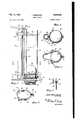
- FIG. 1 is a side elevational View of a ball seat fitting with the overflow pipe connected therewith and with the fiush valve mechanism attached to the ball seat and including a ball with means for lifting the same from its seat,
- Fig. 2 is a perspective view of the locking plate which is used for attaching the mechanism to the ball valve seat
- Figs. 3 and 4 are, respectively, transverse sectional views of the flush valve mechanism taken, respectively, on lines 3-3 and 4-4 of Fig. l,
- Fig. 5 is a fragmentary elevational view showing the connection of the operating handle with the upper end of the lift rod for the ball, the view being taken generally on line 5-5of Fig. l,
- Fig. 6 is a top plan view of the mechanism
- Fig. 7 is a fragmentary perspective view of the bottom of the lift rod and of the ring portion thereof adapted to be fitted about the ball to lift the same,
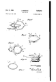
- Fig. 8 is a perspective view of a modified form of supporting annular structure wherein the attachment of the same is effected by disengagement of the ball seat member and lifting the same into place from the bottom of the ball seat member, the annular structure extending about the ball seat member more than 180,
- Fig. 9 is a top plan view of a ball seat member or fitting having integral lug portions for receiving the lower ends of the cage wires,
- Fig. 10 is a side elevational view of the ball seat member shown in Fig. 9 secured to the upper end of the outlet pipe.
- l5 represents the bottom of a flushtank into which there is extended an outlet pipe I6 and on the upper enel of which is a ball seat member
- the member l1 A has a round top seat surface 2
- the ball seat member l1 has a side projection 26 upwardly from which extends an overflow pipe 21.
- the bracket 28 is adjustable to Vary the extent to which the ball valve element 22 may be lifted.
- the rod ;24 has an adjustable bracket 33 thereon which is secured to the rod 24 by a set screw 34.
- This bracket 33 has an arm 35 with a downwardly bent hook and adapted to extend through any one of a series of holes 36 in the lever 25.
- the lower ends of the cage rods 32 are seated in lug portions 31 o-f a plate 38 adapted to be locked to the periphery of the member
- the member 42 has, on one end, a lug 31 in which is fashioned a recess 44 adapted to receive a hook formation 45 of the member 43, Figs. 2 and 4. Accordingly, there has been provided an annular ⁇ structure for supporting the cage rods 32 which can be extended about the ball seat member
- a modified form of the invention wherein the locking strncture, as indicated by reference character 41, is formed in one piece and is adapted to be tightly fitted over the neck portion 20 of the member I1, and is preferably composed of a. resilient material as for example bronze or corrosion-resisting steel.
- the member 41 is open throughout a small arc to extend to the opposite sides of portion 25.
- the member 41 has lug formations 48 integral therewith and a flange 49 extending from side lug 5
- lugs for supporting the lower ends of the rods 32 are, as indicated at 53, made integral with the valve seat member. These lugs preferably extend from a ring formation 54 surrounding the main part of the member. This member with the integral lugs and ring is indicated generally at 55. A portion 56 extends laterally for supporting the overflow pipe 21.
- the member 55 can be similarly attached to the threadedoutlet pipe i6 and secured by the same nut I9 upon the bottom of the tank. Both the members I1 and 55 have the threaded outlet pipe integral therewith. It is apparent, however, that the member could be formed with internal threads engage'able with a threaded outlet pipe portion.
- a 'flush valve construction comprisin'g 'a ball seat member having'a lateral extension, an overflow drain pipesupported on the lateral extension, Va cage rod supporting annular structure 'adapted to be releasab'ly secured to the ball seat member; said cage rod supporting structure including separable members with lug projections thereon; cage 'rods extending into the lug projections, and adjustable means connected to the upper end of the cage rods and adapted to be adjusted along the overflow drain pipe; one of said members having a recess, the other having a formation adapted to be extended into the recess; said members being adapted to partially extend above the ball seat member; and a locking wire adapted to be extended between the free ends of said members and over the lateral extension of the ball seat member to retain the members on the ball seat member against lateral displacement.
- a ush Valve supporting annular structure adapted to fit upon a valve seat member having a lateral projection member, and about the same comprising: a pair of arcuately-shaped portions and a wire 'member having downwardly bent terminal portions; said annular structure having an opening to permit the disposal of the same upon the Valve seat member without interference from said lateral projection; said arcuately-shaped portions having rst ends; each of said iirst ends having means for mutual hinged engagement; said arcuately-shaped portions also having second ends each having a hole therein; the downwardly bent terminal portions of said wire member being engageable in said holes, whereby said members are positively maintained about said valve lseat member.
Landscapes
- Health & Medical Sciences (AREA)
- Life Sciences & Earth Sciences (AREA)
- Engineering & Computer Science (AREA)
- Hydrology & Water Resources (AREA)
- Public Health (AREA)
- Water Supply & Treatment (AREA)
- Sanitary Device For Flush Toilet (AREA)
Description
J. BIRKMAIER Feb. 17, 1953 FLUSH VALVE 2 SHEETS-SHEET l Filed April 28, 1948 FLUSH VALVE Filed April 28, 1948 2 SHEETS-SHEET 2 BY @MK/M Patented Feb. 17, 1953 UNITED STATES PATENT OFFICE FLUSH VALVE John Birkmaier, Franklin Square, N. Y.
Application April 28, 1948, Serial No. 23,800
' 2 Claims.
This invention relates to ush valves or flush tanks. l
It is an object of the present invention to provide a detachable ball valve cage device which can be placed over a flush valve seat and retained thereon in a detachable manner wherein a simple retaining lock is had and the supporting plate annular structure becomes rigid with the valve seat fitting and can be applied thereover without interference from the overflow pipe which extends upwardly from the valve seat tting and wherein the cage and wires are positively retained at their lower ends to the valve seat fitting. y
Other objects of the present invention are to provide a flush valve mechanism for flush tanks which is of simple construction, inexpensive to manufacture, easy to install upon the outlet ball seat fitting of the flush tanks, and efficient in operation.
For other objects and for a better understanding of the invention, reference may be had to the following detailed description taken in connection with the accompanying drawing, in which Fig. 1 is a side elevational View of a ball seat fitting with the overflow pipe connected therewith and with the fiush valve mechanism attached to the ball seat and including a ball with means for lifting the same from its seat,
Fig. 2 is a perspective view of the locking plate which is used for attaching the mechanism to the ball valve seat,
Figs. 3 and 4 are, respectively, transverse sectional views of the flush valve mechanism taken, respectively, on lines 3-3 and 4-4 of Fig. l,
Fig. 5 is a fragmentary elevational view showing the connection of the operating handle with the upper end of the lift rod for the ball, the view being taken generally on line 5-5of Fig. l,
Fig. 6 is a top plan view of the mechanism,
Fig. 7 is a fragmentary perspective view of the bottom of the lift rod and of the ring portion thereof adapted to be fitted about the ball to lift the same,
Fig. 8 is a perspective view of a modified form of supporting annular structure wherein the attachment of the same is effected by disengagement of the ball seat member and lifting the same into place from the bottom of the ball seat member, the annular structure extending about the ball seat member more than 180,
Fig. 9 is a top plan view of a ball seat member or fitting having integral lug portions for receiving the lower ends of the cage wires,
Fig. 10 is a side elevational view of the ball seat member shown in Fig. 9 secured to the upper end of the outlet pipe.
Referring now lto Figures 1 to 7, l5 represents the bottom of a flushtank into which there is extended an outlet pipe I6 and on the upper enel of which is a ball seat member |1 having a bottom face I8 adapted to be secured against the bottom face by a nut I9 upon being elevated against the tank bottom. The member l1 Ahas a round top seat surface 2| for receiving ball valve element 22 about which extends a loop 23 of a. lift rod '24 extending upwardly for connection with a lift lever 25. The ball seat member l1 has a side projection 26 upwardly from which extends an overflow pipe 21. On this pipe 21 there is adjustably secured a bracket 28 having a plate portion 29 with lugs 3| thereon through which the upper ends of cage rods 32 are extended. The bracket 28 is adjustable to Vary the extent to which the ball valve element 22 may be lifted.
The rod ;24 has an adjustable bracket 33 thereon which is secured to the rod 24 by a set screw 34. This bracket 33 has an arm 35 with a downwardly bent hook and adapted to extend through any one of a series of holes 36 in the lever 25.
The lower ends of the cage rods 32 are seated in lug portions 31 o-f a plate 38 adapted to be locked to the periphery of the member |1 by a wire 39 having downwardly bent ends 4| adapted to fit in holes in the ends of separable members 42 and 43 forming the plate 38. The member 42 has, on one end, a lug 31 in which is fashioned a recess 44 adapted to receive a hook formation 45 of the member 43, Figs. 2 and 4. Accordingly, there has been provided an annular` structure for supporting the cage rods 32 which can be extended about the ball seat member |1 without having to disassemble the member I1 from the bottom of the flush tank. When it is desired to remove the structure 38 from the member l1, the wire 39 is lifted from the parts 42 and 43 and the hook end formation 45 is dropped out of the recess 44.
Referring to Fig. 8, there is shown a modified form of the invention wherein the locking strncture, as indicated by reference character 41, is formed in one piece and is adapted to be tightly fitted over the neck portion 20 of the member I1, and is preferably composed of a. resilient material as for example bronze or corrosion-resisting steel. The member 41is open throughout a small arc to extend to the opposite sides of portion 25. The member 41 has lug formations 48 integral therewith and a flange 49 extending from side lug 5| to the end faces of the member. In orde:l
3 to facilitate attachment of the member 41 with the member I 1, the same is forced over the periphery of the neck portion 20 of the member I1 until it is in a fully seated position, the member 41 being retained in its fully seated position by its resilient action.
In Figs. 9 and 10, there is shown a still further form of the invention wherein the lugs for supporting the lower ends of the rods 32 are, as indicated at 53, made integral with the valve seat member. These lugs preferably extend from a ring formation 54 surrounding the main part of the member. This member with the integral lugs and ring is indicated generally at 55. A portion 56 extends laterally for supporting the overflow pipe 21. The member 55 can be similarly attached to the threadedoutlet pipe i6 and secured by the same nut I9 upon the bottom of the tank. Both the members I1 and 55 have the threaded outlet pipe integral therewith. It is apparent, however, that the member could be formed with internal threads engage'able with a threaded outlet pipe portion.
It should now 4be apparent that there has been provided an annular 'structure for supporting cage 'rods which can be detachably connected to the valve Vseat member with little effort and in one form of vthe invention without having to remove the member from the tank bottom inorder to make the connection of the locking plate therewith. v
While various changes lmay be made in the detail construction, it will be understood that such changes shall be within the spirit and scope of the 'present invention as dened by the appended claims.
I claim:
1. A 'flush valve construction comprisin'g 'a ball seat member having'a lateral extension, an overflow drain pipesupported on the lateral extension, Va cage rod supporting annular structure 'adapted to be releasab'ly secured to the ball seat member; said cage rod supporting structure including separable members with lug projections thereon; cage 'rods extending into the lug projections, and adjustable means connected to the upper end of the cage rods and adapted to be adjusted along the overflow drain pipe; one of said members having a recess, the other having a formation adapted to be extended into the recess; said members being adapted to partially extend above the ball seat member; and a locking wire adapted to be extended between the free ends of said members and over the lateral extension of the ball seat member to retain the members on the ball seat member against lateral displacement.
2. A ush Valve supporting annular structure, adapted to fit upon a valve seat member having a lateral projection member, and about the same comprising: a pair of arcuately-shaped portions and a wire 'member having downwardly bent terminal portions; said annular structure having an opening to permit the disposal of the same upon the Valve seat member without interference from said lateral projection; said arcuately-shaped portions having rst ends; each of said iirst ends having means for mutual hinged engagement; said arcuately-shaped portions also having second ends each having a hole therein; the downwardly bent terminal portions of said wire member being engageable in said holes, whereby said members are positively maintained about said valve lseat member.
. A JOHN BIRKMA'IER.
REFERENCES CIT-ED The following references are of record in Athe file or this patent:
Priority Applications (1)
| Application Number | Priority Date | Filing Date | Title |
|---|---|---|---|
| US23800A US2628362A (en) | 1948-04-28 | 1948-04-28 | Flush valve |
Applications Claiming Priority (1)
| Application Number | Priority Date | Filing Date | Title |
|---|---|---|---|
| US23800A US2628362A (en) | 1948-04-28 | 1948-04-28 | Flush valve |
Publications (1)
| Publication Number | Publication Date |
|---|---|
| US2628362A true US2628362A (en) | 1953-02-17 |
Family
ID=21817266
Family Applications (1)
| Application Number | Title | Priority Date | Filing Date |
|---|---|---|---|
| US23800A Expired - Lifetime US2628362A (en) | 1948-04-28 | 1948-04-28 | Flush valve |
Country Status (1)
| Country | Link |
|---|---|
| US (1) | US2628362A (en) |
Cited By (4)
| Publication number | Priority date | Publication date | Assignee | Title |
|---|---|---|---|---|
| US2905949A (en) * | 1955-10-28 | 1959-09-29 | Valguard Company Inc | Flush valve assembly |
| US3842444A (en) * | 1973-05-21 | 1974-10-22 | H Gruenhagen | Bi-flush toilet apparatus |
| US3996629A (en) * | 1974-10-30 | 1976-12-14 | Riedel Rudolph T | Demand type flush tank control |
| US4858251A (en) * | 1987-11-17 | 1989-08-22 | Belaunde Alfredo De | Pressurized water cistern with floating valve |
Citations (8)
| Publication number | Priority date | Publication date | Assignee | Title |
|---|---|---|---|---|
| US1054940A (en) * | 1912-07-06 | 1913-03-04 | Albert S Rea | Flushing-valve. |
| US1237109A (en) * | 1917-02-07 | 1917-08-14 | Frank L Shoppe | Flush-tank valve. |
| US1515414A (en) * | 1923-05-02 | 1924-11-11 | Rockhill Benjamin Franklin | Valve mechanism |
| US1655894A (en) * | 1927-05-27 | 1928-01-10 | Walter D Davenport | Valve guide |
| US1799770A (en) * | 1930-05-29 | 1931-04-07 | Wegner Rudolph | Guide for flush-tank valves |
| US1926754A (en) * | 1932-05-20 | 1933-09-12 | Richard H Coney | Flush valve |
| US2189345A (en) * | 1939-08-23 | 1940-02-06 | Elmer E Hillegas | Flush-tank control |
| US2460114A (en) * | 1945-03-29 | 1949-01-25 | Warren B Zern | Tank flush ball and guide support |
-
1948
- 1948-04-28 US US23800A patent/US2628362A/en not_active Expired - Lifetime
Patent Citations (8)
| Publication number | Priority date | Publication date | Assignee | Title |
|---|---|---|---|---|
| US1054940A (en) * | 1912-07-06 | 1913-03-04 | Albert S Rea | Flushing-valve. |
| US1237109A (en) * | 1917-02-07 | 1917-08-14 | Frank L Shoppe | Flush-tank valve. |
| US1515414A (en) * | 1923-05-02 | 1924-11-11 | Rockhill Benjamin Franklin | Valve mechanism |
| US1655894A (en) * | 1927-05-27 | 1928-01-10 | Walter D Davenport | Valve guide |
| US1799770A (en) * | 1930-05-29 | 1931-04-07 | Wegner Rudolph | Guide for flush-tank valves |
| US1926754A (en) * | 1932-05-20 | 1933-09-12 | Richard H Coney | Flush valve |
| US2189345A (en) * | 1939-08-23 | 1940-02-06 | Elmer E Hillegas | Flush-tank control |
| US2460114A (en) * | 1945-03-29 | 1949-01-25 | Warren B Zern | Tank flush ball and guide support |
Cited By (4)
| Publication number | Priority date | Publication date | Assignee | Title |
|---|---|---|---|---|
| US2905949A (en) * | 1955-10-28 | 1959-09-29 | Valguard Company Inc | Flush valve assembly |
| US3842444A (en) * | 1973-05-21 | 1974-10-22 | H Gruenhagen | Bi-flush toilet apparatus |
| US3996629A (en) * | 1974-10-30 | 1976-12-14 | Riedel Rudolph T | Demand type flush tank control |
| US4858251A (en) * | 1987-11-17 | 1989-08-22 | Belaunde Alfredo De | Pressurized water cistern with floating valve |
Similar Documents
| Publication | Publication Date | Title |
|---|---|---|
| US2800231A (en) | Drain strainer | |
| US3460168A (en) | Drainage system for sinks,lavatories and the like | |
| US2890463A (en) | Sink strainer | |
| US4483024A (en) | Variable flush water closet | |
| US2628362A (en) | Flush valve | |
| US3468512A (en) | Self-contained drainplug | |
| US1753724A (en) | Automatic backwater valve | |
| US1613251A (en) | Plumbing fixture | |
| US2321176A (en) | Waste and overflow fitting | |
| US2892197A (en) | Flush valve | |
| US2817849A (en) | Flush tank valve control means | |
| US2832963A (en) | Flush tank valve | |
| US2678451A (en) | Toilet flush valve | |
| US2430765A (en) | Repair device for flush tanks | |
| US1832243A (en) | Float valve construction | |
| US2632182A (en) | Flush valve guide device | |
| US2907050A (en) | Magnetic flush valve | |
| US2625692A (en) | Flush tank lever attachment | |
| US2627608A (en) | Toilet ball valve actuating linkage | |
| US2018534A (en) | Fill pipe cap | |
| US2819471A (en) | Toilet flush valve control | |
| US1223534A (en) | Closet-tank flush-valve. | |
| US4660232A (en) | Toilet flush valve | |
| US3339211A (en) | Flush tank bulb linkage | |
| US1564122A (en) | Flush valve |