US2626705A - Film shipping case - Google Patents
Film shipping case Download PDFInfo
- Publication number
- US2626705A US2626705A US147666A US14766650A US2626705A US 2626705 A US2626705 A US 2626705A US 147666 A US147666 A US 147666A US 14766650 A US14766650 A US 14766650A US 2626705 A US2626705 A US 2626705A
- Authority
- US
- United States
- Prior art keywords
- reel
- case
- film
- springs
- flanges
- Prior art date
- Legal status (The legal status is an assumption and is not a legal conclusion. Google has not performed a legal analysis and makes no representation as to the accuracy of the status listed.)
- Expired - Lifetime
Links
- 239000000945 filler Substances 0.000 description 8
- 239000002184 metal Substances 0.000 description 6
- 238000000926 separation method Methods 0.000 description 4
- 238000005304 joining Methods 0.000 description 3
- 238000003466 welding Methods 0.000 description 3
- 238000010276 construction Methods 0.000 description 2
- 238000004519 manufacturing process Methods 0.000 description 2
- 241000565354 Fraxinus longicuspis Species 0.000 description 1
- 229910000639 Spring steel Inorganic materials 0.000 description 1
- 230000003466 anti-cipated effect Effects 0.000 description 1
- 238000005452 bending Methods 0.000 description 1
- 239000011111 cardboard Substances 0.000 description 1
- 239000000463 material Substances 0.000 description 1
- 238000000034 method Methods 0.000 description 1
- 230000004048 modification Effects 0.000 description 1
- 238000012986 modification Methods 0.000 description 1
- 239000000123 paper Substances 0.000 description 1
- 239000011087 paperboard Substances 0.000 description 1
- 238000003825 pressing Methods 0.000 description 1
- 230000000717 retained effect Effects 0.000 description 1
- 230000035939 shock Effects 0.000 description 1
- 125000006850 spacer group Chemical group 0.000 description 1
- 238000003860 storage Methods 0.000 description 1
Images

Classifications
-
- G—PHYSICS
- G03—PHOTOGRAPHY; CINEMATOGRAPHY; ANALOGOUS TECHNIQUES USING WAVES OTHER THAN OPTICAL WAVES; ELECTROGRAPHY; HOLOGRAPHY
- G03B—APPARATUS OR ARRANGEMENTS FOR TAKING PHOTOGRAPHS OR FOR PROJECTING OR VIEWING THEM; APPARATUS OR ARRANGEMENTS EMPLOYING ANALOGOUS TECHNIQUES USING WAVES OTHER THAN OPTICAL WAVES; ACCESSORIES THEREFOR
- G03B21/00—Projectors or projection-type viewers; Accessories therefor
- G03B21/14—Details
- G03B21/32—Details specially adapted for motion-picture projection
- G03B21/321—Holders for films, e.g. reels, cassettes, spindles
- G03B21/323—Cassettes
Definitions
- This invention relates to. a case and more specifically to a case in which reels of movie film are placed for shipping and storage.
- An object of myinvention is to provide an improved case which will protect the enclosed film and reels from damage due to denting of the container.
- Another object of my invention is to provide an improved case in which the reels of film are shock-mounted.
- Another object of my invention is to provide an improved case in which bending togetherof the reel flanges is resisted.
- Another object of my invention is to provide an improved case in which a number of reels may be carried without damaging contact with each other.
- a further object of my invention provides for a case in which reels of film may be transported without loosening of the film.
- a further object of the invention provides for a case in which both full and partly filled reels may be intermixed without disadvantage.
- a still further object of my invention provides for a case which is economical and simple in manufacture.
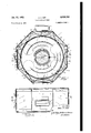
- Fig. 1 is a top view/of my container adapted to carry three reels;
- Fig. 2 is a sectional view taken on line II-II of Fig. 1;
- Fig. 3 is a sectional view taken on line III-III i'F aZ-" i Fig. 4 is. a. sectional view of a modification of mv cqntainer adapted to carry a ine l. t t n ein ake similarly to Fi 3. and
- Fig. 5 is an enlargement of a portion of'Fig. 4 and show a dent in u i e o a n r by a sharp instrument.
- my threeereel case comprises an upper section I and a lower section 2, connected by means of a link hinge 3 and provided with a lock 4.
- the upper section 1 is composed of sides 5 and extended portions 5 and I which carry parts of previously-mentioned lock 4 and hinge 3.
- Sides 5 and extensions 6 and l are preferably formed from a strip of sheet metal bent to the desired shape.
- End walls 8 are identical in size and shape and are extended and bent over to form flanges I 0 to which are welded sides 5 and extended sides 5 and 1.
- a carrying handle ll Attached to the uppermost side 5 is a carrying handle ll.
- Lock 4 is protected by guards l2 to prevent damage should the case be accidentally set down on the lock or should an externalobject contact
- the lower section 2 is composed of a sheet metal strip bent to form sides l3, and identical end walls M which are extended and bent over to form flanges l5 to which are welded sides l3.
- 3b also carry the lower part of hinge 3 at It, and side l3a carries part of lock 4 at ll.
- Attached by spot welding to the lowermost side [3 opposite handle I I is a base piece H! on which to rest the case.
- the inside of the case is lined with heavy paper or cardboard 20 to protect the reels from damage should they contact the walls or sides of the case.
- metal filler strips I9 project, one being spot welded to each of the sides 5 and I3 in order that springs hereinafter described may be firmly attached to the sides by spot welding to the strips.
- apertures could be made in the liner and the springs attached directly to the sides by weldingfriveting', or bolting. I'show welding through filler strips merely as a preferred method in "this'instancej Means is provided to hold the reels oi film separated from each other and without contact with the walls or sides of the case.
- such means consists of half-elliptical spring steel strips 2
- the ends Zlb remote from filler strips l9 are rolled or curved so that they may slide easily along theliner 20 as the springs 21 are flattened by pressure. With no such pressure present, each spring 2
- each group of springs mounted in side by side relationship forms a spring group and is hereinafter referred to as such.
- the number of springs in a group is, of course, equal to the number of reels to be contained in the case.
- a standard moving picture film reel comprises a hub 22 by means of which the reel is held on the projection machine, and parallel circular flanges 23 extending radially outward from the hub 22 and between which the film 24 is retained.
- the flanges 23 being large and supported only at the center, they may be easily bent inward with resultant damage to the film.
- the reel is constructed to allow a clearance space between the flanges and film.
- Figs. 4 and 5 I have shown a single-reel case similar in construction to the three-reel case previously described, the primary diiierences being that the filler strips and the sheet metal strips forming the sides are narrower than in the three reel case and only one spring is attached to each filler strip. That is, side extensions I311 and 13b in Figs. 4 and 5 and filler strips (hidden) are substantially one-third as wide as extensions Ba and [3b and filler strips I9 shown in Figs. 1, 2 and 3. Again, spaces 25 are provided between the reel and the case, so that the reel-film unit is supported only by springs 2
- a motion picture film reel and case of the class wherein a reel hastwo substantially parallel circular flanges supported by and extending radially outward from a hub, a film wound on said reel between said flanges, the case having two substantially parallel end walls of greater perimeter than said reel, a plurality of sides connected with and spacing said end walls, said case being divided adjacent a diameter of said reel into upper and lower sections, and means separably joining said sections, the combination with said case of a plurality of spring strips mounted one on the interior face of each of said sides and projecting along its associated side, each of said spring strips being of half-elliptical configuration convex inwardly to engage the periphery of said wound film and of a width less than the separation of the flanges of said reel butgreater than the width of said film, each of said spring strips attached to a side on one end and slidably engaging the same side on the'other end, whereby said flanges form a bridge between said hub and the unyielding dimension of said spring
- each reel has two substantially parallel circular flanges supported by and extending radially outward from a hub, a film wound on each reel between said flanges, a case having two substantially parallel end walls of greater perimeter than each reel, a plurality of sides connected with and spacing said end walls, said case being divided adjacent the, diameters of said reels into upper and lower sections, and means separably joining said sections, the combination with said case of a plurality of spring strips mounted in side-by-side relationship on the interior face of each of said sides projecting along said side, the number of said spring strips mounted on each of said sides being equal to the number of reels to be contained in said case, each of said spring strips being of halfelliptical configuration convex inwardly to engage the periphery of said wound film and of a width less than the separation of the flanges of each reel but greater than the width of said film, each of said spring strips attached to a side on one end and slidably
- a film reel having parallel circular flanges supported by and extending radially outward from a hub; film wound on said reel; a case having walls and containing said reel; inwardly directed spring strips on the inside of said case, all of said strips lying in a common plane; each strip being attached at one end to the inside of said case, being of half-elliptical configuration convex inwardly and extending between said fianges to engage said film, being slidably engaged with said case at its other end and being of a width less than the separation of the flanges of said reel but greater than the width of said film; whereby said spring strips-mount said reel in spaced relation to the walls of the case, prevent the flanges from pinching and damaging the film, and prevent the film from unwinding.
Landscapes
- Physics & Mathematics (AREA)
- General Physics & Mathematics (AREA)
- Storage Of Web-Like Or Filamentary Materials (AREA)
Description
Jan. 27, 1953 J, ASH 2,626,705
FILM SHIPPING CASE Filed March 4, 1950 2 SHEETSJSHEET 1 IN VEN TOR. Ji mv :1 Au:
y, Dmwn/ Jan. 27, .1953 J. J. AsH
FILM SHIPPING CASE 2 SHEETS-SHEET 2 Filed March 4, 1950 R WA mm. M J.
Patented Jan. 27, 1953 UNITED STATES PATENT OFF-ICE Claims.
This invention relates to. a case and more specifically to a case in which reels of movie film are placed for shipping and storage.
Reels of moving picture film must by necessity be frequently transported about the country from theater to theater and stored for considerable lengths of time. Such a film is quite valuable and much time and money lost if it is damaged. Often, due to rough handling in shipping, sharp objects dentthe cases and film s d y s to make the film practically useless; the flanges of the reels may be bent together and the film loosened from the reel by such treatment. Cases of present types are'entirely inadequate to guard the film and reels from this type of damage.
An object of myinvention is to provide an improved case which will protect the enclosed film and reels from damage due to denting of the container.
Another object of my invention is to provide an improved case in which the reels of film are shock-mounted.
Another object of my invention is to provide an improved case in which bending togetherof the reel flanges is resisted.
Another object of my invention is to provide an improved case in which a number of reels may be carried without damaging contact with each other.
A further object of my invention provides for a case in which reels of film may be transported without loosening of the film.
A further object of the invention provides for a case in which both full and partly filled reels may be intermixed without disadvantage.
A still further object of my invention provides for a case which is economical and simple in manufacture. e
Further objects and features of my invention will become apparent from the following description.
In the drawings, which illustrate two embodiments of my'invention. and in which like numerals refer to like parts throughout,
Fig. 1 is a top view/of my container adapted to carry three reels;
Fig. 2 is a sectional view taken on line II-II of Fig. 1;
Fig. 3 is a sectional view taken on line III-III i'F aZ-" i Fig. 4 is. a. sectional view of a modification of mv cqntainer adapted to carry a ine l. t t n ein ake similarly to Fi 3. and
Fig. 5 is an enlargement of a portion of'Fig. 4 and show a dent in u i e o a n r by a sharp instrument.
Referring to Figs. 1,, 2 and 3 my threeereel case comprises an upper section I and a lower section 2, connected by means of a link hinge 3 and provided with a lock 4.
The upper section 1 is composed of sides 5 and extended portions 5 and I which carry parts of previously-mentioned lock 4 and hinge 3. Sides 5 and extensions 6 and l are preferably formed from a strip of sheet metal bent to the desired shape. End walls 8 are identical in size and shape and are extended and bent over to form flanges I 0 to which are welded sides 5 and extended sides 5 and 1.
Attached to the uppermost side 5 is a carrying handle ll.
Lock 4 is protected by guards l2 to prevent damage should the case be accidentally set down on the lock or should an externalobject contact The lower section 2 is composed of a sheet metal strip bent to form sides l3, and identical end walls M which are extended and bent over to form flanges l5 to which are welded sides l3. Flanges l5 on side |3b also carry the lower part of hinge 3 at It, and side l3a carries part of lock 4 at ll. Attached by spot welding to the lowermost side [3 opposite handle I I is a base piece H! on which to rest the case.
The inside of the case is lined with heavy paper or cardboard 20 to protect the reels from damage should they contact the walls or sides of the case. Through the liner 20, metal filler strips I9 project, one being spot welded to each of the sides 5 and I3 in order that springs hereinafter described may be firmly attached to the sides by spot welding to the strips. It is to be understood that apertures could be made in the liner and the springs attached directly to the sides by weldingfriveting', or bolting. I'show welding through filler strips merely as a preferred method in "this'instancej Means is provided to hold the reels oi film separated from each other and without contact with the walls or sides of the case. In the preferred embodiment shown and described, such means consists of half-elliptical spring steel strips 2|, spot welded to filler strips I9 at ends 2m. The ends Zlb remote from filler strips l9 are rolled or curved so that they may slide easily along theliner 20 as the springs 21 are flattened by pressure. With no such pressure present, each spring 2| assumes the shape shown in dotted linesv on the lower side ii in Fig. 2.
In my multi-reel case, each group of springs mounted in side by side relationship (Fig. 3) forms a spring group and is hereinafter referred to as such. The number of springs in a group is, of course, equal to the number of reels to be contained in the case.
The reel and film shown in Figs. 2, 3, 4 and 5 form no part of my invention per se, and are shown only to illustrate the various features and advantages of my case.
A standard moving picture film reel comprises a hub 22 by means of which the reel is held on the projection machine, and parallel circular flanges 23 extending radially outward from the hub 22 and between which the film 24 is retained. The flanges 23 being large and supported only at the center, they may be easily bent inward with resultant damage to the film. The reel is constructed to allow a clearance space between the flanges and film.
In my invention I make the springs 2| of greater width than the film but less than the distance between the reel flanges. Thus, when a reel containing film is placed in my case, the springs fit between the reel flange and against the film. In efiect, the film is supported in the case by direct engagement with the springs, and so the film cannot unwind or loosen from the reel.
As shown in Fig. 3, I leave a space 25 between the several springs 2| of a spring group so that the reels are spaced from each other and individually supported. Thus there is no possibility of a reel being deformed by the weight of the others should the case be tipped over, nor can a shock be transmitted by contact between the reels.
In Figs. 4 and 5 I have shown a single-reel case similar in construction to the three-reel case previously described, the primary diiierences being that the filler strips and the sheet metal strips forming the sides are narrower than in the three reel case and only one spring is attached to each filler strip. That is, side extensions I311 and 13b in Figs. 4 and 5 and filler strips (hidden) are substantially one-third as wide as extensions Ba and [3b and filler strips I9 shown in Figs. 1, 2 and 3. Again, spaces 25 are provided between the reel and the case, so that the reel-film unit is supported only by springs 2|, and no art of the reel touches the case.
In Fig. 5 I have shown the end wall 14 of my single-reel case being dented by a sharp object 25. toward the reel but, due to the space 25 between reel and end wall M, the reel and film are not damaged. Were the blow even heavier, flanges 23 would still not damage the film because spring 2!, being wider than the film, acts as a spacer to keep the flanges from pinching together. The flanges 23 are thus bridged between the reel hub 22 and the unyielding dimension of springs 25.
In operation the weight of the film and reel pressing against springs 2| tends to flatten out the springs and causes the free end 21b of each spring to move along the paper-lined side 20. The springs on the vertical sides (Fig. 2) are ar ranged pointing downward, as are those on the slanting sides of the lower section 2. Thus when the reel is placed in the lower section, the springs slide with the reel rather than against it. Similarly, the springs on the slanting sides of the upper section I point upward. As the upper section is closed down on the reel and film, there is a minimum of friction between the film and springs. When the reel is not full, the springs would be flattened to a lesser degree, but the reel would still ride in approximately the same position in the case with each spring in contact with The heavy paper lining 20 is bent inward the film to prevent any loosening or unwinding.
I have shown and described my three-reel case merely to illustrate the features embodied in a multi-reel case, which can be made to hold two, three or more reels. Therefore, I do not limit my invention to the single and three-reel cases.
From the foregoing detailed description of two embodiments of my invention, it is apparent that I have provided an improved case which will effectively protect the films and reels from damage, each reel being individually suspended on springs thus protecting the film and reel as well as keeping the film wound tightly on the reel.
In the preferred embodiments of my case, I have constructed it principally of sheet metal because of each of manufacture, durability, and trength. However, it is to be understood that various parts could be constructed of material other than metal and in no sense do I limit myself to the metallic type of construction.
While I have made my case of octagonal shape, it is anticipated that it could be of various shapes. In the same sense, the number of springs provided is not limited.
Various changes in details and arrangement of parts can be made by one skilled in the art without departing from the spirit of my invention or the scope of the appended claims.
What I claim is:
1. In a motion picture film reel and case of the class wherein a reel hastwo substantially parallel circular flanges supported by and extending radially outward from a hub, a film wound on said reel between said flanges, the case having two substantially parallel end walls of greater perimeter than said reel, a plurality of sides connected with and spacing said end walls, said case being divided adjacent a diameter of said reel into upper and lower sections, and means separably joining said sections, the combination with said case of a plurality of spring strips mounted one on the interior face of each of said sides and projecting along its associated side, each of said spring strips being of half-elliptical configuration convex inwardly to engage the periphery of said wound film and of a width less than the separation of the flanges of said reel butgreater than the width of said film, each of said spring strips attached to a side on one end and slidably engaging the same side on the'other end, whereby said flanges form a bridge between said hub and the unyielding dimension of said springs when said reel is placed in said case, and whereby said spring strips resiliently mount the reel in spaced relation to said side and end Walls.
2. In motion picture film, reels and a case therefor of the class wherein each reel has two substantially parallel circular flanges supported by and extending radially outward from a hub, a film wound on each reel between said flanges, a case having two substantially parallel end walls of greater perimeter than each reel, a plurality of sides connected with and spacing said end walls, said case being divided adjacent the, diameters of said reels into upper and lower sections, and means separably joining said sections, the combination with said case of a plurality of spring strips mounted in side-by-side relationship on the interior face of each of said sides projecting along said side, the number of said spring strips mounted on each of said sides being equal to the number of reels to be contained in said case, each of said spring strips being of halfelliptical configuration convex inwardly to engage the periphery of said wound film and of a width less than the separation of the flanges of each reel but greater than the width of said film, each of said spring strips attached to a side on one end and slidably engaging the same side on the other end, whereby said flanges of each reel form a bridge between said hub and the unyielding dimension of said springs when said reel is placed in said case, and whereby said spring strips resiliently mount each reel in spaced relation to said side and end walls and to the other reels in said case.
3. A film case as set forth in claim 2, wherein said springs on the downwardly extending sides of said lower section are fastened at their upper ends and said springs on the downwardly extending sides of said upper section are fastened at their lower ends whereby to reduce friction between said film and springs when placing said reel in said case.
4. In combination, a film reel having parallel circular flanges supported by and extending radially outward from a hub; film wound on said reel; a case having walls and containing said reel; inwardly directed spring strips on the inside of said case, all of said strips lying in a common plane; each strip being attached at one end to the inside of said case, being of half-elliptical configuration convex inwardly and extending between said fianges to engage said film, being slidably engaged with said case at its other end and being of a width less than the separation of the flanges of said reel but greater than the width of said film; whereby said spring strips-mount said reel in spaced relation to the walls of the case, prevent the flanges from pinching and damaging the film, and prevent the film from unwinding.
5. In a motion picture film reel and case of the class wherein a reel has two substantially parallel circular flanges supported by and extending radially outward from a hub, said flanges being spaced apart to receive a film of predetermined width, the case having two substantially parallel end walls of greater perimeter than said reel, a plurality of sides connected with and spacing said end walls, said case being divided adjacent a diameter of said reel into upper and lower sections, and means separately joining said sections; the combination with said case of a plurality of spring strips mounted one on the interior face of each of said sides and projecting along its associated side, each of said spring strips being of half-elliptical configuration convex inwardly to engage the periphery of a film wound on said reel, said spring strips being of a width less than the separation of said flanges of said reel but greater than the predetermined width of the film, each of said spring strips being attached to a side on one end and having a distance from end to end of said spring less than the length of the associated side, whereby said flanges form a bridge between said hub and the unyielding dimension of said springs when said reel is placed in said case, and whereby said spring strips resiliently mount the reel in spaced relation to said side and end walls.
JOHN J. ASH.
REFERENCES CITED The following references are of record in the file of this patent:
UNITED STATES PATENTS France Oct. 25, 1906
Priority Applications (1)
| Application Number | Priority Date | Filing Date | Title |
|---|---|---|---|
| US147666A US2626705A (en) | 1950-03-04 | 1950-03-04 | Film shipping case |
Applications Claiming Priority (1)
| Application Number | Priority Date | Filing Date | Title |
|---|---|---|---|
| US147666A US2626705A (en) | 1950-03-04 | 1950-03-04 | Film shipping case |
Publications (1)
| Publication Number | Publication Date |
|---|---|
| US2626705A true US2626705A (en) | 1953-01-27 |
Family
ID=22522422
Family Applications (1)
| Application Number | Title | Priority Date | Filing Date |
|---|---|---|---|
| US147666A Expired - Lifetime US2626705A (en) | 1950-03-04 | 1950-03-04 | Film shipping case |
Country Status (1)
| Country | Link |
|---|---|
| US (1) | US2626705A (en) |
Cited By (8)
| Publication number | Priority date | Publication date | Assignee | Title |
|---|---|---|---|---|
| US2761555A (en) * | 1954-11-05 | 1956-09-04 | Thomas S Kulka | Tape retaining means for reels |
| US3209904A (en) * | 1963-09-10 | 1965-10-05 | Data Packaging Corp | Reel closure |
| DE1244572B (en) * | 1964-12-05 | 1967-07-13 | Probe & Develop Inc | Transport and storage container for film reels |
| US3552551A (en) * | 1969-03-05 | 1971-01-05 | Goldberg Brothers Inc | Film reel shipping case |
| US4732271A (en) * | 1985-12-20 | 1988-03-22 | Minnesota Mining And Manufacturing Company | Canister and light sealing, anti-blooming tab |
| USD381329S (en) * | 1995-11-14 | 1997-07-22 | Urlik Randall G | Film container |
| US6095453A (en) * | 1995-09-08 | 2000-08-01 | Technicolor, Inc. | Motion picture film platter system |
| US6976586B2 (en) | 2002-05-10 | 2005-12-20 | Asm America, Inc. | Delicate product packaging system |
Citations (4)
| Publication number | Priority date | Publication date | Assignee | Title |
|---|---|---|---|---|
| FR368960A (en) * | ||||
| US1192744A (en) * | 1915-02-10 | 1916-07-25 | Frank Melugin | Egg-case filler. |
| US1985615A (en) * | 1933-01-11 | 1934-12-25 | Scovill Manufacturing Co | Container |
| US2151025A (en) * | 1937-08-30 | 1939-03-21 | Jacob M Goldberg | Shipping case for moving-picture films |
-
1950
- 1950-03-04 US US147666A patent/US2626705A/en not_active Expired - Lifetime
Patent Citations (4)
| Publication number | Priority date | Publication date | Assignee | Title |
|---|---|---|---|---|
| FR368960A (en) * | ||||
| US1192744A (en) * | 1915-02-10 | 1916-07-25 | Frank Melugin | Egg-case filler. |
| US1985615A (en) * | 1933-01-11 | 1934-12-25 | Scovill Manufacturing Co | Container |
| US2151025A (en) * | 1937-08-30 | 1939-03-21 | Jacob M Goldberg | Shipping case for moving-picture films |
Cited By (8)
| Publication number | Priority date | Publication date | Assignee | Title |
|---|---|---|---|---|
| US2761555A (en) * | 1954-11-05 | 1956-09-04 | Thomas S Kulka | Tape retaining means for reels |
| US3209904A (en) * | 1963-09-10 | 1965-10-05 | Data Packaging Corp | Reel closure |
| DE1244572B (en) * | 1964-12-05 | 1967-07-13 | Probe & Develop Inc | Transport and storage container for film reels |
| US3552551A (en) * | 1969-03-05 | 1971-01-05 | Goldberg Brothers Inc | Film reel shipping case |
| US4732271A (en) * | 1985-12-20 | 1988-03-22 | Minnesota Mining And Manufacturing Company | Canister and light sealing, anti-blooming tab |
| US6095453A (en) * | 1995-09-08 | 2000-08-01 | Technicolor, Inc. | Motion picture film platter system |
| USD381329S (en) * | 1995-11-14 | 1997-07-22 | Urlik Randall G | Film container |
| US6976586B2 (en) | 2002-05-10 | 2005-12-20 | Asm America, Inc. | Delicate product packaging system |
Similar Documents
| Publication | Publication Date | Title |
|---|---|---|
| US2626705A (en) | Film shipping case | |
| US2015028A (en) | Holder for advertising material | |
| US20040206652A1 (en) | Welding wire container with ribbed walls and a mating retainer ring | |
| US3123204A (en) | Container | |
| US1992950A (en) | Packing of rotary cutters | |
| US3170590A (en) | Pail type shipping container | |
| US2174661A (en) | Castered harness | |
| US3601249A (en) | Cylindrical storage box with a lid, for diapositives in radially arranged compartments | |
| US3393798A (en) | Abrasive disk package | |
| US2822919A (en) | Protective reel band | |
| US2558839A (en) | Film reel carrying case | |
| US2912139A (en) | Drum stacking ring | |
| US2889921A (en) | Container for wire | |
| US2177152A (en) | Motion picture film reel | |
| US3379536A (en) | Pie crust package | |
| US1137126A (en) | Shipping-container for phonograph-records. | |
| US2997197A (en) | Shipping drum | |
| US2806590A (en) | Belt package | |
| US3170591A (en) | Pail type shipping container | |
| US3125215A (en) | Combined housing and retaining means | |
| US3341002A (en) | Packaging container | |
| US2477512A (en) | Shipping package | |
| US2037807A (en) | Baking pan unit | |
| US2546923A (en) | Shipping container with articlesupporting base | |
| US2067753A (en) | Fruit basket and liner therefor |