US2626541A - Stereotype plate finishing machine - Google Patents
Stereotype plate finishing machine Download PDFInfo
- Publication number
- US2626541A US2626541A US52323A US5232348A US2626541A US 2626541 A US2626541 A US 2626541A US 52323 A US52323 A US 52323A US 5232348 A US5232348 A US 5232348A US 2626541 A US2626541 A US 2626541A
- Authority
- US
- United States
- Prior art keywords
- saddle
- plate
- cutter
- cutters
- cutter bar
- Prior art date
- Legal status (The legal status is an assumption and is not a legal conclusion. Google has not performed a legal analysis and makes no representation as to the accuracy of the status listed.)
- Expired - Lifetime
Links
Images


Classifications
-
- B—PERFORMING OPERATIONS; TRANSPORTING
- B41—PRINTING; LINING MACHINES; TYPEWRITERS; STAMPS
- B41D—APPARATUS FOR THE MECHANICAL REPRODUCTION OF PRINTING SURFACES FOR STEREOTYPE PRINTING; SHAPING ELASTIC OR DEFORMABLE MATERIAL TO FORM PRINTING SURFACES
- B41D5/00—Working, treating, or handling stereotype plates
-
- Y—GENERAL TAGGING OF NEW TECHNOLOGICAL DEVELOPMENTS; GENERAL TAGGING OF CROSS-SECTIONAL TECHNOLOGIES SPANNING OVER SEVERAL SECTIONS OF THE IPC; TECHNICAL SUBJECTS COVERED BY FORMER USPC CROSS-REFERENCE ART COLLECTIONS [XRACs] AND DIGESTS
- Y10—TECHNICAL SUBJECTS COVERED BY FORMER USPC
- Y10T—TECHNICAL SUBJECTS COVERED BY FORMER US CLASSIFICATION
- Y10T409/00—Gear cutting, milling, or planing
- Y10T409/30—Milling
- Y10T409/306664—Milling including means to infeed rotary cutter toward work
- Y10T409/307448—Milling including means to infeed rotary cutter toward work with work holder
-
- Y—GENERAL TAGGING OF NEW TECHNOLOGICAL DEVELOPMENTS; GENERAL TAGGING OF CROSS-SECTIONAL TECHNOLOGIES SPANNING OVER SEVERAL SECTIONS OF THE IPC; TECHNICAL SUBJECTS COVERED BY FORMER USPC CROSS-REFERENCE ART COLLECTIONS [XRACs] AND DIGESTS
- Y10—TECHNICAL SUBJECTS COVERED BY FORMER USPC
- Y10T—TECHNICAL SUBJECTS COVERED BY FORMER US CLASSIFICATION
- Y10T409/00—Gear cutting, milling, or planing
- Y10T409/30—Milling
- Y10T409/306664—Milling including means to infeed rotary cutter toward work
- Y10T409/307784—Plural cutters
Definitions
- This invention relates to improvements in stereotype plate finishing machines and especially to an improved machine for milling tension lock-up pockets in the concave inner surfaces of stereotype plates.
- Such advantages of the machine of the present invention include improved apparatus for supporting a plate for sliding endwise movement'onto the saddle or support on which it is carried during the finishing operation; improved apparatus for machining fiat surfaces at the corners of one end of the plate; improved plate clamping apparatus for securing the plate on the' supporting saddle; improved apparatus for bringing the plat into registry so as to insure that the finishing operations are correctly correlated to the type on the plate; transparent guards for guarding the pocket cutters while permitting registry of the plate by register indicators projected through the transparent guards; improved cutter lubricating mechanism and mechanism permitting manual withdrawal of the cutters from the plate pockets when the ma-v chine is stopped.
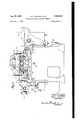
- Fig. l is a right side elevation of the machine with part of the housing structure in section;
- Fig. 2 is a left side elevation of the machine
- Fig. 3 is a sectional elevation of the machine taken along the line 3-3 of Fig.
- Fig. 4 is a rear end elevation of the machine takenalong the line 4-4 of Fig. 3;
- - Fig. 5 is a front end elevation of the machine, partly in section, taken along the line 55 of Fig. 3;
- Figs. 6 and 7 are sectional views taken, respectively, along the lines E-6 and 1-
- Figs. 8 and 9 are, respectively, sectional views of the side register cutter unit taken, respective- 1y, along the lines 8-8 and 99 of Fig. '7;
- Fig. 10 is a sectional view taken along the line l0l0 of Fig. 8;
- Fig. 11 is a sectional view taken along the line HIl of Fig. 1;
- Fig. 12 is asectional view taken along the line l2
- a stereotype plate A of generally semi-cylindrical form is carried on a cylindrical saddle l.
- the saddle l is journalled at each end by journal extensions 2 and 3, respectively, engaging bearings 4 and 5, which are secured to the main frame 6 of the machine.
- the saddle .I has longitudinal side openings X 2 11). Four cutters I are mounted on a cutter bar 8.
- the machine is powered by a motor 9. contained in a recess in the base of the main frame 6 on a support In which is adjustable by means of a turn buckle Hi to adjust the tension on the drive belts (Figs. 1, 3 and 4).
- Power is trans: mitted from'the motor 9 to the driven parts of the machine through V belts engaging a motor pulley II and a pulley 12 on a shaft [3.
- Each .of the cutters 1 is fixed tothe upper end of a vertically extending cutter spindle, IA journalled in the cutter bar I and drivenfro n the horizontal shaft l3 through bevel gears l5 and [6 (Fig. 11).
- Cutter bar 8 is pivoted to swing about a horizontal axis in the main frame by bearings 1 and 1" at its opposite ends.
- the cutter bar oscillates from side to side of the machine and extends its cutters 1 out through the saddle openings X and Y to engage the plate 'A and mill pockets therein.
- Oscillatory motion is imparted to the cutter bar 8 by a roller 1 carried by a crank arm l8 engaging a slot track l9 secured to the front end of the cutter bar 8 and extending radially of the axis about which the cutter bar oscillates (Fig. 3).
- crank arm [1 vis fixed to the inner end of a shaft 20 journalled within a tubular bearing 2
- a crank 24 is fixed to shaft 20 outside the bearing 2
- the shaft 20 may be manually turned slightly in order to move the cutters 1 out'of engagement with a plate A in the event the machine should stop while the cutters en gage a plate.
- the power mechanism which oscillates the shaft 20 includes a spring connection to be described which permits this manual movement of the cutter bar when the power drive is stationary.
- an adjustment ring 26 which is mounted to rotate in a shouldered recess in the outer surface of the fixed flange 22 of the bearing 2
- the ring 26 carries laterally projecting ears 2'! which fit into slots in guides 28 that are secured to the front end of the saddle l (Figs. 5 and 6).
- a cross shaft 29 journalled' in the saddle about the axis of its bearings without interfering with endwise reciprocation of the saddle during which the guides 28 slide. onthe ears 2'! of the ring 2'5.
- the inner end of the shaft 35 threadedly engages a tapped opening in the saddle'journal extension 3;
- The'adaptor 36 is pivotally connected to the bifurcated upper end of a lever 31 which moves the. saddle endwise during machine operation, as will be explained.
- crank'24 of the cutter bar oscillating shaft 2U' is pivotally connected to the upper end of connecting rod. 38. tubular. fitting .39 rotatably secured to a crank 59 fixed to the low speed shaft 4
- Two coiled springs 42- are. carried by the rod 38 on opposite sides. of the fitting 39 and their-outer ends engage collars 43 fixed tov the rod; With this arrangement L one: rotation of the shaft 4
- the shaft-4 is driven from the high speed shaft
- a barrel cam .48 is fixed to the rearward end of the shaft 4
- the lever 37 is pivoted toathe mainframe fiat 5.3.. Oscillation of the lever ST bythe cam. 48 slides. the saddle back and forth endwise of' the machine.
- the relation between the ,cutter bar oscillating drive and the plate saddle reciprocating drive is such that the cutter bar 3 is first moved to one the-saddle in the opposite direction.
- the cycle ends with the movement of the cutter bar to an intermediate position to withdraw the cutters 1 from the pockets last out and the operation of the-machine is stopped at this point by a motor deenergizing limit switch 52 operated by a cam 53 attached to the inner face of the barrel cam 48.
- a trough 54 is provided in the main frame beneath the cutter bar 8 and a conveyor screw 55
- the rod 33 slidably engages a 4 on the slow speed shaft 4
- a loading platform is provided at the front end of the machine and comprises a platform bracket 5? attached to the frame 6 by four shoulder screws 53 passing through vertically elongated slots in the bracket (Fig, 5).
- the upper portion of the platform bracket is provided with spaced parallel track grooves 59 for the reception of the side edges of a plate A..
- permits verticaladjustment of the platform bracket 51 so that a stereotype plate of predetermined dimensions; may slide directly from the platform onto the saddle coming too rest against the stops 82 secured to the saddle (Fig. i).
- This adjustable feature also permits lowering of the platform to. permit the milling of double length plates which overhang the endof the saddle when pockets are milled inthe opposite endthereof.
- the mechanism for clamping the plate, on the. saddle includes two brackets iitattachedtoeach side of the saddle and carrying pivots for the lower ends of four clamp sectors 64 (Figs. 1, 4, 5 and. 11).
- a clamp toggle B5 is pivotally secured tov the upper ends of the sector 64 on the left side of the machine, as viewed in Fig. 11, and each of the sectors til on the right hand side is pivotally secured to an eyev bolt. '55, the opposite. end of which is pivotally attached to the clamp. toggle 55 at 8?.
- the inner surfaces of the sectors 64 are lined with yielding material, such as leather stripping, cc; Th radius of the inner surface of this stripping E8 is slightly larger than the radius of the outer plate surface so thatwhen theclamp toggle 65 is closed, the sectors. 64 are flexed and put pressure on the plate at. all points where the stripping 66, contacts it.
- a stop projection 69 on. each sector 54. comes in contact with anabutment hi on. each bracket 63 when the clamp tog le 6:5 is opened, these parts acting as stops to limit thepivotal opening movement of each sector 64. This insures that each sector 64 moves substantially the same distance away. from the saddle i. as the oppositely disposed sector so that all sectors disengage the plate when the clamp toggle is opened.
- Each sector 64 carries a boss with a tapped hole therein to receive a thumb screw H.
- secure transparent guards 12 on, opposite sides of the saddl I over saddle openings X and Y.
- the guards 12 may be formed of suitable. transparent plastic material. They prevent injury to an operator if. the. machine operates without a plate A on the saddle I", in which. event theunp-rotected cutters extend through the openings X and Y..
- the guards 72 are transparent to permit the passage therethrough of light beams that project register images onto the plate, and the observation of such images and of register marks on the plate by the operator. In order to prevent clinging of stereotype plate.
- a plunger type lubricator T4 of known construction is secured to the machine Irame near one side of the rear end thereof, as shown in Figs. 2 and 4.
- the operating arm 75 of the lubricator which acts in a known manner to discharge a predetermined amount of lubricant through the flexible hose 15 each time it is oscillated, is disposed in the path of an arm i7 fixed to the lever 37 and'is oscillated thereby once in each cycle-of machine operation.
- hose I6 conducts the lubricant through a connector 18 secured to the rearward end of the saddle and a rigid tube 19 to four Ts 80, each of which is secured to the inside of the saddle I over one of the cutters 1 when the cutter bar 8 is in an intermediate position tilting toward the right sid of the saddle, as viewed in Fig. 4.
- Each T carries a metering nozzle M which directs lubricant onto the adjacent cutter I.
- the intermittent operation of the lubricator operating arm by the lever 31 is so timed that a limited amount of lubricant is ejected from the nozzles 8I when the cutters 1 are beneath these nozzles.
- a side register cutter unit E is provided, the construction and mounting of which are shown in Figs. 3, 7, 8, 9 and 10.
- the unit E includes a gear housing 82 with a dovetail extension 83 which slides in a slide plate 84 secured to the cutter bar 8 (Fig. 10).
- the gear housing 82 carries an extension 85 that extends within the cutter bar 8 and embraces the rearmost cutter spindle I4 (Fig. 8).
- Two end-face cutters 86 and 87 are rotatably carried by the housing 82 and are driven from the cutter spindle I4 through the gears 88, 89, 90 and 9
- the cutters 86 and 01 are so disposed that when the housing 82 is in position to eiiect engagement of the bevel gear 93 with the spindle carried bevel gear 94, the cutters 85 and 81 move to positions where they finish flats on the opposite sides of the plate ends when moved across the plate ends by the cutter bar 8.
- the flats thus finished are used to abut stops on the plate cylinder of a press and so accurately locatethe plate longitudinally of the cylinder.
- Openings 05 and 90 which are extensions of the openings X and Y, are provided at opposite sides of the saddle I to receive the cutters 86 and 8'! of the unit E, and guards 0'5 and 90 are removably attached to the saddle to guard the cutters as they swing through the openings.
- the unit E When longitudinal registry of the plate is not required, as when the plate is used for printing in one color, the unit E is moved downward on the slide plate 84 so as to disengage the bevel gear 93 from the bevel gear 95 and retract the cutters 80 and 81 to positions where they do not engage the plate A.
- This retracted and inoperative position of the unit E is illustrated by broken lines in Fig. 8.
- a screw 09 is rotatably carried by and fixed against axial movement in a block I03 fixed to the gear housing 82.
- Each slide bracket I04 may be locked against sliding movement along the rail I02 by clamp bolts I05.
- Each slide bracket I04 is adjustably movable along its rail by a screw I06 threadedly engaging an upwardly extending part of the slide bracket.
- Each screw I06 has an operating knob I08 and is rotatably mounted in but held against axial movement with respect to a bracket I01 fixed to therail I02.
- a scale I09 is secured to the rail I02 and permits setting of the bracket I04.
- An arcuate rack segment is fixed to each slide bracket I02 and extendsupwardly therefrom along an arc concentric with the plate A on the saddle I.
- a projector unit is carried by a bracket III which is slidably adjustable along each rack segment IIO.
- a pinion H2 operated by a knob II3 on a shaft II4 journalled in the bracket I I I engages the rack teeth of the segment IIO for moving the bracket and projector unit along the segment, and a clamp screw H5 threaded in an opening in the bracket engages the segment and fixes the bracket in its adjusted position.
- Each projector unit U includes a lamp H6 in a housing II? and a projection tube II8 having its axis aligned with the lamp filament.
- Cross hairs or other like indicator image-forming means are etched on the inner lens II9 of the tube H8 and the lenses are adjusted to project the image on the surface of the plate A.
- the projected light beam passes through the transparent guard 12 (Fig. 11).
- a scale I20 is provided along each rack segment I I0 and these, with the scales I09 on the rails H02, permit the operator to take readings of the projector unit settings for each plate series so that duplicate plates of one series can be accurately finished even after the projector units have been moved to finish a different series of plates.
- the operator With. a plate A clamped in place on the saddle I, the operator sets the projector units to the desired position-and brings theplate into registry by adjustment horizontally and circumferentially with the knobs 3-4 and 34.
- the motor 9 is then started and it brings the pocket cutter l and the side register unit cutters 86 and 87 up to speed as the shaft 4
- the cutters l are first carried from the starting position shown in full lines in Fig. 11 to positions in which they move out of the opening Yat the rightzside-of the machine, as viewed in.
- the side register unit E moves its cutter 3.1 to the position shown in broken lines in .Fig. '7.
- the barrel cam 48 moves thesaddle J and plate A to the right as viewed inFig. .3 for a distance appropriate to mill pockets of the desired length.
- the rearward end face of the platenear its corner comes in contact with the cutter 8'1 and a fiat surface is finished thereon.
- the shaft M moves the cutter bar 8 back through its central position, completing the finishing of the side register fiat by the cutter 87 (Fig. 7)..
- the cutter bar 8 moves to the left'side, as viewed in Figs. 7 and 11, causing the cutter 86 to finish a flat for side registry near the opposite corner of the plate, and moving the cutters 1 into the plate t start pockets in its opposite side, asshown in broken lines in Fig. 11.
- the barrel cam 48 which has held the saddle l stationary during this transverse movement of the cutters now moves the saddle I and plate .A to the left, as viewed in Fig. 3, back to its starting position to mill pockets of the desired length in the opposite side of the plate.
- the cycle is then ended by movement of the cutter bar 8 to a central position, whereupon the motor 9 is deener- .gized by the switch 52 operated by the cam 53.
- Duplicate plates .of the series are similarly finished, each being first brought into registry with the images projected by the units U which remain in the positions where they were when registered with the points I on the first plate A of the series (Fig. 12).. the unit E is retracted to inoperative position, .as has been explained.
- a stereotype plate finishing machine comprising in combination a frame, a horizontally extending cylindrical saddle carried on said frame and slidable axially thereon, said saddle having longitudinally extending side openings at circumferentially spaced points, means for releasably securing a substantially semi-cylindrical stereotype plate to said saddle with one end face of said plate extending across said openings, a .cutter bar journalled in said frame within said saddle to swing transversely of said saddle about an axis parallel to-the saddle axis, pocket cutters on said cutter bar, spindles in said cutter bar carrying said cutters and extending radially of the cutter bar axis, a cutter unit including a plate end finishing cutter carried by said cutter bar, and driving means for first swinging said cutter bar to one side of said saddle to move said pocket cutters through of said longitudinal saddle openings into contact with said plate and simultanecusly to swing said plate end finishing cutter through said opening into line with a corner of an end face of said plate, and then sliding said saddle longitudinally to
- a stereotype plate finishing machine comprising in combination a frame, a horizontally extending cylindrical saddle carried on said frame and slidable axially thereon, said saddle having longitudinally extending side openings at circumferen'tially spaced points, means for releasably securing a substantially semi-cylindrical stereotype plate to said'saddle with one end face of said plate extending across said openings, a
- cutter bar journalled in said frame within said lsaddle to swing transversely of said saddle about cutters through one of said longitudinal saddle openings into contact with said plate and simultaneously to swing said plate end finishing cutter through said opening into line with a corner of an end face of said plate and then sliding said :saddle longitudinally to bring said end face of said plate against said finishing cutter,:and adjustable means for retracting said cutter unit radially of said cutter bar to a position in which said plate end finishing cutter cannot contact said plate end face.
- A: stereotype plate finishing machine comprising in combination a frame, a cylindrical saddle carried by said frame and having at least v one longitudinally extending side opening therein, a milling cutter carried by said frame within said saddle, means for moving said cutter through said opening to cut a pocket in a plate carried by said saddle, means for releasably clamping a stereotype plate to said saddle including elongated members extending circumferentially of said saddle over said opening, and a guard plate extending over said saddle opening and secured to one of said clamp members.
- a stereotype plate finishing machine comprising in combination a frame, a cylindrical saddle carried by said frame and having at least one longitudinally extending side opening therein, a milling cutter carried by said frame within said saddle, means for moving said cutter through said opening to cut a pocket in a plate carried by said saddle, means for releasably clamping a stereotype plate to said saddle including elongated members extending circumferentially of said saddle over said opening, and a transparent guard plate secured to one of said clamp members and extending over said saddle opening.
- a stereotype plate finishing machine comprising in combination a frame, a cylindrical saddle carried by said frame and having at least one side opening therein, means for releasably securing a stereotype plate to said saddle in a position to extend over said opening, a milling cutter within said saddle, means for moving said cutter through said opening and into contact with a plate on said saddle, means for adjustably moving said saddle relative to said cutter, a transparent guard plate extending over said saddle opening, and a plurality of projector units secured to said frame each including means for projecting an image through said guard plate onto a stereotype plate on said saddle.
- a stereotype plate finishing machine comprising in combination a frame, a cylindrical saddle carried by said frame and having side openings therein, means for releasably securing a stereotype plate on said saddle in a position to extend over said openings, a milling cutter within said saddle, means for moving said cutter alternately through said openings and into contact with a plate on said saddle, means for adjustably moving said saddle relative to said outter, a transparent guard plate carried by said plate securing means'and extending over said saddle openings, a plurality of projector unit's secured to said frame on opposite sides of said saddle, each including means for projecting an image throughsaid guard plate onto a plate on said saddle, and means for adjustably moving said projector units longitudinally and circumferentially of said saddle.
- a stereotype plate finishing machine comprising in combination a-"frame, a cylindrical saddle carried by 'said frame and having side openings thereimmeans for releasably securing a stereotype plate on said saddle in a position to extend over said openings, a milling cutter within said saddle, means for moving said cutter alternately through said openings and into contact with a plate on saidsaddle, means for ad- 'justably moving said saddle relative to said cutter, a plurality-of projector units secured to said frame on opposite sides of said saddle, each including means for projecting an image ontoa plate on said saddle, and means for adjustably circumferentially of said saddle.
- a stereotype plate finishing machine comprising in combination a frame, a longitudinally extending cylindrical saddle carried by said frame and having two circumferentially spaced longitudinally extending openings therein, means for removably securing a stereotype plate on said saddle over said openings, a cutter bar journalled Within said saddle on an axis parallel to the axis of said saddle, a plurality of rotary cutters carried by said cutter bar, means to swing said cutter bar about its axis to move said cutters transversely of said saddle through said openings into contact with a plate on said saddle, a driving motor, a driving connection between said motor and said cutter bar including a yielding element, and means on said driving connection between said yielding element and said cutter bar for permitting manual movement of said cutter bar about its axis when said motor is stationary.
- a stereotype plate finishing machine comprising in combination a frame, a longitudinally extending cylindrical saddle carried by said frame and having two circumferentially spaced longitudinally extending openings therein, means for removably securing a stereotype plate on said saddle over said openings, a cutter bar journalled within said saddle on an axis parallel to the axis of said saddle, a plurality of rotary cutters car-- 1'1. riedby'said cutter bar, acrank connected to said cutter bar, a driving motor, a driving connection between said crank and said motor to reciprocate said crank and swing. said cutter bar about its axis transversely of. said saddle to move said cutters alternately through said openings into contact with a plate on said saddle, said driving. connection including a connecting.
Description
1-. 1 M505 4 6 R 6 5 a MNUQ E 6 m 7 Q 2 s rm 0 no! 9 5 .V
8 m MM Jan. 27, 1953 c RICARDS EI'AL STEREOTYPE PLATE FINISHING MACHINE Flled Oct. 1, 1948 0. L. R|ARDs ETAL STEREOTYPE PLATE FINISHING MACHINE Filed Oct. 1, 1948 e Sheets-Sheet 2' ommzs LR/CQ/PQS 5/00? TO/P/VEE/F6 P404 1. Tau/$0M INVENTORS BY @44 V 73W ATTORNEYS Jan. 27, 1953 c. L. RICARDS ETAL 2,
STEREOTYPE PLATE FINISHING MACHINE Filed Oct. 1, 1948 v s sheets-sheets ATTORNEYS 0. L. RICARDS ETAL STEREOTYP-E PLATE FINISHING MACHINE Jan 27, 1953 Filed Oct. 1, 194a 8 Sheets-Sheet 4 Jan. 27, 1953 c. L. RICARDS ETAL 2,626,541
STEREOTYPE PLATE FINISHING MACHINE Filed Oct. 1, 1948 8 Sheets-Sheet 5 ATTORNEYS Jan. 27, 1953 8 Sheets-Sheed'B Filed Oct. 1, 1948 INVENTORS ATTORNEYS Jan. 27', 1953 c. RICARDS ETAL STEREOTYPE PLATE FINISHING MACHINE 8 Sheets-Shet '7 Filed Oct. 1, 1948 G 5 w w z w w (BMW R555 A N R m MEMO MA u T m w W 0 L N I W f n. fl M MW M 5 P //,T "f C./. 17 9 M w w 0 0 w \m g y YT, W M A% W w /55E 7m FEM; 314M; ram,
ATTORNEYS Jan. 27, 1953 c. L. RICARDS ETAL 2,626,541
STEREOTYPE PLATE FINISHING MACHINE Filed Oct. 1, 1948 i 8 Sheets-$169158 (HA/PL 5 1. filC/I/PDS my lS/DOR TO/PNEERQ /04 m5 4 PHUL z. T011 /50/\/ INVENTORS BY gab Y BMW ATTORNEYS Patented Jan. 27, 1953 2,626,541 STEREOTYPE PLATE FINISHING MACHINE Charles L. Ricards, South Plainfield, Isidor Tornberg, Plainfield, and Paul L. Tollison, North Plainfield, N. J assignors to Wood Newspaper Machinery Corporation, Plainfield, N. J a corporation of Virginia Application October 1, 1948, Serial No. 52,323'
14 Claims.
This invention relates to improvements in stereotype plate finishing machines and especially to an improved machine for milling tension lock-up pockets in the concave inner surfaces of stereotype plates.
Particular advantages of the machine of the present invention include improved apparatus for supporting a plate for sliding endwise movement'onto the saddle or support on which it is carried during the finishing operation; improved apparatus for machining fiat surfaces at the corners of one end of the plate; improved plate clamping apparatus for securing the plate on the' supporting saddle; improved apparatus for bringing the plat into registry so as to insure that the finishing operations are correctly correlated to the type on the plate; transparent guards for guarding the pocket cutters while permitting registry of the plate by register indicators projected through the transparent guards; improved cutter lubricating mechanism and mechanism permitting manual withdrawal of the cutters from the plate pockets when the ma-v chine is stopped.
The invention will be best understood by reference to the accompanying drawings, in which- Fig. l is a right side elevation of the machine with part of the housing structure in section;
Fig. 2 is a left side elevation of the machine;
Fig. 3 is a sectional elevation of the machine taken along the line 3-3 of Fig.
Fig. 4 is a rear end elevation of the machine takenalong the line 4-4 of Fig. 3;
- Fig. 5 is a front end elevation of the machine, partly in section, taken along the line 55 of Fig. 3;
Figs. 6 and 7 are sectional views taken, respectively, along the lines E-6 and 1-| of Fig. 3;
Figs. 8 and 9 are, respectively, sectional views of the side register cutter unit taken, respective- 1y, along the lines 8-8 and 99 of Fig. '7;
Fig. 10 is a sectional view taken along the line l0l0 of Fig. 8;
Fig. 11 is a sectional view taken along the line HIl of Fig. 1; and
Fig. 12 is asectional view taken along the line l2|2 of Figs. 1 and 11.
Referring to Figs. 1, 2 and 3, a stereotype plate A of generally semi-cylindrical form is carried on a cylindrical saddle l. The saddle l is journalled at each end by journal extensions 2 and 3, respectively, engaging bearings 4 and 5, which are secured to the main frame 6 of the machine.
The saddle .I has longitudinal side openings X 2 11). Four cutters I are mounted on a cutter bar 8.
The machine is powered by a motor 9. contained in a recess in the base of the main frame 6 on a support In which is adjustable by means of a turn buckle Hi to adjust the tension on the drive belts (Figs. 1, 3 and 4). Power is trans: mitted from'the motor 9 to the driven parts of the machine through V belts engaging a motor pulley II and a pulley 12 on a shaft [3. Each .of the cutters 1 is fixed tothe upper end of a vertically extending cutter spindle, IA journalled in the cutter bar I and drivenfro n the horizontal shaft l3 through bevel gears l5 and [6 (Fig. 11). Cutter bar 8 is pivoted to swing about a horizontal axis in the main frame by bearings 1 and 1" at its opposite ends. The cutter bar oscillates from side to side of the machine and extends its cutters 1 out through the saddle openings X and Y to engage the plate 'A and mill pockets therein. Oscillatory motion is imparted to the cutter bar 8 by a roller 1 carried by a crank arm l8 engaging a slot track l9 secured to the front end of the cutter bar 8 and extending radially of the axis about which the cutter bar oscillates (Fig. 3). The crank arm" [1 vis fixed to the inner end of a shaft 20 journalled within a tubular bearing 2| slidably fitted within the journal extension 2 of the saddle l and secured to the machine frame by a flange 22 and bolts 23 (Figs. 3 and 5). A crank 24 is fixed to shaft 20 outside the bearing 2|, and the end of the shaft 20 is squared at 25 to receive a hand wrench or crank which may be inserted through an opening 25 in the platform bracket 51, as indicated at I26. The shaft 20 may be manually turned slightly in order to move the cutters 1 out'of engagement with a plate A in the event the machine should stop while the cutters en gage a plate. It is inadvisable to start the machine with the cutters engaging a plate and this arrangement enables the operator to avoid so starting the machine under load. The power mechanism which oscillates the shaft 20 includes a spring connection to be described which permits this manual movement of the cutter bar when the power drive is stationary.
Limited adjustment of the saddle I about the axis of its journals 2 and 3 for registry of a saddle carried plate is provided by an adjustment ring 26 which is mounted to rotate in a shouldered recess in the outer surface of the fixed flange 22 of the bearing 2| (Fig. 3) The ring 26 carries laterally projecting ears 2'! which fit into slots in guides 28 that are secured to the front end of the saddle l (Figs. 5 and 6). A cross shaft 29 journalled' in the saddle about the axis of its bearings without interfering with endwise reciprocation of the saddle during which the guides 28 slide. onthe ears 2'! of the ring 2'5.
Longitudinal adjustment of the saddle I for plate registry is provided for by a hand wheel 34 at the back end of the machine, The shaft 35- of this hand wheel is fixed against axial movement in an adaptor 36 which slidably fitted'within thesaddle journal extension 3 and keyed against 7 rotation with respect thereto, as shown in Fig; 3.
The inner end of the shaft 35 threadedly engages a tapped opening in the saddle'journal extension 3; The'adaptor 36 is pivotally connected to the bifurcated upper end of a lever 31 which moves the. saddle endwise during machine operation, as will be explained.
The crank'24 of the cutter bar oscillating shaft 2U'is pivotally connected to the upper end of connecting rod. 38. tubular. fitting .39 rotatably secured to a crank 59 fixed to the low speed shaft 4| Two coiled springs 42- are. carried by the rod 38 on opposite sides. of the fitting 39 and their-outer ends engage collars 43 fixed tov the rod; With this arrangement L one: rotation of the shaft 4| raises and lowers the connecting rod 38, and so. swings the cutter bar 8 first to one side of the. saddle and then to the other, thesprings 42 taking up the excess motion of the-crank when the outward movement of the; cutter bar is arrested by one of the adjustable stop/screws 5| (Figs. 4 and 11). Adjustment of the. screws 5i regulatesthe. depthto which pockets' aremilled in the plate A by the. cutters. T.
The shaft-4 is driven from the high speed shaft |3Ythrough the worm reduction gear train 4i445, 46,-4| (Fig. 6), the speed of the shaft 4| being sufficientlyreduced from that of the shaft l3 that asingle revolution of the shaft 4| completes one plate finishing cycle of the machine. A barrel cam .48 is fixed to the rearward end of the shaft 4|. Acam follower 49 on the lower end of lever 31 engages.- the ca-m 4.8., The lever 37 is pivoted toathe mainframe fiat 5.3.. Oscillation of the lever ST bythe cam. 48 slides. the saddle back and forth endwise of' the machine.
The relation between the ,cutter bar oscillating drive and the plate saddle reciprocating drive is such that the cutter bar 3 is first moved to one the-saddle in the opposite direction. The cycle ends with the movement of the cutter bar to an intermediate position to withdraw the cutters 1 from the pockets last out and the operation of the-machine is stopped at this point by a motor deenergizing limit switch 52 operated by a cam 53 attached to the inner face of the barrel cam 48.
A trough 54 is provided in the main frame beneath the cutter bar 8 and a conveyor screw 55 The rod 33 slidably engages a 4 on the slow speed shaft 4| carries plate chips from this trough into a removable chip pan 56.
A loading platform is provided at the front end of the machine and comprises a platform bracket 5? attached to the frame 6 by four shoulder screws 53 passing through vertically elongated slots in the bracket (Fig, 5). The upper portion of the platform bracket is provided with spaced parallel track grooves 59 for the reception of the side edges of a plate A.. A screw 69 threaded into the bearing 4 and provided with a stop nut 6| permits verticaladjustment of the platform bracket 51 so that a stereotype plate of predetermined dimensions; may slide directly from the platform onto the saddle coming too rest against the stops 82 secured to the saddle (Fig. i). This adjustable feature also permits lowering of the platform to. permit the milling of double length plates which overhang the endof the saddle when pockets are milled inthe opposite endthereof.
The mechanism for clamping the plate, on the. saddle includes two brackets iitattachedtoeach side of the saddle and carrying pivots for the lower ends of four clamp sectors 64 (Figs. 1, 4, 5 and. 11). A clamp toggle B5 is pivotally secured tov the upper ends of the sector 64 on the left side of the machine, as viewed in Fig. 11, and each of the sectors til on the right hand side is pivotally secured to an eyev bolt. '55, the opposite. end of which is pivotally attached to the clamp. toggle 55 at 8?. The inner surfaces of the sectors 64 are lined with yielding material, such as leather stripping, cc; Th radius of the inner surface of this stripping E8 is slightly larger than the radius of the outer plate surface so thatwhen theclamp toggle 65 is closed, the sectors. 64 are flexed and put pressure on the plate at. all points where the stripping 66, contacts it. A stop projection 69 on. each sector 54. comes in contact with anabutment hi on. each bracket 63 when the clamp tog le 6:5 is opened, these parts acting as stops to limit thepivotal opening movement of each sector 64. This insures that each sector 64 moves substantially the same distance away. from the saddle i. as the oppositely disposed sector so that all sectors disengage the plate when the clamp toggle is opened.
Each sector 64 carries a boss with a tapped hole therein to receive a thumb screw H. The thumb screws 7| secure transparent guards 12 on, opposite sides of the saddl I over saddle openings X and Y. The guards 12 may be formed of suitable. transparent plastic material. They prevent injury to an operator if. the. machine operates without a plate A on the saddle I", in which. event theunp-rotected cutters extend through the openings X and Y.. The guards 72 are transparent to permit the passage therethrough of light beams that project register images onto the plate, and the observation of such images and of register marks on the plate by the operator. In order to prevent clinging of stereotype plate. metal to the cutters 7, means are provided for applying a small amount of lubricant to each cutter at one point in each operating cycle. A plunger type lubricator T4 of known construction is secured to the machine Irame near one side of the rear end thereof, as shown in Figs. 2 and 4. The operating arm 75 of the lubricator, which acts in a known manner to discharge a predetermined amount of lubricant through the flexible hose 15 each time it is oscillated, is disposed in the path of an arm i7 fixed to the lever 37 and'is oscillated thereby once in each cycle-of machine operation. The
hose I6 conducts the lubricant through a connector 18 secured to the rearward end of the saddle and a rigid tube 19 to four Ts 80, each of which is secured to the inside of the saddle I over one of the cutters 1 when the cutter bar 8 is in an intermediate position tilting toward the right sid of the saddle, as viewed in Fig. 4. Each T carries a metering nozzle M which directs lubricant onto the adjacent cutter I. The intermittent operation of the lubricator operating arm by the lever 31 is so timed that a limited amount of lubricant is ejected from the nozzles 8I when the cutters 1 are beneath these nozzles.
Particularly in multi-color printing, it is important that one end of each plate shall have flat surfaces finished to precise dimensions with respect to the type thereon in orderto maintain proper side register between plates in a color series. For this purpose a side register cutter unit E is provided, the construction and mounting of which are shown in Figs. 3, 7, 8, 9 and 10.
The unit E includes a gear housing 82 with a dovetail extension 83 which slides in a slide plate 84 secured to the cutter bar 8 (Fig. 10). The gear housing 82 carries an extension 85 that extends within the cutter bar 8 and embraces the rearmost cutter spindle I4 (Fig. 8). Two end- face cutters 86 and 87 are rotatably carried by the housing 82 and are driven from the cutter spindle I4 through the gears 88, 89, 90 and 9|, and a shaft 02 and bevel gears 93 and 94.- The cutters 86 and 01 are so disposed that when the housing 82 is in position to eiiect engagement of the bevel gear 93 with the spindle carried bevel gear 94, the cutters 85 and 81 move to positions where they finish flats on the opposite sides of the plate ends when moved across the plate ends by the cutter bar 8. The flats thus finished are used to abut stops on the plate cylinder of a press and so accurately locatethe plate longitudinally of the cylinder. Openings 05 and 90, which are extensions of the openings X and Y, are provided at opposite sides of the saddle I to receive the cutters 86 and 8'! of the unit E, and guards 0'5 and 90 are removably attached to the saddle to guard the cutters as they swing through the openings.
When longitudinal registry of the plate is not required, as when the plate is used for printing in one color, the unit E is moved downward on the slide plate 84 so as to disengage the bevel gear 93 from the bevel gear 95 and retract the cutters 80 and 81 to positions where they do not engage the plate A. This retracted and inoperative position of the unit E is illustrated by broken lines in Fig. 8. A screw 09 is rotatably carried by and fixed against axial movement in a block I03 fixed to the gear housing 82. The
threaded lower end of the screw 09 engages a tapped opening in a block IOI fixed to the slide plate 84. Operation of the screw 99 moves the unit E between its operative and retracted positions.
When the machine is employed to finish plates for multi-color printing, it is important that the plate pockets formed by the cutters I and which are engaged by plate clamping mechanism on the purpose means are provided for-projecting indicator marks onto the outer surface of the plate whereby each plate in the series can be moved by adjustment of the saddle I-to a position where register marks (which are cast with the type or otherwise fixed with relation to the type during manufacture of the plate) are aligned with the projected indicator marks.
Four indicator units U are disposed at points respectively adjacent the four corners of a plate These units are ad carries two slide brackets I04 adjacent its op posite ends. Each slide bracket I04 may be locked against sliding movement along the rail I02 by clamp bolts I05. Each slide bracket I04 is adjustably movable along its rail by a screw I06 threadedly engaging an upwardly extending part of the slide bracket. Each screw I06 has an operating knob I08 and is rotatably mounted in but held against axial movement with respect to a bracket I01 fixed to therail I02. A scale I09 is secured to the rail I02 and permits setting of the bracket I04. An arcuate rack segment is fixed to each slide bracket I02 and extendsupwardly therefrom along an arc concentric with the plate A on the saddle I. A projector unit is carried by a bracket III which is slidably adjustable along each rack segment IIO. A pinion H2 operated by a knob II3 on a shaft II4 journalled in the bracket I I I engages the rack teeth of the segment IIO for moving the bracket and projector unit along the segment, and a clamp screw H5 threaded in an opening in the bracket engages the segment and fixes the bracket in its adjusted position.
Each projector unit U includes a lamp H6 in a housing II? and a projection tube II8 having its axis aligned with the lamp filament. Cross hairs or other like indicator image-forming means are etched on the inner lens II9 of the tube H8 and the lenses are adjusted to project the image on the surface of the plate A. The projected light beam passes through the transparent guard 12 (Fig. 11). A scale I20 is provided along each rack segment I I0 and these, with the scales I09 on the rails H02, permit the operator to take readings of the projector unit settings for each plate series so that duplicate plates of one series can be accurately finished even after the projector units have been moved to finish a different series of plates.
Since there are several points of possible lost motion in the mechanism that reciprocates the saddle I longitudinally of the plate axis, means are provided for taking up all of this motion in the same direction at the time the machine is at rest and a plate is being adjusted for registry. This position of rest is illustrated in Fig. 3 where the saddle I is in its extreme left-hand position. Two pins I2I are respectively carried in horizontal openings I23 at diametrically opposite points in saddle bearing 4 at the front end of the machine. Springs I22 surround these pins and are compressed between shoulders on the pins and shoulder sleeves in the openings so as to force the pins to the right as viewed in Fig. 3 and against the end of the saddle I, taking up all lost motion in one direction when the saddle is adjusted by the knobs 3| and 34 to bring a plate into registry. Shoulders at the rearward ends of the openings limit the outward movement of the pins I21 by engagement with the pin shoulders.
With. a plate A clamped in place on the saddle I, the operator sets the projector units to the desired position-and brings theplate into registry by adjustment horizontally and circumferentially with the knobs 3-4 and 34. The motor 9 is then started and it brings the pocket cutter l and the side register unit cutters 86 and 87 up to speed as the shaft 4| begins to turn slowly. As the shaft 4| turns, the cutters l are first carried from the starting position shown in full lines in Fig. 11 to positions in which they move out of the opening Yat the rightzside-of the machine, as viewed in.
thatyfigure, and start to mill pockets in that side of the :plate. At the same time, the side register unit Emoves its cutter 3.1 to the position shown in broken lines in .Fig. '7. During the dwell of the cutters in this tilted position, the barrel cam 48 moves thesaddle J and plate A to the right as viewed inFig. .3 for a distance appropriate to mill pockets of the desired length. ,At the same time the rearward end face of the platenear its corner comes in contact with the cutter 8'1 and a fiat surface is finished thereon. Continued rotation of the shaft M moves the cutter bar 8 back through its central position, completing the finishing of the side register fiat by the cutter 87 (Fig. 7).. Then the cutter bar 8 moves to the left'side, as viewed in Figs. 7 and 11, causing the cutter 86 to finish a flat for side registry near the opposite corner of the plate, and moving the cutters 1 into the plate t start pockets in its opposite side, asshown in broken lines in Fig. 11. The barrel cam 48 which has held the saddle l stationary during this transverse movement of the cutters now moves the saddle I and plate .A to the left, as viewed in Fig. 3, back to its starting position to mill pockets of the desired length in the opposite side of the plate. The cycle is then ended by movement of the cutter bar 8 to a central position, whereupon the motor 9 is deener- .gized by the switch 52 operated by the cam 53.
Duplicate plates .of the series are similarly finished, each being first brought into registry with the images projected by the units U which remain in the positions where they were when registered with the points I on the first plate A of the series (Fig. 12).. the unit E is retracted to inoperative position, .as has been explained.
We claim:
1. YA stereotype plate finishing machine com.-
prising in combination a frame, .a cylindrical saddle carried on said frame and .having longitudinally extending side openings at circumterentially spaced points therein, means for re- .leasably securing a stereotype plate on said saddle over part of said openings, a cutter bar ,iournalled .in said frame to swing about an axis parallel to the axis of said saddle, rotary pocket milling cutters carried by said cutter bar eccentrically of its axis, means to swing said outter bar to move said cutters alternately through said openings and into engagement with a plate on said saddle, and plate end cutters carried .by said cutter bar adjacent one end of said plate and movable with said cutter bar through parts of said openings into alternate engagement with opposite portions of an end face of said plate.
.2. .A stereotype plate finishing .m'ach-ine comprising in combination a frame, a cylindrical saddle carried on said frame and having longitudinally extending side openings .at circum- If end registry is not required,
8-: ferentially spaced .points therein, means .for re-. leasably securing a stereotype plate on said saddle over part of said openings, a cutter bar journalled in said frame to swing about an axis parallel to the axis of said saddle, rotary pocket milling cutters carried by said cutter bar eccentrically of its axis, means to swing said outter bar to move said cutters alternately through said openings and .into engagement with a plate on said saddle, a cutter unit carried by said cutter bar adjacent one end thereof and adjustably movable radially of the cutter bar axis, and cutters on said cutter unit movable with said cutter bar through .said saddle openings into alternate engagement with oppositecorners of an end face of said plate.
3.. .Astereotype plate finishing machine com-' prising in combination a frame, a cylindrical saddle carried on said frame and having longitudinally extending side openings at circumferentialiy spaced points therein, means for releasably securing a stereotype plate on said saddle over part of said openings, a cutter bar journalled in said frame to swing about an axis parallel to the axis of said saddle, rotary pocket milling cutters carried by said cutter bar eccentrically of its axis, means to swing said cutter bar to move said cutters alternately through said openings and into engagement with a plate on said saddle, a cutter unit carried by said cutter bar at one end thereof, cutters on said unit movable with said cutter bar through said saddle openings into alternate engagement with opposite corners of an end face of said plate, a driving connection between said cutter unit cutters and said cutter bar cutters including separaole gears, and means for adjustably moving said cut-ter unit on said cutter bar radially of the cutter bar axis for retracting said cutter unit cutters from engagement with said plate and simultaneously separating said separable gears to break said driving connection.
4. A stereotype plate finishing machine comprising in combination a frame, a horizontally extending cylindrical saddle carried on said frame and slidable axially thereon, said saddle having longitudinally extending side openings at circumferentially spaced points, means for releasably securing a substantially semi-cylindrical stereotype plate to said saddle with one end face of said plate extending across said openings, a .cutter bar journalled in said frame within said saddle to swing transversely of said saddle about an axis parallel to-the saddle axis, pocket cutters on said cutter bar, spindles in said cutter bar carrying said cutters and extending radially of the cutter bar axis, a cutter unit including a plate end finishing cutter carried by said cutter bar, and driving means for first swinging said cutter bar to one side of said saddle to move said pocket cutters through of said longitudinal saddle openings into contact with said plate and simultanecusly to swing said plate end finishing cutter through said opening into line with a corner of an end face of said plate, and then sliding said saddle longitudinally to bring said end face of said plate against said end finishing cutter.
5. A stereotype plate finishing machine comprising in combination a frame, a horizontally extending cylindrical saddle carried on said frame and slidable axially thereon, said saddle having longitudinally extending side openings at circumferen'tially spaced points, means for releasably securing a substantially semi-cylindrical stereotype plate to said'saddle with one end face of said plate extending across said openings, a
cutter bar journalled in said frame within said lsaddle to swing transversely of said saddle about cutters through one of said longitudinal saddle openings into contact with said plate and simultaneously to swing said plate end finishing cutter through said opening into line with a corner of an end face of said plate and then sliding said :saddle longitudinally to bring said end face of said plate against said finishing cutter,:and adjustable means for retracting said cutter unit radially of said cutter bar to a position in which said plate end finishing cutter cannot contact said plate end face.
- 6. A: stereotype plate finishing machine comprising in combination a frame, a cylindrical saddle carried by said frame and having at least v one longitudinally extending side opening therein, a milling cutter carried by said frame within said saddle, means for moving said cutter through said opening to cut a pocket in a plate carried by said saddle, means for releasably clamping a stereotype plate to said saddle including elongated members extending circumferentially of said saddle over said opening, and a guard plate extending over said saddle opening and secured to one of said clamp members.
7. A stereotype plate finishing machine comprising in combination a frame, a cylindrical saddle carried by said frame and having at least one longitudinally extending side opening therein, a milling cutter carried by said frame within said saddle, means for moving said cutter through said opening to cut a pocket in a plate carried by said saddle, means for releasably clamping a stereotype plate to said saddle including elongated members extending circumferentially of said saddle over said opening, and a transparent guard plate secured to one of said clamp members and extending over said saddle opening.
8. A stereotype plate finishing machine comprising in combination a frame, a cylindrical saddle carried by said frame and having at least one side opening therein, means for releasably securing a stereotype plate to said saddle in a position to extend over said opening, a milling cutter within said saddle, means for moving said cutter through said opening and into contact with a plate on said saddle, means for adjustably moving said saddle relative to said cutter, a transparent guard plate extending over said saddle opening, and a plurality of projector units secured to said frame each including means for projecting an image through said guard plate onto a stereotype plate on said saddle.
9. A stereotype plate finishing machine comprising in combination a frame, a cylindrical saddle carried by said frame and having side openings therein, means for releasably securing a stereotype plate on said saddle in a position to extend over said openings, a milling cutter within said saddle, means for moving said cutter alternately through said openings and into contact with a plate on said saddle, means for adjustably moving said saddle relative to said outter, a transparent guard plate carried by said plate securing means'and extending over said saddle openings, a plurality of projector unit's secured to said frame on opposite sides of said saddle, each including means for projecting an image throughsaid guard plate onto a plate on said saddle, and means for adjustably moving said projector units longitudinally and circumferentially of said saddle.
10. A stereotype plate finishing machine comprising in combination a-"frame, a cylindrical saddle carried by 'said frame and having side openings thereimmeans for releasably securing a stereotype plate on said saddle in a position to extend over said openings,a milling cutter within said saddle, means for moving said cutter alternately through said openings and into contact with a plate on saidsaddle, means for ad- 'justably moving said saddle relative to said cutter, a plurality-of projector units secured to said frame on opposite sides of said saddle, each including means for projecting an image ontoa plate on said saddle, and means for adjustably circumferentially of said saddle.-
11. A stereotype plate finishing machine coin- -prising in combination a frame, a cylindrical saddle having a longitudinal opening therein carried by said frame, means for adjustably moving said saddle axially and circumferentially relative to said frame, means for releasably securing a stereotype plate on said saddle over said opening, at least one milling cutter carried by said frame within said saddle, means for moving said cutter transversely of said saddle through said opening into contact with a plate on said saddle, a plurality of elongated projector unit supports secured to said frame adjacent said saddle and extending circumferentially of said saddle in spaced relation thereon, a projector unit carried by each of said supports and including means for projecting an image onto the surface of a plate on said saddle, means for adjustably moving said projector units along said supports and a scale on each support for indicating the circumferential position of the projector unit thereon.
12. A stereotype plate finishing machine comprising in combination a frame, a longitudinally extending cylindrical saddle carried by said frame and having two circumferentially spaced longitudinally extending openings therein, means for removably securing a stereotype plate on said saddle over said openings, a cutter bar journalled Within said saddle on an axis parallel to the axis of said saddle, a plurality of rotary cutters carried by said cutter bar, means to swing said cutter bar about its axis to move said cutters transversely of said saddle through said openings into contact with a plate on said saddle, a driving motor, a driving connection between said motor and said cutter bar including a yielding element, and means on said driving connection between said yielding element and said cutter bar for permitting manual movement of said cutter bar about its axis when said motor is stationary.
13. A stereotype plate finishing machine comprising in combination a frame, a longitudinally extending cylindrical saddle carried by said frame and having two circumferentially spaced longitudinally extending openings therein, means for removably securing a stereotype plate on said saddle over said openings, a cutter bar journalled within said saddle on an axis parallel to the axis of said saddle, a plurality of rotary cutters car-- 1'1. riedby'said cutter bar, acrank connected to said cutter bar, a driving motor, a driving connection between said crank and said motor to reciprocate said crank and swing. said cutter bar about its axis transversely of. said saddle to move said cutters alternately through said openings into contact with a plate on said saddle, said driving. connection including a connecting. rod and means connected through springs. to reciprocate said connecting, rod and means connected to said .saddle. having an. opening therein, bearings supporting. said saddle on' said frame. for reciprocatory movement axially of said saddle, means for securing a stereotype" plate on said saddle over said opening, a plurality of cutters Within said saddle, means for moving said cutters transversely of. said saddle through said opening into contact with a plate on said saddle, driving means connected to said saddle to reciprocate said saddle axially, register means. carried by said frame ad- 12 jacent. said saddle for registry with points on a plate carried by said saddle, means for adjustably moving said saddle axially relative to said driving means, and resilient means interposed between said frame and said saddle for taking up slack in said driving connection in one direction.
CHARLES L. RICARDS. ISIDOR TORNBERG. PAUL L. TOLLISON'.
REFERENCES CITED The following references are of record in the file. of this. patent:
UNITED STATES PATENTS Number Name Date 1,511,141 Scott et al. Oct. 7, 1924 1,627,153 Deye et al. May 3, 1927 1,865,927 Lambert July 5, 1932 1,876,248 Krebs Sept. 6, 1932 2,100,461 Watson et al. Nov. 30, 1937 2,299,852 Shaner et al Oct. 27, 1942 2,322,129 Hawkins June 15, 1943 2,425,580 Tornberg et a1 Aug. 12, 1947 2,537,604 Ricards et al. Jan. 9, 1951
Priority Applications (2)
| Application Number | Priority Date | Filing Date | Title |
|---|---|---|---|
| US52323A US2626541A (en) | 1948-10-01 | 1948-10-01 | Stereotype plate finishing machine |
| US149556A US2670662A (en) | 1948-10-01 | 1950-03-14 | Stereotype plate finishing machine |
Applications Claiming Priority (1)
| Application Number | Priority Date | Filing Date | Title |
|---|---|---|---|
| US52323A US2626541A (en) | 1948-10-01 | 1948-10-01 | Stereotype plate finishing machine |
Publications (1)
| Publication Number | Publication Date |
|---|---|
| US2626541A true US2626541A (en) | 1953-01-27 |
Family
ID=21976848
Family Applications (1)
| Application Number | Title | Priority Date | Filing Date |
|---|---|---|---|
| US52323A Expired - Lifetime US2626541A (en) | 1948-10-01 | 1948-10-01 | Stereotype plate finishing machine |
Country Status (1)
| Country | Link |
|---|---|
| US (1) | US2626541A (en) |
Cited By (3)
| Publication number | Priority date | Publication date | Assignee | Title |
|---|---|---|---|---|
| US2706325A (en) * | 1952-12-06 | 1955-04-19 | William F Begley | Undercutting unit for printing plate |
| DE1108708B (en) * | 1955-01-19 | 1961-06-15 | Jorgen Bech | Vacuum clamping device for semi-cylindrical stereotype plates on machines for processing stereotype plates |
| US3192833A (en) * | 1963-06-06 | 1965-07-06 | Edward W Carroll | Milling machine for cutting air vents in glass molds |
Citations (9)
| Publication number | Priority date | Publication date | Assignee | Title |
|---|---|---|---|---|
| US1511141A (en) * | 1922-05-27 | 1924-10-07 | Matilda J Dill | Extension table for machine tools |
| US1627153A (en) * | 1924-05-06 | 1927-05-03 | Erwin G Deye | Device for use with routing mills |
| US1865927A (en) * | 1922-08-31 | 1932-07-05 | Lambert Gustaf Paul | Measuring device for workholders |
| US1876248A (en) * | 1926-12-16 | 1932-09-06 | Packard Motor Car Co | Metal working machine |
| US2100461A (en) * | 1935-10-11 | 1937-11-30 | Us Rubber Prod Inc | Apparatus for cutting tire molds |
| US2299852A (en) * | 1938-09-03 | 1942-10-27 | Wood Newspaper Mach Corp | Lubricator mechanism |
| US2322129A (en) * | 1939-12-06 | 1943-06-15 | Paul S Hawkins | Router |
| US2425580A (en) * | 1943-11-04 | 1947-08-12 | Wood Newspaper Mach Corp | Registering and trimming of printing plates |
| US2537604A (en) * | 1946-09-10 | 1951-01-09 | Wood Newspaper Mach Corp | Stereotype plate finishing machine |
-
1948
- 1948-10-01 US US52323A patent/US2626541A/en not_active Expired - Lifetime
Patent Citations (9)
| Publication number | Priority date | Publication date | Assignee | Title |
|---|---|---|---|---|
| US1511141A (en) * | 1922-05-27 | 1924-10-07 | Matilda J Dill | Extension table for machine tools |
| US1865927A (en) * | 1922-08-31 | 1932-07-05 | Lambert Gustaf Paul | Measuring device for workholders |
| US1627153A (en) * | 1924-05-06 | 1927-05-03 | Erwin G Deye | Device for use with routing mills |
| US1876248A (en) * | 1926-12-16 | 1932-09-06 | Packard Motor Car Co | Metal working machine |
| US2100461A (en) * | 1935-10-11 | 1937-11-30 | Us Rubber Prod Inc | Apparatus for cutting tire molds |
| US2299852A (en) * | 1938-09-03 | 1942-10-27 | Wood Newspaper Mach Corp | Lubricator mechanism |
| US2322129A (en) * | 1939-12-06 | 1943-06-15 | Paul S Hawkins | Router |
| US2425580A (en) * | 1943-11-04 | 1947-08-12 | Wood Newspaper Mach Corp | Registering and trimming of printing plates |
| US2537604A (en) * | 1946-09-10 | 1951-01-09 | Wood Newspaper Mach Corp | Stereotype plate finishing machine |
Cited By (3)
| Publication number | Priority date | Publication date | Assignee | Title |
|---|---|---|---|---|
| US2706325A (en) * | 1952-12-06 | 1955-04-19 | William F Begley | Undercutting unit for printing plate |
| DE1108708B (en) * | 1955-01-19 | 1961-06-15 | Jorgen Bech | Vacuum clamping device for semi-cylindrical stereotype plates on machines for processing stereotype plates |
| US3192833A (en) * | 1963-06-06 | 1965-07-06 | Edward W Carroll | Milling machine for cutting air vents in glass molds |
Similar Documents
| Publication | Publication Date | Title |
|---|---|---|
| US2626541A (en) | Stereotype plate finishing machine | |
| US3017828A (en) | Doctor blade mechanism | |
| US3073074A (en) | Work handling mechanism for rotary grinder | |
| US2111784A (en) | Honing machine | |
| US2537604A (en) | Stereotype plate finishing machine | |
| US2158237A (en) | Make-ready and proof machine | |
| US2670662A (en) | Stereotype plate finishing machine | |
| US2934864A (en) | Belt-grinding machine | |
| US3098435A (en) | Proof press for curved printing plates | |
| US1269239A (en) | Machine for finishing and cooling stereotype-plates. | |
| US2179211A (en) | Form grinding apparatus | |
| US1416462A (en) | Grinding machine | |
| US2425580A (en) | Registering and trimming of printing plates | |
| US736939A (en) | Grinding apparatus. | |
| US1872041A (en) | Grinding machine | |
| US1467525A (en) | Broaching machine | |
| US2204523A (en) | Plate registering machine | |
| US1481437A (en) | Broaching | |
| US1580343A (en) | Grinding machine | |
| US558641A (en) | ensign | |
| US2857716A (en) | Grinding apparatus | |
| US3304811A (en) | Hand saw grinder | |
| US1903149A (en) | Cam grinding apparatus | |
| US1785164A (en) | Multiple-stereotype-plate-casting machine | |
| US2797094A (en) | Sheet feeding and registering mechanism |