US2626507A - Apparatus for controlling refrigerating systems - Google Patents
Apparatus for controlling refrigerating systems Download PDFInfo
- Publication number
- US2626507A US2626507A US74586A US7458649A US2626507A US 2626507 A US2626507 A US 2626507A US 74586 A US74586 A US 74586A US 7458649 A US7458649 A US 7458649A US 2626507 A US2626507 A US 2626507A
- Authority
- US
- United States
- Prior art keywords
- pressure
- passageway
- space
- temperature
- valve
- Prior art date
- Legal status (The legal status is an assumption and is not a legal conclusion. Google has not performed a legal analysis and makes no representation as to the accuracy of the status listed.)
- Expired - Lifetime
Links
Images


Classifications
-
- F—MECHANICAL ENGINEERING; LIGHTING; HEATING; WEAPONS; BLASTING
- F25—REFRIGERATION OR COOLING; COMBINED HEATING AND REFRIGERATION SYSTEMS; HEAT PUMP SYSTEMS; MANUFACTURE OR STORAGE OF ICE; LIQUEFACTION SOLIDIFICATION OF GASES
- F25B—REFRIGERATION MACHINES, PLANTS OR SYSTEMS; COMBINED HEATING AND REFRIGERATION SYSTEMS; HEAT PUMP SYSTEMS
- F25B49/00—Arrangement or mounting of control or safety devices
- F25B49/02—Arrangement or mounting of control or safety devices for compression type machines, plants or systems
Definitions
- This invention relates generally to method and apparatus for controlling refrigerating systems and is an improvement upon my copending application, Serial No. 750,947 filed May 28, 1947, for Control Mechanism.
- An object of this invention is to provide a new and improved method of and apparatus for controlling the operation of refrigerating systems.
- Another object of this invention is to provide such a system in which thecontrolling apparatus is governed at least in part by the temperature of the refrigerated space.
- Another object of this invention is to provide such a refrigerating system in which the operation of the compressor is controlled by means of the temperature of the enclosed space.
- Another object of this invention is to provide in such a system means for maintaining the operation of the compressor continuous.
- Another object of this invention is to provide a new and improved control apparatus for use with the refrigerating system.
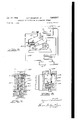
- Figure 1 is a diagrammatic view of a refrigerating system embodying the invention and showing the control apparatus in enlarged central vertical section;
- Fig. 2 is a view showing the temperature control dial for use with the control apparatus
- Fig. 3 is substantially a quarter section view showing a modified control apparatus for use in the system of Fig. l;
- Fig. 4 is a view taken substantially along the line 4-4 of Fig. 3;
- Fig. 5 is a view in central vertical section showing a still further modified form of control apparatus for use in the system of Fig. 1;
- Fig. 6 is a schematic view of a modified form of refrigerating systems embodying a modified form of the control apparatus
- Fig. 7 is a view in substantially vertical central section of the control elements of Fig. 6;
- Fig. 8 is a view in central vertical section of the working cylinder illustrated in Fig. 6 which positions the speed controlling element;
- Fig. 9 is a view similar to Fig. 7 but showing a modified form of control apparatus in which the working cylinder is fabricated integrally with the control apparatus;
- Fig. 10 is a view taken substantially along the line I0-
- Fig. 11 is a view in quarter section showing a still further modified form of the control apparatus for use in the system of Fig. 6;
- Fig. 12 is a view taken substantially along the line l2-I2 of Fig. 11.
- the invention contemplates a refrigerating system comprising the usual compressor l condenser 2, receiver 4, flow controlling device 6, and evaporator 8, all arranged in series circuit in the usual manner whereby heat laden low pressure vaporous refrigerant is compressed in the compressor I and discharged into the condenser 2 where it gives up heat to a surrounding medium, which may be the surrounding air, and condenses into a liquidwhich flows into the receiver 4.
- Liquid refrigerant flows from' the receiver under control of the device 6, which is herein shown to be a thermostatic expansion valve but may be of other common types, into the evaporator 8 where it vaporizes thereby abstracting heat from the space Ill to be refrigerated.
- the invention contemplates the continuous operation of the compressor l but at a speed which is just sufiicient to withdraw enough of the heat laden refrigerant vapors to maintain a predetermined desired temperature in the refrigerated space It]. As will be brought out later this temperature may be constant or may vary somewhat with change in the amount of heat required to be removed by the evaporator 8.
- the compressor l is powered by means of a gasoline engine I 2 through the medium of an endless belt
- a throttle I6 of the engine [2 controls its speed.
- the position of the throttle IS in turn is controlled by means of a control apparatus generally designated l8 having a temperature feeler bulb 20 located at suitable location in the space It].
- the apparatus [8 acts to open the throttle l6 thereby increasing the speed of the engine l2 whereby the compressor I will act to withdraw a greater quantity of refrigerant from the evaporator 8 to cause the evaporator to extract more heat from the space l0 and conversely.
- the apparatus [8 comprises generally a governing portion 22 and a working portion 24 which may be integral as shown in Fig. l or the governing portion may be separate as shown in Figs. 3 and and associated with a separate working portion as shown in Fig. 8.
- the portion 22 comprises a pair of end-to-end arranged hollow housing sections 26 and 28 suitably held together.
- a housing section 36 forms an end sectiorrfor the governing portion 22 and also forms the housing for the working portion 24,
- Section 28 is provided with a cross wall 32 which has a passageway 34 opening centrally and outwardly of said wall 32 toward the section 26 and which passageway is communicatively connected by means ofa small bore conduit 36 with the interior or" the bulb 20.
- the wall 32 is provided with a circular shoulder 38 to which is secured'one end of a flexible bellows member 46.
- the other end of the bellows member 49 is closed by a cap 42 having an outwardly facing circular shoulder 44.
- An annular ring 46 seats against the shoulder 44 and is held thereto by means of a helical com pression spring 48.
- the spring 48 extends toward an end wall 56 of the housing section 26 and seats against a shoulder on a threaded collar 52 held against rotation by one or more pins 53 slidably received in apertures in the wall 56.
- the wall 56 is provided with a bearing aperture 54 extending completely therethrough.
- a threaded adjusting member 56 extends completely through the aperture 54 and is provided with a peripheral shoulder 58 which seats against the wall 56.
- the external screw threads-66 mate with complementary internal threads of the collar 52 so that when the member 56 is rotated by the calibrated adjusting knob 62 the tension on the spring 48 may be regulated.
- the housing section 36 is'provided with a chamber 63 having a cylindrical bore portion 64 at its lower end in which is positioned a piston a 66.
- a piston rod 68 is secured at one end to the piston 66 and extends outwardly of the section 36 through its cover '10.
- the section 36 is also rwided with a side wall 12 which acts as an end wall for the housing section 28.
- the wall 12 is provided with an aperture 14 extending therethrough and in which is positioned a sleeve 16 forming at its opening into the chamber 63 a valve seat 18.
- a valve member 86 is slidably received within the member 16 and has a valve head 82 which is cooperable.
- valve member 86 intermediate the head 82 and a side wall opening in the sleeve 16 communicating with the passageway 86 is ofreduced diameter while the endportion thereof away from the head 82 is of 'normaldiameter to slidably fit within the bore of the sleeve 16 for guiding the'member 86.
- the member 80 extends outwardly of the wall 12 and is threadedly secured to a plate member 88.
- a bellows 90 is provided in order to prevent the escape to atmosphere of the fluid which escapes between the sleeve I6 and member 86 .
- the bellows 96 is preferably concentrically arranged relative to the member 80 and is sealed at one end to a dished member 92 clamped between the sections 28 and 36 and at its other end to the plate member 88.
- a plurality of push rods 94 are each secured at one end portion thereof to the plate member 88 and extend outwardly therefrom through apertures in the wall 32 and are secured at their other end portion to the ring 46.
- a bellows 96 concentrically arranged relative to the piston 66 and having one end sealed to the piston 66 and its other end sealed to an annular member 98 clamped between the cover 16 and the body portion of the section 36.
- the piston rod 68 is provided with a shoulder I I which engages the underside of the cover 16 to limit outward movement of the rod 66 and piston 66 under the influence of spring I62 positioned within the bore portion 64 intermediate the end wall thereof and the piston 66.
- a port I04 is provided in the piston for permitting a regulated flow of fluid past the piston and back to the evaporator 8, such flow being through a'passageway I06 and a conduit I63.
- the passageway I06 not only connects with the bore portion 64 but also with the space between the dished member 92 and end wall 12 whereby this space and the portion of the bore portion 64 beneath the piston 66 will be maintained at the same pressure as that in the evaporator 8.
- a forcetransmitting means such as the cable H6 connects the rod 68 to the throttle I6 and acts upon inward movement of the piston 66 into the portion 64 to open the throttle I6 which is continually urged toward closed position by the spring I I2.
- high pressure refrigerant vapor is discharged from the compressor I into the condenser 2 wherein it is condensed into a liquid which flows to the receiver 4.
- Liquid from the receiver 4 flows under control of the thermostatic valve 6 to the evaporator 8 whereby the high pressure liquid is reduced in pressure to that of the evaporator 8 after which it evaporates removing heat from the space If].
- the heat laden vapor is removed by the compressor I and discharged into the condenser 2 for recirculation in the manner described.
- the rate at which heat is removed from the evaporator 8 will be a function of the speed of operation of the compressor which speed is controlled by means of the apparatus l8.
- the temperature within the refrigerated space is above that desired and the pressure of the fluid within the'bulb 26 has increased to increase the pressure inthe chamber surrounded by the bellows 46 so that the end wall or cap 42 thereof has moved outwardly against the force exerted by the spring 48 causing the pins 64 to move the plate member 88 outwardly thereby moving the head portion 82 of the valve 66 into a position to close off fluid flow through the valve ports I8.
- the temperature of the space I8 decreases, the temperature of and the pressure within the bulb 28 decreases reducing the pressure in the chamber surrounded by the bellows 48 permitting the spring 48 to compress the bellows 48, thereby moving the pins 94 and plate member 88 to the right as viewed in Fig. 1.
- This causes the valve member 88 to open the valve port I8 permitting a predetermined flow of high pressure fluid from the receiver 4 through the conduit 84 and passageway 86 into the chamber 63 above the piston 86. Since the port I84 is of restricted flow capacity, the pressure in the chamber 83 will increase causing the piston 88 to move downwardly and cause the cabl I I8 to move the throttle I8 toward closed position against the force of the spring H2.
- the temperature of the bulb 28 falls to a predetermined minimum reducing the pressure within the bellows 48 and permitting the spring 48 to move the valve member 8 to its open position in which the pressure differential maintained across the piston 66 is that required to move the piston 88 to its inwardly-most position and the throttle I8 toward minimum fuel flow position.
- the com pressor I will then be operating at minimum speed and moving a minimum amount of heatladen vapor from the evaporator 8.
- control knob 82 may be calibrated as shown in Fig. 2, so that rotation thereof in accordanc with the calibration will visually indicate to the operator the approximate temperature at which the space I8 will be maintained.
- the apparatus I8 would operate to provide a substantially constant temperature within the space I8. Since, however, this force is not the only force, the temperature within the space I8 may increase slightly with increasing ambient temperatures. This increase results from the fact that as the ambient temperature surrounding the space I8 increases, more heat will leak into the space I8 and in order to remove this increased heat an increased difierential in temperature between the evaporator 8 and the interior of the space I8 is necessary. A decrease in evaporator pressure in reflected in a corresponding decrease in pressure in the bellows 98. Such lowering of this pressure increases the pressure required to be placed in the bellows 40 to move the valve 88 toward closed position to increase the compressor speed.
- the control apparatus I8 which is actuated by temperature of the space I8 and pressure of the evaporating refrigerant within the evaporator 8 for regulating the capacity of the compressor I, also provides means for controlling the capacity of the compressor so that as the temperature within the space increases away from the desired or set temperature for any reason the capacity of the compressor to remove heat is increased to provide what may be called an increasing'recovery factor. Conversely, as the actual space temperature approaches the desired or set temperature the recovery factor may decrease so that the temperature in the space is not lowered below the desired temperature.
- the rate of change in the recovery factor is to a large extent determined by the relative areas of the bellows 48 and 98, the rate of increase in exerted force of the spring 48 due to a collapsing thereof and the rate of change in fluid flow through the valve port I8 with movement of the valve member 88.
- the recovery factor should be high so that the temperature of the space will be brought to the desired temperature as rapidly as possible. In such event slight increases in temperature of the bulb 28 should provide for relatively great changes in fluid flow through the port I8 and the area of the bellows 98 should be small so that any lowering of the evaporator pressure will not tend to close the port 18.
- the invention provides for operating a refrigerating system with any desired rate of recovery and further for operating the system to prevent the temperature of the space from being lowered below the desired temperature.
- FIG. 3 which shows a modified form of the control mechanism or apparatus I8a
- this apparatus I8a may be substituted for the governing portion 22 of Fig. 1, and in such event, a separate working portion or cylinder 24a such as shown in Fig. 8 would be associated therewith for controlling the engine throttle IS.
- the apparatus I8a distinguishes from the apparatus I8 in that the working portion 24 of the apparatus I8 has been removed and a casing section 30a has been substituted therefor.
- the casing 30a comprises means to close the opposite end of the casing section 25 from that closed by the casing section 25a and is provided with an inlet passageway 85a adapted to be connected to receive high pressure vapor from the receiver 4 for controlling flow therefrom to the passageway I20 which may be connected in fluid flow relation with the portion of the chamber 53a above the piston 56a, Fig. 8.
- the poppettype valve 80 has been replaced by a sleeve-type valve 80a which is reciprocal within a sleeve 16a carried Within the casing section 30a.
- the sleeve 16a is provided with radial passageways aligned respectively with the passageway 80a and the passageway I20.
- the valve 80a is provided with a circumferential groove or slot I22 which with the valve 80a in one position aligns itself with the radial passageways of the sleeve 16a and which is movable outwardly of this aligned position to restrict and finally to out oif flow of fluid from the passageways 86a to the passageway I20.
- a the valve 80a moves under control of the bellows 400., the flow of high pressure fluid from the receiver 4 to the working cylinder 24a is controlled substantially in the same manner as the fluid flow was controlled by the apparatus I8 upon movement of the valve member 80.
- the section 30a is provided with a branch passageway I24 (Fig. 3) which communicates with the passageway Ia connected to the evaporator by means of conduit I08a.
- the passageway I20 is arranged to be communicatively connected to an inlet port I25 of the working cylinder 24a.
- FIG. 5 there is shown a still further modified form of apparatus IBb which may be used in place of the apparatus I8a and which comprises housing sections I50 and I52 between which there is clamped a plate member I54.
- the housing section I52 contains the valve member b having the head 82b for controlling the flow of high pressure vapor from the inlet passageway 86b to the outlet passageway I20b.
- the valve member 80b is concentrically positioned within a sleeve 15b and has its upper end threadedly secured to a cap member I55.
- the platelike member I54 has a central aperture therethrough through which the valve member 801; extends.
- a bellows 90b is arranged concentric to the valve member 80b and is sealed at its lower end to the platelike member I54 and at its upper end to the cap member I55.
- a passageway 341) within the plate I 54 opens upwardly therefrom exterior to the bellows 90b and within a second bellows 40b which is also arranged concentrically with the bellows 90b.
- the bellows 90b is sealed at its lower end to the plate member I54 outwardly of the opening of the passageway 341) and sealed at its upper end to the cap member I56.
- Fig. 6 there is shown a refrigerating system having a gasoline engine I2, a compressor I, a space I0 to be refrigerated, an evaporator 8 within the space, a thermostatic expansion valve 0, a condenser 2 and a receiver 4, all operatively connected together in the usual manner by means of conduits or other fluid conveying means.
- the apparatus I8c is not provided with a temperature bulb similar to the bulb 20 but is actuated by the evaporator pressure communicated thereto by the conduit 200.
- High pressure fluid for actuation of the cylinder 24a, Fig. 6, is communicated to the apparatus I80 by the conduit I08 and a conduit I2I conveys the fluid from the apparatus I8c to the cylinder 24a.
- the controlling apparatus I 80 is more clearly shown in Fig. 7.
- the operation of the system in Fig. 6 is substantially the same as that of the system shown in my said copending application, but the particular form of controlling apparatus as shown in Figs. '7 and 8, is believed to be an improvement over the form of apparatus shown in my said copending application.
- the pressure in the evaporator is communicated to the interior of the bellows 900 by means of a conduit 200 open at one end to the evaporator 0 and at the other end to a passageway 202 of the apparatus I Be.
- the upper end of the bellows is closed by means of a cap member I 560, the upward movement of which 9 is opposed by means of a compression spring 480.
- the force exerted by the spring 480 may becontrolled by means of the knob 62c similarly as was the force exerted by the spring 48.
- High pressure fluid fromthe receiver 6 is communicated by means of a conduit I98 to the inlet passageway 204 of the apparatus I80 and its flow outwardly through the outlet 206 of the apparatus I80 is controlled by means of the position of the valve 800 with respect to the valve port 180.
- the outlet 206 is connected by means of a conduit, or other fluid conveying means to the inlet I26 of the working portion of cylinder 24a for control of the throttle.
- Figs. 9 and illustrate a still further modi- fled form of the control apparatus for use in the system of Fig. 6 which is quite similar to the apparatus l8 used in connection with the system of Fig. l insofar as the working portion 24d is formed integrally with the controlling apparatus I 8d.
- the apparatus of Fig. 9 is similar to the apparatus of Fig. '7, in that there is no provision therein for the application of pressure communicated thereto as by the bulb 26 of the system of Fig. 1.
- the working portion 2401 is substantially identical with the working portion 24a shown in Fig. 8, except that it is directly connected with the control apparatus, whereby the same may be used as a single unit.
- the modification shown in Figs. 11 and 12 of the apparatus [8 is substantially the same as the apparatus lild shown in Fig. '7, except that instead of the poppet-type valve a sleeve-type valve similar to that shown in connection with the modification shown in Fig. 3 is provided.
- the means for attaching the apparatus I81), I80, or 18d to a supporting member 300 is shown. It will be apparent that the casing sections 261). 260, or 26d are provided with external threads 302 upon which may be threaded a nut 304.
- the apparatus is inserted through an aperture 306 in the supporting member 300 after which an annular ring 308 is slid over the upper end of the casing sections 26b, 260, or 26d and is held against outward movement by means of a snap ring 3H1.
- the nut 304 is then screw threaded along the threads 302 whereby the nut clamps the annular ring 308 to the support 300.
- the control knob He may then be inserted in place and held thereto by means of the spring detent 3 l2.
- An apparatus for controlling a refrigerating system having a low pressure portion and a high pressure portion comprising a casing, a pressure sensitive element within said casing having a por tion movable as a function of the pressure on said element, means responsive to temperature of a space to be refrigerated for controlling the pressure on said element, means providing a fluid flow passageway adapted to be connected between said system portions, a pressure sensitive actuator sensitive to the pressure in said passageway,
- controlling'means operatively connected to said actuator for actuating thereby as a function of the pressure applied to said actuator, valve means controlling flow of fluid through said passageway for controlling the fluid pressure in said actuator, and means operatively connecting said element portion and said valve means whereby said valve means is operable to control the fluid pressure in said actuator as a function of the temperature of the space and independently of the pressure in said low pressure portion.
- An apparatus for controllinga refrigerating system having a low pressure portion and a high pressure portion comprising a casing, a sealed fluid pressure system separate from said refrigerating system and responsive to temperature of a space to be refrigerated and including a pressure sensitive element within said casing, means providing a fluid flow passageway adapted to be connected between said refrigerating system portions, a pressure sensitive actuator sensitive to the pressure in said passageway, controlling means operatively connected to said actuator for actuating thereby as a function of the pressure applied to said actuator, valve means controlling flow of fi-uid through said passageway for controlling the fluid pressure in said actuator, and means operatively connecting said element portion and said valve means whereby said valve means is operable to control the fluid pressure in said actu ator as a function of the temperature of the space.
- An apparatus for controlling a refrigerating system having a low pressure portion and a high pressure portion comprising a casing having a wall with an aperture therethrough and a pressure chamber, a valve controlling flow through said aperture, a sealed fluid pressure system ersponsive to the temperature of a space to be cooled and having a pressure sensitive element within said casing, means operatively connecting said element and said valve, means including said aperture and said chamber and providing a fluid flow passageway adapted to be connected between said system portions, a movable pressure sensitive wall for said chamber and movable in response to pressure in said chamber, and controlling means operatively connected to said movable wall whereby said controlling means is actuated as a function of the pressure acting on said movable wall.
- An apparatus for controlling a refrigerating system having a low pressure portion and a high pressure portion comprising, a casing having a pair of casing chambers separated by a dividing wall, said wall being provided with a first passageway extending therethrough and opening outwardly at opposite sides of said wall into said chambers, said wall having a second passageway communicating with and extending laterally of said first passageway intermediate its ends, a valve cooperable with a first portion of said first passageway which opens outwardly of said wall into one of said chambers for controlling fluid flow through said second passageway, said valve having a stem extending through a second portion of said first passageway which opens outwardly of said wall into a second of said chambers, a sealed fluid pressure system responsive to the temperature of a space to be cooled and hav- 11 ing a pressure sensitive element in said second chamber, a fluid seal within said second chamher and sealing said first passageway against flow of fluid into said second chamber, means including said seal for operatively connecting said valve and said element, fluid conveying means
Description
Jan. 27, 1953 E. F. DICKIESON, JR
APPARATUS FOR CONTROLLING REFRIGERATING SYSTEMS 4 Sheets-Sheet 1 Filed Feb. 4, 1949 INVENTOR. qjyilar/mzb/zzaorz, J;
Jan. 27, 1953 E. F. DICKIESON, JR 2,626,507
APPARATUS FOR CONTROLLING REFRIGERATING SYSTEMS Filed Feb. 4, 1949 4 Sheets-Sheet 2 26a AZ} Q gag! 40 R 2?: Y A? Z54 M Ma W E I44 )2! I Mat E- a A 7, 1953 E. F. DICKIESON, JR 2,626,507
APPARATUS FOR CONTROLLING REFRIGERATING SYSTEMS Filed Feb. 4, 1949 4 Sheets-Sheet; 3
Jam 7, 1953 E. F. DICKIESON, JR 2,
APPARATUS FOR CONTROLLING REFRIGERATING SYSTEMS 4 Sheets-Sheet 4 Filed Feb. 4, 1949 J 40 i @gw W. Z 1 ,M. :1 M
INVENTOR. V lz zz/arJ/jz'c'n zeom j. LL.
TGIF/V579.
Patented Jan. 27, 1953 APPARATUS FOR CONTROLLING REFRIGERATING SYSTEMS Edward F. Dickieson, Jr., Detroit, Mich.; Nathalie L. Dickieson, executrix of said Edward F. Dickieson, J r., deceased, assignor to Nathalie L.
Dickieson Application February 4, 1949, Serial No. 74,586
Claims. 1
This invention relates generally to method and apparatus for controlling refrigerating systems and is an improvement upon my copending application, Serial No. 750,947 filed May 28, 1947, for Control Mechanism.
An object of this invention is to provide a new and improved method of and apparatus for controlling the operation of refrigerating systems.
Another object of this invention is to provide such a system in which thecontrolling apparatus is governed at least in part by the temperature of the refrigerated space.
Another object of this invention is to provide such a refrigerating system in which the operation of the compressor is controlled by means of the temperature of the enclosed space.
Another object of this invention is to provide in such a system means for maintaining the operation of the compressor continuous.
Another object of this invention is to provide a new and improved control apparatus for use with the refrigerating system.
Other objects of this invention will be apparent from the appended claims, the specification and the drawings in which drawings:
Figure 1 is a diagrammatic view of a refrigerating system embodying the invention and showing the control apparatus in enlarged central vertical section;
Fig. 2 is a view showing the temperature control dial for use with the control apparatus;
Fig. 3 is substantially a quarter section view showing a modified control apparatus for use in the system of Fig. l;
Fig. 4 is a view taken substantially along the line 4-4 of Fig. 3;
Fig. 5 is a view in central vertical section showing a still further modified form of control apparatus for use in the system of Fig. 1;
Fig. 6 is a schematic view of a modified form of refrigerating systems embodying a modified form of the control apparatus;
Fig. 7 is a view in substantially vertical central section of the control elements of Fig. 6;
Fig. 8 is a view in central vertical section of the working cylinder illustrated in Fig. 6 which positions the speed controlling element;
Fig. 9 is a view similar to Fig. 7 but showing a modified form of control apparatus in which the working cylinder is fabricated integrally with the control apparatus;
Fig. 10 is a view taken substantially along the line I0-|0 of Fig. 9;
Fig. 11 is a view in quarter section showing a still further modified form of the control apparatus for use in the system of Fig. 6; and
Fig. 12 is a view taken substantially along the line l2-I2 of Fig. 11.
Referring to the drawings by characters of reference, like numerals are used to designate like parts in the several views illustrating the same modification and used with subindices to designate corresponding parts in the several modifications. The numeral [0 indicates generally a space to be refrigerated which is provided with an evaporator 8 operatively connected with a condensing unit controlled by means of a control apparatus l8.
Basically the invention contemplates a refrigerating system comprising the usual compressor l condenser 2, receiver 4, flow controlling device 6, and evaporator 8, all arranged in series circuit in the usual manner whereby heat laden low pressure vaporous refrigerant is compressed in the compressor I and discharged into the condenser 2 where it gives up heat to a surrounding medium, which may be the surrounding air, and condenses into a liquidwhich flows into the receiver 4. Liquid refrigerant flows from' the receiver under control of the device 6, which is herein shown to be a thermostatic expansion valve but may be of other common types, into the evaporator 8 where it vaporizes thereby abstracting heat from the space Ill to be refrigerated. The invention contemplates the continuous operation of the compressor l but at a speed which is just sufiicient to withdraw enough of the heat laden refrigerant vapors to maintain a predetermined desired temperature in the refrigerated space It]. As will be brought out later this temperature may be constant or may vary somewhat with change in the amount of heat required to be removed by the evaporator 8.
In the form of the invention shown in Fig. 1, the compressor l is powered by means of a gasoline engine I 2 through the medium of an endless belt A throttle I6 of the engine [2 controls its speed. The position of the throttle IS in turn is controlled by means of a control apparatus generally designated l8 having a temperature feeler bulb 20 located at suitable location in the space It]. As the temperature Within the space 10 increases the apparatus [8 acts to open the throttle l6 thereby increasing the speed of the engine l2 whereby the compressor I will act to withdraw a greater quantity of refrigerant from the evaporator 8 to cause the evaporator to extract more heat from the space l0 and conversely.
In the system shown in Fig. 6' of this application and in the said copending application the associated control apparatus acts in response to a evaporator pressure whereby this pressure is maintained substantially constant. In many applications this latter type f actuation of the control apparatus is sufiicient and has met with popular approval by the industry, however, in other circumstances better results may be had when the control apparatus is responsive to temperature.
The apparatus [8 comprises generally a governing portion 22 and a working portion 24 which may be integral as shown in Fig. l or the governing portion may be separate as shown in Figs. 3 and and associated with a separate working portion as shown in Fig. 8. The portion 22 comprises a pair of end-to-end arranged hollow housing sections 26 and 28 suitably held together. In the form shown in Fig. 1, a housing section 36 forms an end sectiorrfor the governing portion 22 and also forms the housing for the working portion 24, Section 28 is provided with a cross wall 32 which has a passageway 34 opening centrally and outwardly of said wall 32 toward the section 26 and which passageway is communicatively connected by means ofa small bore conduit 36 with the interior or" the bulb 20. The wall 32 is provided with a circular shoulder 38 to which is secured'one end of a flexible bellows member 46. The other end of the bellows member 49 is closed by a cap 42 having an outwardly facing circular shoulder 44. An annular ring 46 seats against the shoulder 44 and is held thereto by means of a helical com pression spring 48. The spring 48 extends toward an end wall 56 of the housing section 26 and seats against a shoulder on a threaded collar 52 held against rotation by one or more pins 53 slidably received in apertures in the wall 56. The wall 56 is provided with a bearing aperture 54 extending completely therethrough. A threaded adjusting member 56 extends completely through the aperture 54 and is provided with a peripheral shoulder 58 which seats against the wall 56. The external screw threads-66 mate with complementary internal threads of the collar 52 so that when the member 56 is rotated by the calibrated adjusting knob 62 the tension on the spring 48 may be regulated.
The housing section 36 is'provided with a chamber 63 having a cylindrical bore portion 64 at its lower end in which is positioned a piston a 66. A piston rod 68 is secured at one end to the piston 66 and extends outwardly of the section 36 through its cover '10. The section 36 is also rwided with a side wall 12 which acts as an end wall for the housing section 28. The wall 12 is provided with an aperture 14 extending therethrough and in which is positioned a sleeve 16 forming at its opening into the chamber 63 a valve seat 18. A valve member 86 is slidably received within the member 16 and has a valve head 82 which is cooperable. with the seat 18 to control flow of high pressure actuating vapor from the receiver 4 through conduit 84 and a passageway 86 in the wall 12 tothe chamber 63 above the piston 66. The portion of the valve member 86 intermediate the head 82 and a side wall opening in the sleeve 16 communicating with the passageway 86 is ofreduced diameter while the endportion thereof away from the head 82 is of 'normaldiameter to slidably fit within the bore of the sleeve 16 for guiding the'member 86. The member 80 extends outwardly of the wall 12 and is threadedly secured to a plate member 88. In order to prevent the escape to atmosphere of the fluid which escapes between the sleeve I6 and member 86 a bellows 90 is provided. The bellows 96 is preferably concentrically arranged relative to the member 80 and is sealed at one end to a dished member 92 clamped between the sections 28 and 36 and at its other end to the plate member 88. A plurality of push rods 94 are each secured at one end portion thereof to the plate member 88 and extend outwardly therefrom through apertures in the wall 32 and are secured at their other end portion to the ring 46.
Referring again to the working portion 24, leakage of fluid to atmosphere between the rod 68 and cover 16 is prevented by a bellows 96 concentrically arranged relative to the piston 66 and having one end sealed to the piston 66 and its other end sealed to an annular member 98 clamped between the cover 16 and the body portion of the section 36. The piston rod 68 is provided with a shoulder I I which engages the underside of the cover 16 to limit outward movement of the rod 66 and piston 66 under the influence of spring I62 positioned within the bore portion 64 intermediate the end wall thereof and the piston 66. A port I04 is provided in the piston for permitting a regulated flow of fluid past the piston and back to the evaporator 8, such flow being through a'passageway I06 and a conduit I63. The passageway I06 not only connects with the bore portion 64 but also with the space between the dished member 92 and end wall 12 whereby this space and the portion of the bore portion 64 beneath the piston 66 will be maintained at the same pressure as that in the evaporator 8. A forcetransmitting means such as the cable H6 connects the rod 68 to the throttle I6 and acts upon inward movement of the piston 66 into the portion 64 to open the throttle I6 which is continually urged toward closed position by the spring I I2.
In operation, high pressure refrigerant vapor is discharged from the compressor I into the condenser 2 wherein it is condensed into a liquid which flows to the receiver 4. Liquid from the receiver 4 flows under control of the thermostatic valve 6 to the evaporator 8 whereby the high pressure liquid is reduced in pressure to that of the evaporator 8 after which it evaporates removing heat from the space If]. The heat laden vapor is removed by the compressor I and discharged into the condenser 2 for recirculation in the manner described. The rate at which heat is removed from the evaporator 8 will be a function of the speed of operation of the compressor which speed is controlled by means of the apparatus l8. I
With the position of the parts of the apparatus It as shown, the temperature within the refrigerated space is above that desired and the pressure of the fluid within the'bulb 26 has increased to increase the pressure inthe chamber surrounded by the bellows 46 so that the end wall or cap 42 thereof has moved outwardly against the force exerted by the spring 48 causing the pins 64 to move the plate member 88 outwardly thereby moving the head portion 82 of the valve 66 into a position to close off fluid flow through the valve ports I8. With no fluid flow through the valve port 78, the pressure across the piston 66 will equalize due to fluid flow through the port In thereby permitting the spring, I02 to move the piston 66 and the piston rod 68 into its outermost position with respect to portion 64 and the shoulder I66 will'be abutting the cap 10. This permits the spring H2 to move the throttle I6 to wide open position whereby the gasoline engine I2 will be operating at full throttle to deliver its maximum power and to drive the compressor I at its maximum speed. With the compressor I so driven, it will be obvious that it is removing the maximum quantity of refrigerant vapor from the evaporator 8, thereby removing heat from the space I8 at the maximum rate.
As the temperature of the space I8 decreases, the temperature of and the pressure within the bulb 28 decreases reducing the pressure in the chamber surrounded by the bellows 48 permitting the spring 48 to compress the bellows 48, thereby moving the pins 94 and plate member 88 to the right as viewed in Fig. 1. This causes the valve member 88 to open the valve port I8 permitting a predetermined flow of high pressure fluid from the receiver 4 through the conduit 84 and passageway 86 into the chamber 63 above the piston 86. Since the port I84 is of restricted flow capacity, the pressure in the chamber 83 will increase causing the piston 88 to move downwardly and cause the cabl I I8 to move the throttle I8 toward closed position against the force of the spring H2. The space intermediate the piston 56 and the lower end wall of the bore portion 84 as well as the interior of the bellows member 88 will remain substantially at the evaporator pressure since the passageway I88 is connected through the conduit I88 to the evaporator 8 and has a flow capacity large enough to carry all of the fluid passed by the passageway I84. Movement of the throttle I6 toward closed position will decrease the fuel supplied to the gasoline engine I2 thereby decreasing its output and reducing the speed at which the compressor I is driven. This decreases the amount of heat-laden vapor which is removed from the evaporator 8. As the temperature of the space I8 approaches th desired temperature, the temperature of the bulb 28 falls to a predetermined minimum reducing the pressure within the bellows 48 and permitting the spring 48 to move the valve member 8 to its open position in which the pressure differential maintained across the piston 66 is that required to move the piston 88 to its inwardly-most position and the throttle I8 toward minimum fuel flow position. The com pressor I will then be operating at minimum speed and moving a minimum amount of heatladen vapor from the evaporator 8.
Conversely, as the temperature within th space I8 increases, the pressure within the bellows 48 will increase causing the head 42 to move toward the left against the force of the spring 48 thereby moving the valve head 82 into a position to reduce fluid flow through the valve port I8. This reduced fluid flow into the chamber 83 decreases the difierential in pressure across the piston 66 permitting the spring I82 to move the piston 66 and the rod 68 upwardly so that the spring II2 will move the throttle I6 in an opening direction to increase the output of the gasoline engine I2 and drive the compressor at a higher speed to remove more heat-laden refrigerant vapor from the evaporator 8.
If it is desired to change the temperature at which the space is to be maintained, such may be accomplished by rotation of the knob 82, whereby the force exerted by the spring 48 against the cap 42 may be controlled to determine the pressure within the bellows 48 which is required to position the valve head 82 relative to the valve port I8. If desired, the control knob 82 may be calibrated as shown in Fig. 2, so that rotation thereof in accordanc with the calibration will visually indicate to the operator the approximate temperature at which the space I8 will be maintained.
If the change in pressure in the bulb 28 was the only force actuating the valve 88, then the apparatus I8 would operate to provide a substantially constant temperature within the space I8. Since, however, this force is not the only force, the temperature within the space I8 may increase slightly with increasing ambient temperatures. This increase results from the fact that as the ambient temperature surrounding the space I8 increases, more heat will leak into the space I8 and in order to remove this increased heat an increased difierential in temperature between the evaporator 8 and the interior of the space I8 is necessary. A decrease in evaporator pressure in reflected in a corresponding decrease in pressure in the bellows 98. Such lowering of this pressure increases the pressure required to be placed in the bellows 40 to move the valve 88 toward closed position to increase the compressor speed.
It will now be seen that it is possible by means of varying the relative diameters of the bellows 88 and 98 to proportion the change in temperature within the refrigerated space relative to the change in ambient temperature. If it is desired to keep the space I8 at a substantially constant temperature, then the diameter of the bellows member 48 should be made as large as possible with respect to that of the bellows member 98. If on the other hand, more change in temperature of the space is desired with respect to ambient temperature than the diameter of the bellows 98 should be larger with respect to that of the bellows 48.
The control apparatus I8 which is actuated by temperature of the space I8 and pressure of the evaporating refrigerant within the evaporator 8 for regulating the capacity of the compressor I, also provides means for controlling the capacity of the compressor so that as the temperature within the space increases away from the desired or set temperature for any reason the capacity of the compressor to remove heat is increased to provide what may be called an increasing'recovery factor. Conversely, as the actual space temperature approaches the desired or set temperature the recovery factor may decrease so that the temperature in the space is not lowered below the desired temperature. The rate of change in the recovery factor is to a large extent determined by the relative areas of the bellows 48 and 98, the rate of increase in exerted force of the spring 48 due to a collapsing thereof and the rate of change in fluid flow through the valve port I8 with movement of the valve member 88. Generally it may be assumed that the recovery factor should be high so that the temperature of the space will be brought to the desired temperature as rapidly as possible. In such event slight increases in temperature of the bulb 28 should provide for relatively great changes in fluid flow through the port I8 and the area of the bellows 98 should be small so that any lowering of the evaporator pressure will not tend to close the port 18.
Under other conditions it may be desirable to restrict the magnitude of the recovery factor to prevent undue lowering of the evaporator temperature and pressure and in such event the area of the bellows 98 might be increased to provide athrottling movementof the valve member 88 relative to the port 18 upon an undesired lowering of the evaporator pressure. The particular relationships will depend upon the operating characteristics desired for the particular installation.
As the space temperature approaches the desired temperature the engine I2 will be reduced in speed to reduce the capacity of the compressor I so that it cannot lower the temperature of the space I below that desired. It will now be apparent that the invention provides for operating a refrigerating system with any desired rate of recovery and further for operating the system to prevent the temperature of the space from being lowered below the desired temperature.
Referring now to Fig. 3 which shows a modified form of the control mechanism or apparatus I8a, it will be apparent that this apparatus I8a may be substituted for the governing portion 22 of Fig. 1, and in such event, a separate working portion or cylinder 24a such as shown in Fig. 8 would be associated therewith for controlling the engine throttle IS. The apparatus I8a distinguishes from the apparatus I8 in that the working portion 24 of the apparatus I8 has been removed and a casing section 30a has been substituted therefor. The casing 30a comprises means to close the opposite end of the casing section 25 from that closed by the casing section 25a and is provided with an inlet passageway 85a adapted to be connected to receive high pressure vapor from the receiver 4 for controlling flow therefrom to the passageway I20 which may be connected in fluid flow relation with the portion of the chamber 53a above the piston 56a, Fig. 8. In the modified form shown in Figs. 3 and 4, the poppettype valve 80 has been replaced by a sleeve-type valve 80a which is reciprocal within a sleeve 16a carried Within the casing section 30a. The sleeve 16a is provided with radial passageways aligned respectively with the passageway 80a and the passageway I20. The valve 80a is provided with a circumferential groove or slot I22 which with the valve 80a in one position aligns itself with the radial passageways of the sleeve 16a and which is movable outwardly of this aligned position to restrict and finally to out oif flow of fluid from the passageways 86a to the passageway I20. A the valve 80a moves under control of the bellows 400., the flow of high pressure fluid from the receiver 4 to the working cylinder 24a is controlled substantially in the same manner as the fluid flow was controlled by the apparatus I8 upon movement of the valve member 80. In order to permit the escape of the gaseous fluid which may pass downwardly between the valve member 80a and the sleeve 16a, the section 30a is provided with a branch passageway I24 (Fig. 3) which communicates with the passageway Ia connected to the evaporator by means of conduit I08a. The passageway I20 is arranged to be communicatively connected to an inlet port I25 of the working cylinder 24a.
It will be obvious from the description of the portion 24a that as the flow of fluid passed by the valve member 80a increases, the pressure in the chamber 63a above the piston 65a will increase causing the piston 65a to move downward whereby its piston rod 63a will move downwardly to cause the throttle I0 to move toward closed position. The space below the piston 56a is connected to the low pressure side of the refrigerating system by means of a conduit attached to the outlet I 28 thereof for discharge of the fluid passed by the passageway or port I 04a. It will be obvious with the form of control shown in Figs. 3 and 4, when associated with the working portion, shown in Fig. 8, that it will be possible to locate the control apparatus IBa closely adjacent the space to be refrigerated and the working portion 24a closely adjacent the throttle of the engine of which it is associated substantially as shown in Fig. 6. Under some installation conditions in which there is quite a distance between the refrigerated space and the condensing unit, this type of apparatus may have certain advantages over the form shown in Fig. 1.
In Fig. 5, there is shown a still further modified form of apparatus IBb which may be used in place of the apparatus I8a and which comprises housing sections I50 and I52 between which there is clamped a plate member I54. The housing section I52 contains the valve member b having the head 82b for controlling the flow of high pressure vapor from the inlet passageway 86b to the outlet passageway I20b. The valve member 80b is concentrically positioned within a sleeve 15b and has its upper end threadedly secured to a cap member I55. The platelike member I54 has a central aperture therethrough through which the valve member 801; extends. A bellows 90b is arranged concentric to the valve member 80b and is sealed at its lower end to the platelike member I54 and at its upper end to the cap member I55. A passageway 341) within the plate I 54 opens upwardly therefrom exterior to the bellows 90b and within a second bellows 40b which is also arranged concentrically with the bellows 90b. The bellows 90b is sealed at its lower end to the plate member I54 outwardly of the opening of the passageway 341) and sealed at its upper end to the cap member I56. The apparatus I8b shown in Fig. 5 operates substantially like the apparatus I8a as already described and is arranged to have the passageway 86b connected to the receiver 4 by a conduit (not shown), the passageway I05a connected to the evaporator, and the passageway I20b connected to the passageway I26 of the cylinder 24a.
In Fig. 6 there is shown a refrigerating system having a gasoline engine I2, a compressor I, a space I0 to be refrigerated, an evaporator 8 within the space, a thermostatic expansion valve 0, a condenser 2 and a receiver 4, all operatively connected together in the usual manner by means of conduits or other fluid conveying means. In this system, the apparatus I8c is not provided with a temperature bulb similar to the bulb 20 but is actuated by the evaporator pressure communicated thereto by the conduit 200. High pressure fluid for actuation of the cylinder 24a, Fig. 6, is communicated to the apparatus I80 by the conduit I08 and a conduit I2I conveys the fluid from the apparatus I8c to the cylinder 24a. The controlling apparatus I 80 is more clearly shown in Fig. 7. The operation of the system in Fig. 6 is substantially the same as that of the system shown in my said copending application, but the particular form of controlling apparatus as shown in Figs. '7 and 8, is believed to be an improvement over the form of apparatus shown in my said copending application. In this form of apparatus, the pressure in the evaporator is communicated to the interior of the bellows 900 by means of a conduit 200 open at one end to the evaporator 0 and at the other end to a passageway 202 of the apparatus I Be. The upper end of the bellows is closed by means of a cap member I 560, the upward movement of which 9 is opposed by means of a compression spring 480. The force exerted by the spring 480 may becontrolled by means of the knob 62c similarly as was the force exerted by the spring 48. High pressure fluid fromthe receiver 6 is communicated by means of a conduit I98 to the inlet passageway 204 of the apparatus I80 and its flow outwardly through the outlet 206 of the apparatus I80 is controlled by means of the position of the valve 800 with respect to the valve port 180. The outlet 206 is connected by means of a conduit, or other fluid conveying means to the inlet I26 of the working portion of cylinder 24a for control of the throttle.
Figs. 9 and illustrate a still further modi-= fled form of the control apparatus for use in the system of Fig. 6 which is quite similar to the apparatus l8 used in connection with the system of Fig. l insofar as the working portion 24d is formed integrally with the controlling apparatus I 8d. The apparatus of Fig. 9 is similar to the apparatus of Fig. '7, in that there is no provision therein for the application of pressure communicated thereto as by the bulb 26 of the system of Fig. 1. It will be noted from a study of Fig. 10 that the working portion 2401 is substantially identical with the working portion 24a shown in Fig. 8, except that it is directly connected with the control apparatus, whereby the same may be used as a single unit.
The modification shown in Figs. 11 and 12 of the apparatus [8 is substantially the same as the apparatus lild shown in Fig. '7, except that instead of the poppet-type valve a sleeve-type valve similar to that shown in connection with the modification shown in Fig. 3 is provided. In the modification shown in Fig. 11, the means for attaching the apparatus I81), I80, or 18d to a supporting member 300 is shown. It will be apparent that the casing sections 261). 260, or 26d are provided with external threads 302 upon which may be threaded a nut 304. The apparatus is inserted through an aperture 306 in the supporting member 300 after which an annular ring 308 is slid over the upper end of the casing sections 26b, 260, or 26d and is held against outward movement by means of a snap ring 3H1. The nut 304 is then screw threaded along the threads 302 whereby the nut clamps the annular ring 308 to the support 300. The control knob He may then be inserted in place and held thereto by means of the spring detent 3 l2.
This application is directed toward an improvement over the invention shown and claimed in my said copending application in that this application contains claims directed toward an improved control mechanism and also claims directed toward an improved controlling system for maintaining the temperature in a refrigerated space within predetermined limits by means of a constantly operating condenser unit.
What is claimed and what is desired to be socured by United States Letters Patent is as follows:
1. An apparatus for controlling a refrigerating system having a low pressure portion and a high pressure portion comprising a casing, a pressure sensitive element within said casing having a por tion movable as a function of the pressure on said element, means responsive to temperature of a space to be refrigerated for controlling the pressure on said element, means providing a fluid flow passageway adapted to be connected between said system portions, a pressure sensitive actuator sensitive to the pressure in said passageway,
controlling'means operatively connected to said actuator for actuating thereby as a function of the pressure applied to said actuator, valve means controlling flow of fluid through said passageway for controlling the fluid pressure in said actuator, and means operatively connecting said element portion and said valve means whereby said valve means is operable to control the fluid pressure in said actuator as a function of the temperature of the space and independently of the pressure in said low pressure portion.
2. An apparatus for controllinga refrigerating system having a low pressure portion and a high pressure portion comprising a casing, a sealed fluid pressure system separate from said refrigerating system and responsive to temperature of a space to be refrigerated and including a pressure sensitive element within said casing, means providing a fluid flow passageway adapted to be connected between said refrigerating system portions, a pressure sensitive actuator sensitive to the pressure in said passageway, controlling means operatively connected to said actuator for actuating thereby as a function of the pressure applied to said actuator, valve means controlling flow of fi-uid through said passageway for controlling the fluid pressure in said actuator, and means operatively connecting said element portion and said valve means whereby said valve means is operable to control the fluid pressure in said actu ator as a function of the temperature of the space.
3. An apparatus for controlling a refrigerating system having a low pressure portion and a high pressure portion comprising a casing having a wall with an aperture therethrough and a pressure chamber, a valve controlling flow through said aperture, a sealed fluid pressure system ersponsive to the temperature of a space to be cooled and having a pressure sensitive element within said casing, means operatively connecting said element and said valve, means including said aperture and said chamber and providing a fluid flow passageway adapted to be connected between said system portions, a movable pressure sensitive wall for said chamber and movable in response to pressure in said chamber, and controlling means operatively connected to said movable wall whereby said controlling means is actuated as a function of the pressure acting on said movable wall.
4. The combination of claim 3 in which said pressure sensitive wall limits flow through said passageway providing means and is provided with a restricted fluid flow orifice to permit a limited flow of fluid past said pressure sensitive wall.
5. An apparatus for controlling a refrigerating system having a low pressure portion and a high pressure portion comprising, a casing having a pair of casing chambers separated by a dividing wall, said wall being provided with a first passageway extending therethrough and opening outwardly at opposite sides of said wall into said chambers, said wall havinga second passageway communicating with and extending laterally of said first passageway intermediate its ends, a valve cooperable with a first portion of said first passageway which opens outwardly of said wall into one of said chambers for controlling fluid flow through said second passageway, said valve having a stem extending through a second portion of said first passageway which opens outwardly of said wall into a second of said chambers, a sealed fluid pressure system responsive to the temperature of a space to be cooled and hav- 11 ing a pressure sensitive element in said second chamber, a fluid seal within said second chamher and sealing said first passageway against flow of fluid into said second chamber, means including said seal for operatively connecting said valve and said element, fluid conveying means including said first and second passageways and said first chamber for providing a fluid flow passageway adapted to be connected between said system portions, and a movable pressure sensitive wall for said first chamber and movable in response to pressure within said chamber.
EDWARD F. DICKIESON, JR.
REFERENCES CITED The following references are of record in the flle of this patent:
Number UNITED STATES PATENTS Name Date Williams et a1 Jan. 21, 1913 Jones Nov. 14, 1933 Thomas July 24, 1934 Wile Sept. 24, 1940 Euwer Sept. 30, 1941 Henny June 1, 1943 Newton Jan. 16, 1945 Atchison Apr. 27, 1948 -Winchester Sept. 14, 1948 Newton Nov. 16, 1948 Lathrop Feb. 14, 1950 Lange June 6, 1950
Priority Applications (1)
| Application Number | Priority Date | Filing Date | Title |
|---|---|---|---|
| US74586A US2626507A (en) | 1949-02-04 | 1949-02-04 | Apparatus for controlling refrigerating systems |
Applications Claiming Priority (1)
| Application Number | Priority Date | Filing Date | Title |
|---|---|---|---|
| US74586A US2626507A (en) | 1949-02-04 | 1949-02-04 | Apparatus for controlling refrigerating systems |
Publications (1)
| Publication Number | Publication Date |
|---|---|
| US2626507A true US2626507A (en) | 1953-01-27 |
Family
ID=22120374
Family Applications (1)
| Application Number | Title | Priority Date | Filing Date |
|---|---|---|---|
| US74586A Expired - Lifetime US2626507A (en) | 1949-02-04 | 1949-02-04 | Apparatus for controlling refrigerating systems |
Country Status (1)
| Country | Link |
|---|---|
| US (1) | US2626507A (en) |
Cited By (2)
| Publication number | Priority date | Publication date | Assignee | Title |
|---|---|---|---|---|
| US3082609A (en) * | 1957-02-12 | 1963-03-26 | Carrier Corp | Air conditioning system for aircraft |
| US3371864A (en) * | 1966-12-15 | 1968-03-05 | Ranco Inc | Valve regulator mechanism |
Citations (12)
| Publication number | Priority date | Publication date | Assignee | Title |
|---|---|---|---|---|
| US1050894A (en) * | 1910-01-04 | 1913-01-21 | Edward Thompson Williams | Automatic refrigerating system. |
| US1934982A (en) * | 1933-11-14 | Automatic regulator | ||
| US1967981A (en) * | 1931-02-20 | 1934-07-24 | Phillips Petroleum Co | Positive check valve |
| US2215947A (en) * | 1938-05-14 | 1940-09-24 | Detroit Lubricator Co | Refrigerating apparatus |
| US2257164A (en) * | 1937-04-16 | 1941-09-30 | American Car & Foundry Co | Air conditioning unit |
| US2320432A (en) * | 1939-10-24 | 1943-06-01 | Gen Motors Corp | Refrigerating apparatus |
| US2367305A (en) * | 1940-11-30 | 1945-01-16 | Honeywell Regulator Co | Refrigerating system |
| US2440534A (en) * | 1947-01-04 | 1948-04-27 | Gen Electric | Selecting valve for two-temperature refrigerating systems |
| US2449437A (en) * | 1947-05-27 | 1948-09-14 | Gen Electric | Superheat control for refrigerating apparatus |
| US2454263A (en) * | 1943-04-05 | 1948-11-16 | Honeywell Regulator Co | Refrigeration system |
| US2497677A (en) * | 1944-04-26 | 1950-02-14 | Gen Electric | Refrigerating system, including flow control devices |
| US2510405A (en) * | 1945-07-26 | 1950-06-06 | Sporlan Valve Co | Refrigerating fluid control |
-
1949
- 1949-02-04 US US74586A patent/US2626507A/en not_active Expired - Lifetime
Patent Citations (12)
| Publication number | Priority date | Publication date | Assignee | Title |
|---|---|---|---|---|
| US1934982A (en) * | 1933-11-14 | Automatic regulator | ||
| US1050894A (en) * | 1910-01-04 | 1913-01-21 | Edward Thompson Williams | Automatic refrigerating system. |
| US1967981A (en) * | 1931-02-20 | 1934-07-24 | Phillips Petroleum Co | Positive check valve |
| US2257164A (en) * | 1937-04-16 | 1941-09-30 | American Car & Foundry Co | Air conditioning unit |
| US2215947A (en) * | 1938-05-14 | 1940-09-24 | Detroit Lubricator Co | Refrigerating apparatus |
| US2320432A (en) * | 1939-10-24 | 1943-06-01 | Gen Motors Corp | Refrigerating apparatus |
| US2367305A (en) * | 1940-11-30 | 1945-01-16 | Honeywell Regulator Co | Refrigerating system |
| US2454263A (en) * | 1943-04-05 | 1948-11-16 | Honeywell Regulator Co | Refrigeration system |
| US2497677A (en) * | 1944-04-26 | 1950-02-14 | Gen Electric | Refrigerating system, including flow control devices |
| US2510405A (en) * | 1945-07-26 | 1950-06-06 | Sporlan Valve Co | Refrigerating fluid control |
| US2440534A (en) * | 1947-01-04 | 1948-04-27 | Gen Electric | Selecting valve for two-temperature refrigerating systems |
| US2449437A (en) * | 1947-05-27 | 1948-09-14 | Gen Electric | Superheat control for refrigerating apparatus |
Cited By (2)
| Publication number | Priority date | Publication date | Assignee | Title |
|---|---|---|---|---|
| US3082609A (en) * | 1957-02-12 | 1963-03-26 | Carrier Corp | Air conditioning system for aircraft |
| US3371864A (en) * | 1966-12-15 | 1968-03-05 | Ranco Inc | Valve regulator mechanism |
Similar Documents
| Publication | Publication Date | Title |
|---|---|---|
| US3316731A (en) | Temperature responsive modulating control valve for a refrigeration system | |
| US4756166A (en) | Integral receiver/dehydrator and expansion valve for air conditioning systems | |
| US3914952A (en) | Valve control means and refrigeration systems therefor | |
| US4318529A (en) | Actuating apparatus for adjusting a movable element, particularly the closure member of a valve | |
| US3810366A (en) | Refrigeration valve | |
| US2432859A (en) | Refrigerant flow controlling means | |
| US2141715A (en) | Refrigeration mechanism | |
| US2637985A (en) | Multiport valve | |
| EP0537776B1 (en) | Thermally responsive expansion valve | |
| US3855836A (en) | Device for controlling coolant pressure in evaporator | |
| US3119559A (en) | Thermostatic expansion and suction line valve | |
| US2178100A (en) | Refrigerating condensing unit | |
| US4606199A (en) | Expansion valve | |
| US2626507A (en) | Apparatus for controlling refrigerating systems | |
| US5269459A (en) | Thermally responsive expansion valve | |
| US2161312A (en) | Refrigerating apparatus control | |
| US2619103A (en) | Speed and aneroid controlled pilot operated valve | |
| US3296816A (en) | Flow control device for refrigerating apparatus | |
| US2318157A (en) | Suction-pressure-regulating valve | |
| US2504435A (en) | System for controlling refrigeration | |
| US2525660A (en) | Apparatus for separating the constituents of atmosphere | |
| US2258458A (en) | Control of refrigerating fluids | |
| US2753692A (en) | Control apparatus for refrigeration system | |
| US2399996A (en) | Valve mechanism | |
| US2319993A (en) | Refrigerating apparatus |