US2626442A - Snap fastener socket assembly - Google Patents
Snap fastener socket assembly Download PDFInfo
- Publication number
- US2626442A US2626442A US112920A US11292049A US2626442A US 2626442 A US2626442 A US 2626442A US 112920 A US112920 A US 112920A US 11292049 A US11292049 A US 11292049A US 2626442 A US2626442 A US 2626442A
- Authority
- US
- United States
- Prior art keywords
- socket
- attaching
- base
- prongs
- spring
- Prior art date
- Legal status (The legal status is an assumption and is not a legal conclusion. Google has not performed a legal analysis and makes no representation as to the accuracy of the status listed.)
- Expired - Lifetime
Links
Images
Classifications
-
- A—HUMAN NECESSITIES
- A44—HABERDASHERY; JEWELLERY
- A44B—BUTTONS, PINS, BUCKLES, SLIDE FASTENERS, OR THE LIKE
- A44B17/00—Press-button or snap fasteners
- A44B17/0011—Press-button fasteners in which the elastic retaining action is obtained by a spring working in the plane of the fastener
-
- Y—GENERAL TAGGING OF NEW TECHNOLOGICAL DEVELOPMENTS; GENERAL TAGGING OF CROSS-SECTIONAL TECHNOLOGIES SPANNING OVER SEVERAL SECTIONS OF THE IPC; TECHNICAL SUBJECTS COVERED BY FORMER USPC CROSS-REFERENCE ART COLLECTIONS [XRACs] AND DIGESTS
- Y10—TECHNICAL SUBJECTS COVERED BY FORMER USPC
- Y10T—TECHNICAL SUBJECTS COVERED BY FORMER US CLASSIFICATION
- Y10T24/00—Buckles, buttons, clasps, etc.
- Y10T24/45—Separable-fastener or required component thereof [e.g., projection and cavity to complete interlock]
- Y10T24/45225—Separable-fastener or required component thereof [e.g., projection and cavity to complete interlock] including member having distinct formations and mating member selectively interlocking therewith
- Y10T24/45602—Receiving member includes either movable connection between interlocking components or variable configuration cavity
- Y10T24/45775—Receiving member includes either movable connection between interlocking components or variable configuration cavity having resiliently biased interlocking component or segment
- Y10T24/45822—Partially blocking separate, nonresilient, access opening of cavity
- Y10T24/45832—Partially blocking separate, nonresilient, access opening of cavity formed from wire
- Y10T24/45848—Partially blocking separate, nonresilient, access opening of cavity formed from wire having distinct sections engaging projection at spaced points
Definitions
- This invention relates, to snap. fasteners, and has particular reference to asnapfastener socket assembly adapted'to be readilyattached to asupporting sheet of cloth or the like and to an: attaching cap for use insuch assembly;
- the object of the invention is. to. provide a snap fastener socket assembly in. which a. socket member having a multi-looped: stud-engaging spring and an attaching member havingxattaching prongs are shaped and arranged tobe assembled on opposite sides of a supporting sheet so that the prongs pierce the sheetand engage the socket member without interfering with. the action of the spring.
- a further object of the invention isto provide a snap fastener socket assembly in which a socket member having a multi-looped spring is provided with outwardly extending corners for receiving prongs of an attachingmembenwithout interfering with the action of the spring.
- object of the invention is to provide a snap fastener socket assembly comprising asubstantially square socket member having a spring with stud-engaging arms disposedv diagonally across opposite corners of' the socket memher and an attaching member having prongs adapted to engage the socket; inv the corners of the square.
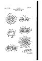
- Fig. 1 is a plan view of a socket member adapted for use in the socket assembly of the invention
- Fig. 2 is a view in section taken on line 2-2 of Fig. 1;
- Fig. 3 is a perspective view of a pronged attaching member for use in the socket assembly
- Fig. 4 is a view in elevation, partly in section, of the component parts of the socket assembly during attachment to a supporting sheet;
- Fig. 5 is a view in elevation, partly in section, of the component parts of the socket assembled on a supporting sheet and a stud member snapped into engagement therewith;
- Fig. 6 is a view in section taken on line 6-6 of Fig. 5, showing the arrangement of the attaching prongs in relation to the socket member.
- a snap fastener socket assembly [0, comprising a socket member I2 and an attaching member 14 which are adapted to be assembled on opposite sides of a supporting'sheet
- the socket member is substantially square, and' comprises abas 20,.a stud-receiving portion 22 disposed. centrally in the base, and an upwardly and: inwardly turned portion 24 about the periphery forming arecess 26.
- the corners 21 of the square base maybe rounded as illustrated to improve-theappearance of the fastener and to facilitate attachment as will be hereinafter described.
- Thestud-receiving portion 22 may be conveniently formed by providing an upwardly extending cylindricalportion 28-having a pair of'horizontal'slots 30 disposed on opposite sides'thereof.
- a spring member 32 is assembled on the base, and comprises a retaining portion 34 disposed in therecess- 26, and a pair of looped portions 36' extending inwardly there.- from on opposite sides ofthe stud-receiving portion.
- the looped portions 36 each have a studengaging leg- 38 disposed'in a slot 30 to engage and retain the stud l8.-
- the looped portions 36' are so arrangedinthe socket member as to extend across a line extending between diagonally-opposed corners of the base, so that the looped portion of'the spring isspaced-apart from the adjacent corner for a purpose to be hereinafter described.
- the attaching member [4 comprises an attaching base 40, which may be substantially square with a square opening therein as illustrated in Fig. 3, and is provided with attaching prongs 42 extending downwardly from each corner of the attaching base.
- the attaching base may have any desired shape for hand attachment, provided the attaching prongs are so disposed thereon as to enable them to engage the socket member at the corners of the socket base, as will be hereinafter described.
- the parts are aligned on opposite sides of the sheet and forced together so that the prongs 42 pierce the sheet and engage the base at the corners thereof. (See Fig. 4.)
- the prongs 42 turn outwardly on the base and. pass under the retaining portion 34 of the spring and into the recess 26 at the rounded corners 21.
- the base 20 may be provided with an embossed portion 44, forming an inclined camming surface 46 for engagement by the prong ends when the parts are forced together.
- the ends of the prongs 42 may be pre-bent outwardly prior to assembly to assist in curling the prongs in the proper direction.
- the arrangement of the spring in the socket and the prongs on the attaching member allows the prongs to engage the base without interfering with the action of the looped portion of the spring, since the prongs must always engage the base at the corners of the socket member.
- the attaching member is square, it may be applied to the socket in any one of four directions, which makes the socket assembly of the invention particularly adapted for assembly by automatic attaching machines. In such machines the component parts of the socket slide down suitably shaped troughs to the attaching mechanism.
- a snap fastener socket member adapted for attachment to a supporting sheet by a pronged attaching cap, said socket member comprising a substantially square base having a stud-receiving portion disposed centrally therein, an upstanding peripheral wall provided with an inwardly curled free end portion providing a recess around the periphery of the base, an intermediate prongcurling portion providing camming surfaces extending inwardly and upwardly from the peripheral wall, and a spring member assembled on the base above said camming surfaces, said spring member comprising a retaining portion disposed in said recess and spaced from said base and a pair of looped portions having substantially parallel stud-engaging legs disposed on opposite sides of the stud-receiving portion, said looped portions being spaced from said spring-retaining portion and said inwardly curled portion of said peripheral wall at the corners of the base, said prong-curling portion forming a curling die to curl the prongs of an attaching cap outwardly into said recess under the spring-
- a snap fastener socket member adapted for attachment to a supporting sheet by a pronged attaching cap, said socket member comprising a polygonal base having a stud-receiving portion disposed centrally thereon, an upstanding peripheral wall provided with an inwardly curled free end portion providing a recess around the periphery of the base, an intermediate prongcurling portion providing camming surfaces extending inwardly and upwardly from the peripheral wall, and a spring member assembled on the base above said camming surfaces, said spring member comprising a retaining portion disposed in said recess and spaced from the base and a pair of looped portions having substantially parallel stud-engaging legs disposed on opposite sides of the stud-receiving portion, said looped portions being spaced from said spring-retaining portion and said inwardly curled portion of said peripheral wall at opposing corners of said polygonal base, said prong-curling portion forming a curling die to curl the prongs of an attaching cap outwardly into said reces
Description
Jan. 27, 1953 J. BLAZEJ SNAP FASTENER SOCKET ASSEMBLY Filed Aug. 29, 1949 \NV'ENTOR'.
JOq/EZ/BLAZEJ, BY ZZ/ l4 ATTORNEY.
Patented Jan. 27, 1953 UNITED STATES PATENT OFFICE Joseph. Bdazej, Chicago, Ill.,, assignor to United-- Carr; Fastener Corporation, Cambridge, Mass... a corporation of Massachusetts- Application August 29, 1949, SerialN'o; 112,920?
2 Claims. 1.
This invention relates, to snap. fasteners, and has particular reference to asnapfastener socket assembly adapted'to be readilyattached to asupporting sheet of cloth or the like and to an: attaching cap for use insuch assembly;
The object of the invention: is. to. provide a snap fastener socket assembly in. which a. socket member having a multi-looped: stud-engaging spring and an attaching member havingxattaching prongs are shaped and arranged tobe assembled on opposite sides of a supporting sheet so that the prongs pierce the sheetand engage the socket member without interfering with. the action of the spring.
A further object of the invention isto provide a snap fastener socket assembly in which a socket member having a multi-looped spring is provided with outwardly extending corners for receiving prongs of an attachingmembenwithout interfering with the action of the spring.
A still further: object of the invention is to provide a snap fastener socket assembly comprising asubstantially square socket member having a spring with stud-engaging arms disposedv diagonally across opposite corners of' the socket memher and an attaching member having prongs adapted to engage the socket; inv the corners of the square.
Other objects of the invention will, in part, be obvious, and will, in part, appear hereinafter. For a fuller understanding of the nature and objects of the invention, reference should be had to the following detailed description, taken in conjunction with the accompanying drawing, in which:
Fig. 1 is a plan view of a socket member adapted for use in the socket assembly of the invention;
Fig. 2 is a view in section taken on line 2-2 of Fig. 1;
Fig. 3 is a perspective view of a pronged attaching member for use in the socket assembly;
Fig. 4 is a view in elevation, partly in section, of the component parts of the socket assembly during attachment to a supporting sheet;
Fig. 5 is a view in elevation, partly in section, of the component parts of the socket assembled on a supporting sheet and a stud member snapped into engagement therewith; and
Fig. 6 is a view in section taken on line 6-6 of Fig. 5, showing the arrangement of the attaching prongs in relation to the socket member.
Referring to the drawing, there is illustrated a snap fastener socket assembly [0, comprising a socket member I2 and an attaching member 14 which are adapted to be assembled on opposite sides of a supporting'sheet |'6, for snapping, engagement with a Stud 18 In the preferred form, the socket member; is substantially square, and' comprises abas 20,.a stud-receiving portion 22 disposed. centrally in the base, and an upwardly and: inwardly turned portion 24 about the periphery forming arecess 26. The corners 21 of the square base maybe rounded as illustrated to improve-theappearance of the fastener and to facilitate attachment as will be hereinafter described. Thestud-receiving portion 22 may be conveniently formed by providing an upwardly extending cylindricalportion 28-having a pair of'horizontal'slots 30 disposed on opposite sides'thereof. A spring member 32 is assembled on the base, and comprises a retaining portion 34 disposed in therecess- 26, and a pair of looped portions 36' extending inwardly there.- from on opposite sides ofthe stud-receiving portion. The looped portions 36 each have a studengaging leg- 38 disposed'in a slot 30 to engage and retain the stud l8.- The looped portions 36' are so arrangedinthe socket member as to extend across a line extending between diagonally-opposed corners of the base, so that the looped portion of'the spring isspaced-apart from the adjacent corner for a purpose to be hereinafter described.
The attaching member [4 comprises an attaching base 40, which may be substantially square with a square opening therein as illustrated in Fig. 3, and is provided with attaching prongs 42 extending downwardly from each corner of the attaching base. Although the square attaching member is preferred for attachment by automatic machines, the attaching base may have any desired shape for hand attachment, provided the attaching prongs are so disposed thereon as to enable them to engage the socket member at the corners of the socket base, as will be hereinafter described.
To assemble the component parts of the socket assembly on the supporting sheet, the parts are aligned on opposite sides of the sheet and forced together so that the prongs 42 pierce the sheet and engage the base at the corners thereof. (See Fig. 4.) As the parts are forced further together, the prongs 42 turn outwardly on the base and. pass under the retaining portion 34 of the spring and into the recess 26 at the rounded corners 21. To insure that the prongs 42 curl outwardly, the base 20 may be provided with an embossed portion 44, forming an inclined camming surface 46 for engagement by the prong ends when the parts are forced together. In some cases the ends of the prongs 42 may be pre-bent outwardly prior to assembly to assist in curling the prongs in the proper direction.
The arrangement of the spring in the socket and the prongs on the attaching member allows the prongs to engage the base without interfering with the action of the looped portion of the spring, since the prongs must always engage the base at the corners of the socket member. Since the attaching member is square, it may be applied to the socket in any one of four directions, which makes the socket assembly of the invention particularly adapted for assembly by automatic attaching machines. In such machines the component parts of the socket slide down suitably shaped troughs to the attaching mechanism. During the attaching operation with the socket assembly of the invention, it is only necessary that the square socket and the square attaching member be aligned in the attaching mechanism so that the corners of the squares are opposite one another, and consequently both the socket and the attaching cap may enter the trough in any one of four directions, and no special positioning or alignment mechanism is necessary in the machine.
Since certain obvious changes may be made in the device without departing from the scope of the invention, it is intended that all matter contained herein be interpreted in an illustrative and not in a limiting sense.
I claim:
1. A snap fastener socket member adapted for attachment to a supporting sheet by a pronged attaching cap, said socket member comprising a substantially square base having a stud-receiving portion disposed centrally therein, an upstanding peripheral wall provided with an inwardly curled free end portion providing a recess around the periphery of the base, an intermediate prongcurling portion providing camming surfaces extending inwardly and upwardly from the peripheral wall, and a spring member assembled on the base above said camming surfaces, said spring member comprising a retaining portion disposed in said recess and spaced from said base and a pair of looped portions having substantially parallel stud-engaging legs disposed on opposite sides of the stud-receiving portion, said looped portions being spaced from said spring-retaining portion and said inwardly curled portion of said peripheral wall at the corners of the base, said prong-curling portion forming a curling die to curl the prongs of an attaching cap outwardly into said recess under the spring-retaining portion when the socket member and cap are assembled on the supporting sheet.
2. A snap fastener socket member adapted for attachment to a supporting sheet by a pronged attaching cap, said socket member comprising a polygonal base having a stud-receiving portion disposed centrally thereon, an upstanding peripheral wall provided with an inwardly curled free end portion providing a recess around the periphery of the base, an intermediate prongcurling portion providing camming surfaces extending inwardly and upwardly from the peripheral wall, and a spring member assembled on the base above said camming surfaces, said spring member comprising a retaining portion disposed in said recess and spaced from the base and a pair of looped portions having substantially parallel stud-engaging legs disposed on opposite sides of the stud-receiving portion, said looped portions being spaced from said spring-retaining portion and said inwardly curled portion of said peripheral wall at opposing corners of said polygonal base, said prong-curling portion forming a curling die to curl the prongs of an attaching cap outwardly into said recess under the spring-retaining portion when the socket member and cap are assembled on the supporting sheet.
JOSEPH BLAZEJ.
REFERENCES CITED The following references are of record in the file of this patent:
UNITED STATES PATENTS Number Name Date 1,222,096 Galt Apr. 10, 1917 1,656,040 Carr Jan. 10, 1928 2,015,049 Carr Sept. 1'7, 1935 2,286,438 Reiter June 16, 1942 2,509,434 Huelster May 30, 1950
Priority Applications (1)
| Application Number | Priority Date | Filing Date | Title |
|---|---|---|---|
| US112920A US2626442A (en) | 1949-08-29 | 1949-08-29 | Snap fastener socket assembly |
Applications Claiming Priority (1)
| Application Number | Priority Date | Filing Date | Title |
|---|---|---|---|
| US112920A US2626442A (en) | 1949-08-29 | 1949-08-29 | Snap fastener socket assembly |
Publications (1)
| Publication Number | Publication Date |
|---|---|
| US2626442A true US2626442A (en) | 1953-01-27 |
Family
ID=22346548
Family Applications (1)
| Application Number | Title | Priority Date | Filing Date |
|---|---|---|---|
| US112920A Expired - Lifetime US2626442A (en) | 1949-08-29 | 1949-08-29 | Snap fastener socket assembly |
Country Status (1)
| Country | Link |
|---|---|
| US (1) | US2626442A (en) |
Cited By (4)
| Publication number | Priority date | Publication date | Assignee | Title |
|---|---|---|---|---|
| US3358339A (en) * | 1965-10-04 | 1967-12-19 | Mary A Strehlein | Side entrance fastener which on closing gives an audible click and locks |
| DE1262059B (en) * | 1965-02-17 | 1968-02-29 | Prym Werke William | Snap fastener part |
| US20100071175A1 (en) * | 2007-03-08 | 2010-03-25 | Ykk Corporation | Snap fastener part |
| US11388960B2 (en) * | 2019-09-16 | 2022-07-19 | Riri S.A. | Snap button, and a female component for such snap button |
Citations (5)
| Publication number | Priority date | Publication date | Assignee | Title |
|---|---|---|---|---|
| US1222096A (en) * | 1915-07-08 | 1917-04-10 | De Long Hook & Eye Co | Snap-fastener. |
| US1656040A (en) * | 1928-01-10 | Fastener | ||
| US2015049A (en) * | 1933-01-12 | 1935-09-17 | United Carr Fastener Corp | Separable snap fastener socket and installation thereof |
| US2286438A (en) * | 1941-09-10 | 1942-06-16 | Daniel I Reiter | Garment fastener |
| US2509434A (en) * | 1946-06-06 | 1950-05-30 | Scovill Manufacturing Co | Prong ring snap fastener attachment |
-
1949
- 1949-08-29 US US112920A patent/US2626442A/en not_active Expired - Lifetime
Patent Citations (5)
| Publication number | Priority date | Publication date | Assignee | Title |
|---|---|---|---|---|
| US1656040A (en) * | 1928-01-10 | Fastener | ||
| US1222096A (en) * | 1915-07-08 | 1917-04-10 | De Long Hook & Eye Co | Snap-fastener. |
| US2015049A (en) * | 1933-01-12 | 1935-09-17 | United Carr Fastener Corp | Separable snap fastener socket and installation thereof |
| US2286438A (en) * | 1941-09-10 | 1942-06-16 | Daniel I Reiter | Garment fastener |
| US2509434A (en) * | 1946-06-06 | 1950-05-30 | Scovill Manufacturing Co | Prong ring snap fastener attachment |
Cited By (5)
| Publication number | Priority date | Publication date | Assignee | Title |
|---|---|---|---|---|
| DE1262059B (en) * | 1965-02-17 | 1968-02-29 | Prym Werke William | Snap fastener part |
| US3358339A (en) * | 1965-10-04 | 1967-12-19 | Mary A Strehlein | Side entrance fastener which on closing gives an audible click and locks |
| US20100071175A1 (en) * | 2007-03-08 | 2010-03-25 | Ykk Corporation | Snap fastener part |
| US8042238B2 (en) * | 2007-03-08 | 2011-10-25 | Ykk Corporation | Snap fastener part |
| US11388960B2 (en) * | 2019-09-16 | 2022-07-19 | Riri S.A. | Snap button, and a female component for such snap button |
Similar Documents
| Publication | Publication Date | Title |
|---|---|---|
| USRE22543E (en) | Fastening device | |
| US2225592A (en) | Fastener attached structure and fastener for the same | |
| US2648091A (en) | Fastener assembly | |
| US2223622A (en) | Trim fastener | |
| US2626442A (en) | Snap fastener socket assembly | |
| JP5940112B2 (en) | Decorative object holder | |
| US2178113A (en) | Holder for towels and other articles | |
| US2283125A (en) | Locking snap fastener | |
| US2629157A (en) | Fastener | |
| US2197590A (en) | Fastener | |
| US2677853A (en) | Adjustable and separable hinge | |
| GB770606A (en) | Improved clip | |
| US2626443A (en) | Snap fastener socket assembly | |
| US2767454A (en) | Snap fastener socket | |
| US2626441A (en) | Snap fastener socket assembly | |
| US2898656A (en) | Fastening device | |
| US2191412A (en) | Snap fastener stud | |
| US2109402A (en) | Carpet fastener | |
| US2173198A (en) | Self-piercing fastener member | |
| US1434245A (en) | Fastener | |
| US2672748A (en) | Key holder frame | |
| US2961728A (en) | Hook and eye garment fastener | |
| US2698473A (en) | Two-piece wire spring socket | |
| US3417442A (en) | Quick release fasteners | |
| US1753696A (en) | Slide fastener with attached resilient socket |