US2624426A - Automatic adjusting device - Google Patents
Automatic adjusting device Download PDFInfo
- Publication number
- US2624426A US2624426A US736484A US73648447A US2624426A US 2624426 A US2624426 A US 2624426A US 736484 A US736484 A US 736484A US 73648447 A US73648447 A US 73648447A US 2624426 A US2624426 A US 2624426A
- Authority
- US
- United States
- Prior art keywords
- shoe
- brake
- pawls
- plunger member
- ratchet
- Prior art date
- Legal status (The legal status is an assumption and is not a legal conclusion. Google has not performed a legal analysis and makes no representation as to the accuracy of the status listed.)
- Expired - Lifetime
Links
Images


Classifications
-
- F—MECHANICAL ENGINEERING; LIGHTING; HEATING; WEAPONS; BLASTING
- F16—ENGINEERING ELEMENTS AND UNITS; GENERAL MEASURES FOR PRODUCING AND MAINTAINING EFFECTIVE FUNCTIONING OF MACHINES OR INSTALLATIONS; THERMAL INSULATION IN GENERAL
- F16D—COUPLINGS FOR TRANSMITTING ROTATION; CLUTCHES; BRAKES
- F16D65/00—Parts or details
- F16D65/38—Slack adjusters
- F16D65/40—Slack adjusters mechanical
- F16D65/52—Slack adjusters mechanical self-acting in one direction for adjusting excessive play
- F16D65/54—Slack adjusters mechanical self-acting in one direction for adjusting excessive play by means of direct linear adjustment
- F16D65/546—Slack adjusters mechanical self-acting in one direction for adjusting excessive play by means of direct linear adjustment for mounting within the confines of a drum brake
Definitions
- Figure 1 is a side elevationof a brakeassembly which incorporates one form ofmy improvedautomatic adjusting device
- the illustrated brake includes the usual primary and-secondary" shoes Hand 14', which are anchored at their lower ends against a'member l6 rigidlysecured to the backing plate 18; and which are adapted to be spread at theirupper'ends by means of a hydraulic wheel cylinder 20 carried by the back ing plate.
- Return springs 22 and are provided for urging the shoes to released position, "and hold-down devices '26 and'ZBmay berused'to retainthe shoes in the proper position laterally.
- the improved automatic adjusting device is a unit which is adaptedto be'secured 1:20. -:.to the-'brake shoe,:and which :consistsof .two primary elementsa housingmember38l and. a --plungermember 40.5
- the center'portion lfi of the housing--38 is through openings provided in the rim'30 and the Each of the brake shoes l2 and"! has the usual "of the'lining, 'sothat it 'engagesthebrakedrum 3% whenever the face of the lining engages the brake drum.
- the inner end 56 of plunger member 26 extends inwardly beyond the edge of the shoe web and is arranged to engage a stop member 52, which is carried by the supporting member, or backing plate, 18.
- the stop member 52 is preferably formed as an eccentric adjusting member which can be manually operated to provide an initial, or factory, adjustment for the brake shoe.
- a similar eccentric .adjustor 54 is located at the opposite side of the brake and engages secondary shoe I4. 1
- the opposite sides of the opening 41 in housing 38 are provided with ratchet-toothed surfaces 56 and 58.
- the plunger member 40 has a plural-'- ity (preferably 3) of laterally-extending slots 60.
- each of the laterally-extending slots Located in each of the laterally-extending slots.
- pawls 62 and 64 are two pawls 62 and 64, the pawls 62 of the several slots engaging the ratchet-toothed'sur face 56, and the pawls 64 of the several slots engaging the ratchet-toothed surface 58.
- the pawls of each pair are urged into engagement with the opposed ratchet-toothed surfaces by means of a light compression spring 66 mounted between the opposed pawls.
- the ends of the slots (illv are reduced in size by forming a nib 68 at each end of each slot after the springs and pawls have been assembled.
- the arrangement of the pawls 62 and 64, and of the ratchet-toothed surfaces 56 and 58, is such that relative movement of the shoe [2 and plunger member 4%!) can occur in one direction only.
- the shoe can move radially outwardly with respect to the plunger member, but it is prevented from moving radially inwardly with respect to the plunger member.
- plunger member 40 due to its engagement with the brake drum, will be forced inwardlywith respect to the shoe. Or, more correctly, during application of the brake, the plunger will remain stationary, while the shoe, as the lining wears, will move outwardly with respect to. the plunger. As successive teeth on ratchet-toothed surfaces 56 and 58 are engaged by the pawls 62 and 64, the plunger member 40 will be retained in its adjusted position with respect to the shoe. In other words, the shoe will gradually move radially outwardly with respect to the plunger.
- the plunger member 46 will prevent the shoe from returning as far inwardly as its previous released position.
- the released position clearance between the outer face of the brake lining and the inner face of the brake drum will remain substantially constant and will be equal to the distance during brake application between the inner end 58 of the plunger member and the engaging surface of stop member 52.
- the increment of adjustment i. e. the length of relative movement between the plunger member and shoe before the next pawl clears the next tooth, may be as small as the pitch of a single tooth divided by the total number of pawls. In this case, since six pawls are shown, if we assume that the pitch of a single tooth is .042 inch, then the increment of adjustment can be as low as .007 inch because there are six pawls. In order to obtain the smallest possible increment of adjustment, two things arenecessary.
- the ratchet-toothed surface 56 must be ra- 4 dially offset with respect to the ratchet-toothed surface 58 by an amount which is equal to, or a multiple of, the increment of adjustment.
- any corresponding points on successive pawls should be spaced apart a distance which differs from a multiple of the pitch of a single tooth by an amount equal to, or a multiple of, the increment of adjustment.
- the illustrated form of the device obtains the maximum number of adjustments, i. e. has a ,minimum increment of adjustment, because the center pawl, the lower center pawl, the upper left hand pawl, and the lower left hand pawl will clear their respective engaging teeth in the order listed, thus completing a cycle of operation of the automatic adjustment, and providinga total adjustment equivalent to the pitch of one ratchet tooth. This operation will, of course, continue until the lining is ready to be replaced.
- Figures 5 to '7 operates on the same principle as that illustrated in Figures 1 to 4.
- the six pawls 62a and 64a are carried in slots 60a provided in the housing member 38a, and the ratchet-toothed surfaces 56a and 58a are provided on opposite sides of plunger member 40a.
- a closure plate 70 is secured to the underside of the housing member bymeans of a plurality of swaged nibs (2 (see Figure 7).
- the plate 10 retains both the plunger 40a and the pawls 62a and 64a in assembled position inside the housing member.
- Each of the pawls 62a and 64a is recessed, as shown at 14, to receive a light compression 66a, which urges the respective pawl into engagement with one of the ratchet-toothed surfaces provided on the plunger member.
- a light compression 66a which urges the respective pawl into engagement with one of the ratchet-toothed surfaces provided on the plunger member.
- the ends of the slots 60a are reduced in size by projections 681]. formed as integral parts of the housing member.
- the pawls and springs are assembled by inserting them in their slots through the bottom of the housing member before the closure plate 10 is v placed in position.
- an automatic adjusting device for maintaining a substantially constant clearance between drum and lining in released position comprising a unitary housing member secured to the shoe and having a radially extending opening therethrough, said housing member having six separately located laterally extending slots therein, three of which are located at each side of the radially extending opening, a plunger member extending through said opening and through the shoe and shoe lin- I ing to bring its outer end substantially flush with the face of the lining, the other end of the plunger member being arranged to engage the supporting member and thereby determine the released position of the shoe, said plunger member having ratchet-toothed surfaces formed on opposite sides thereof, the teeth of one surface being slightly
- a brake having a rotatable brake drum, a non-rotatable supporting member, and a brake shoe carried by the supporting member and adapted to at times frictionally engage the drum, said brake shoe having a friction material lining which is adjacent the drum and which is gradually worn down as a result of successive tomaticadjustingl devicezfor maintaining a e-subtantiallwconstant clearance between-rdrumnand -lil'lillg in released position: comprising: a single piece housing -member securedi-tothe shoeand having a sra'dially 2 extending opening therethrough; said housing member having.
- an automatic adjusting device comprising a, housing member secured to the shoe and having a radially extending opening therethrough, a plunger member extending through said opening and through the shoe with its outer end substantially flush with the face of the shoe, the other end of the plunger member being arranged to engage a stop member and thereby determine the released position of the shoe, one of said members having a plurality of laterally extending slots therein, the other of said members having two oppositely-facing ratchet-toothed surfaces, a plurality of U shaped pawl members arranged in oppositely-facing pairs, each of said pawl members being individually carried in one of the aforementioned slots, said pawl members being arranged to cooperate with the ratchettoothed surfaces to permit the shoe to move radially outwardly with respect to the plunger member but prevent the shoe from moving radially inwardly with respect to the plunger member, the teeth of one of said ratchet-toothed surfaces being offset radially with respect to the teeth of the other
Landscapes
- Engineering & Computer Science (AREA)
- General Engineering & Computer Science (AREA)
- Mechanical Engineering (AREA)
- Braking Arrangements (AREA)
Description
1953 R. A. GOEPFRICH 2,624,426
- AUTOMATIC ADJUSTING DEVICE Filed March 22, 1947 3 Sheets-Sheet l J 1953 R. A. GOEPFRICH 2,624,426
' AUTOMATIC ADJUSTING DEVICE 3 Sheets-Sheet 2 Filed March 22, 1947 A TTOB/VEY Jan. 6, 1953 R. A. GOEPFRICH AUTOMATIC ADJUSTING DEVICE 3 Sheets-Sheet 3 Filed March 22, 1947 1* INVENTOR.
W W i. w i m w Patented Jan. 6,' 1953 UNITED STATES Z PATiENT OF FKIE 2,624,426 AUTOMATICTADJUSTING DEVICE LXRudoIph A; Goepfrich, South Bend, Ind:,-assignor u-i-to Bendix Aviation Corporation; South Bend,
Ind.-, a corporation of Delaware ApplicationMarch 22, 1947;"S'e11ial' N 0.7365484 3; Claims. (Cl.-,;'188-=1-+Z9;5)
i This invention relates =toan improved automatic adjusting device, which is to be usedincon-junction with a brake shoe for the purpose'ofmaintaining a substantially constant released position clearance betweensaid'shoe and thecooperating -brake shoesinto engagement with'the rotatable brake drum.
'In Patent No, 2,168,646,which-issued August 8, 1939, I disclosed and claimed.- an' automatic adjusting device in which a plurality ct -springand havingits' outer endflush with "theouter face of v the brake shoe lining.
=rim 30, strengthening web:.32,'and lining 34 car- -ried by. the'rimand composed of suitable friction lining material.
successivelstops aremade by bringing the brake drum 36, the linings 34 are gradually worn --'down,='- reducing their. thickness, and increasing thereleased positionclearance between the outer face: of the lining and x the drum, unless. suitable vJ means are provided. for preventing an excessive increase in said clearance. Normally .theishoes a require manual adjustment to compensate for wear, but the device. disclosed :herein .causes the adjustment tobe made automatically, without at- The primary object of= the present-invention 'is -tention'-: from the driver of'the vehicle on which to provide an automatic adjusting'device 'similar to the one disclosed in Patent-No; 2,l68,'646,=but
easier to assemble and retain assembled, simpler in construction, easier to contain in a-given space, and more positive in operationthan the device of the patent.
Otherobjects and advantages of th present invention will become apparent durin'g'th'e following discussion, reference being" had therein''- to the accompanying drawings, in which:
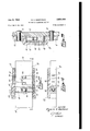
Figure 1 is a side elevationof a brakeassembly which incorporates one form ofmy improvedautomatic adjusting device; 1
Figure 2 is an'enlarged sectionalview-"of'the operating parts ofthe automatic adjusting =d'evice of-Figure l Figures 3 and 4 are cross sectional views'of' the automatic adjusting device, taken 'on the lines 3 -3 and 4- -4, respectively, of Figure 2;
' servo type, although it is applicable to any conventional brake construction. The illustrated brake includes the usual primary and-secondary" shoes Hand 14', which are anchored at their lower ends against a'member l6 rigidlysecured to the backing plate 18; and which are adapted to be spread at theirupper'ends by means of a hydraulic wheel cylinder 20 carried by the back ing plate. Return springs 22 and are provided for urging the shoes to released position, "and hold-down devices '26 and'ZBmay berused'to retainthe shoes in the proper position laterally.
- the brake is used.
Referring' first ,to the embodiment shown in -.Figures 1- to 4-,:the improved automatic adjusting device is a unit which is adaptedto be'secured 1:20. -:.to the-'brake shoe,:and which :consistsof .two primary elementsa housingmember38l and. a --plungermember 40.5 The housing member =38 has a ears-42 :at opposite ends thereof. which are adapt- M edtobe secured by suitable fastening -members v1:25. iallvto th ebs 32 ..;0f'. the respective ,brake Lshoe.
"It. will be noted-that: in? the illustrated, brake, aonly oneautomatic adjustingdevice' is shown, and that device ==iszmountedt :on? 'the primary brake shoe l 12. 1 This has been done because :the relative rates of wear ofthe-two shoes are so disparate as to make automatio adjusting'ofthe secondary shoe-='relatively unimportant. "In other words, the primary-shoe wears so=much fasterthan the --secondary' shoe-that it is likely to. be substan- '-tially-Worn outbythe time thesecondary shoe -requi-res a manual adjustment. I The reason for this lies" in the unequal 'amounts of work performed by the two shoes, due to'the fact that the primary shoe l2 isthe self-energizing shoe'of the -40 brake whenever the brake-is applied with the-vehicle'moving-in a forward direction, the arrow F being used in the drawing to indicate the direction of rotation of-the' drum 33 during forward movement of the vehicle.
The center'portion lfi of the housing--38 is through openings provided in the rim'30 and the Each of the brake shoes l2 and"! has the usual "of the'lining, 'sothat it 'engagesthebrakedrum 3% whenever the face of the lining engages the brake drum. The inner end 56 of plunger member 26 extends inwardly beyond the edge of the shoe web and is arranged to engage a stop member 52, which is carried by the supporting member, or backing plate, 18. The stop member 52 is preferably formed as an eccentric adjusting member which can be manually operated to provide an initial, or factory, adjustment for the brake shoe. A similar eccentric .adjustor 54 is located at the opposite side of the brake and engages secondary shoe I4. 1
The opposite sides of the opening 41 in housing 38 are provided with ratchet- toothed surfaces 56 and 58. The plunger member 40 has a plural-'- ity (preferably 3) of laterally-extending slots 60.
Located in each of the laterally-extending slots.
63? are two pawls 62 and 64, the pawls 62 of the several slots engaging the ratchet-toothed'sur face 56, and the pawls 64 of the several slots engaging the ratchet-toothed surface 58. The pawls of each pair are urged into engagement with the opposed ratchet-toothed surfaces by means of a light compression spring 66 mounted between the opposed pawls. In order to retain the pawls in assembled position in plunger member M3, in case the latter should be disengaged from housing member 38, the ends of the slots (illv are reduced in size by forming a nib 68 at each end of each slot after the springs and pawls have been assembled.
The arrangement of the pawls 62 and 64, and of the ratchet- toothed surfaces 56 and 58, is such that relative movement of the shoe [2 and plunger member 4%!) can occur in one direction only. Thus, the shoe can move radially outwardly with respect to the plunger member, but it is prevented from moving radially inwardly with respect to the plunger member.
In operation, as the lining 34 wears away,
The increment of adjustment, i. e. the length of relative movement between the plunger member and shoe before the next pawl clears the next tooth, may be as small as the pitch of a single tooth divided by the total number of pawls. In this case, since six pawls are shown, if we assume that the pitch of a single tooth is .042 inch, then the increment of adjustment can be as low as .007 inch because there are six pawls. In order to obtain the smallest possible increment of adjustment, two things arenecessary. First of all, the ratchet-toothed surface 56 must be ra- 4 dially offset with respect to the ratchet-toothed surface 58 by an amount which is equal to, or a multiple of, the increment of adjustment. Furthermore, any corresponding points on successive pawls (such as the tips of the pawls) should be spaced apart a distance which differs from a multiple of the pitch of a single tooth by an amount equal to, or a multiple of, the increment of adjustment.
The illustrated form of the device obtains the maximum number of adjustments, i. e. has a ,minimum increment of adjustment, because the center pawl, the lower center pawl, the upper left hand pawl, and the lower left hand pawl will clear their respective engaging teeth in the order listed, thus completing a cycle of operation of the automatic adjustment, and providinga total adjustment equivalent to the pitch of one ratchet tooth. This operation will, of course, continue until the lining is ready to be replaced.
The preferred form of the invention is shown in, Figures 5 to 7. In applying numerals to these figures, the letter a has been added to the numbers used in Figures 1 to 4 to designate similar elements. Where new elements are indicated, new numeralsare used.
The automatic adjustment of Figures 5 to '7 operates on the same principle as that illustrated in Figures 1 to 4. However, the six pawls 62a and 64a are carried in slots 60a provided in the housing member 38a, and the ratchet-toothed surfaces 56a and 58a are provided on opposite sides of plunger member 40a. In order .to retain plunger member We in assembled relation with housing member 380,, even when said members are removed from the brake shoe, a closure plate 70 is secured to the underside of the housing member bymeans of a plurality of swaged nibs (2 (see Figure 7). The plate 10 retains both the plunger 40a and the pawls 62a and 64a in assembled position inside the housing member.
Each of the pawls 62a and 64a is recessed, as shown at 14, to receive a light compression 66a, which urges the respective pawl into engagement with one of the ratchet-toothed surfaces provided on the plunger member. In order to retain the pawls in their slots 66a when the plunger member is removed from the opening in the housing member, the ends of the slots 60a are reduced in size by projections 681]. formed as integral parts of the housing member. The pawls and springs are assembled by inserting them in their slots through the bottom of the housing member before the closure plate 10 is v placed in position.
' -to, or a'multiple of,-.the.increment10f adjustz'ernent.
:.-Al=though certain particular lembodiments of f, :my invention have beenzdescribed, it willmbe un- *:;iderstoodby those skilled-in-theart that the obectof the invention maybe attainedabylthe use f: constructions different inv :certain c respects from those disclosed without departing from the:
underlying principles of the invention. I therefore desire by the following claims to include within the scope of my invention all such variations and modifications by which substantially the results of my invention may be obtained through the use of substantially the same or equivalent means.
I claim:
1. For use in a, brake having a rotatable brake drum, a non-rotatable supporting member, and a brake shoe carried by the supporting member and adapted to at times frictionally engage the drum, said brake shoe having a friction material lining which is adjacent the drum and which is gradually worn down as a result of successive frictional engagements with the drum; an automatic adjusting device for maintaining a substantially constant clearance between drum and lining in released position comprising a unitary housing member secured to the shoe and having a radially extending opening therethrough, said housing member having six separately located laterally extending slots therein, three of which are located at each side of the radially extending opening, a plunger member extending through said opening and through the shoe and shoe lin- I ing to bring its outer end substantially flush with the face of the lining, the other end of the plunger member being arranged to engage the supporting member and thereby determine the released position of the shoe, said plunger member having ratchet-toothed surfaces formed on opposite sides thereof, the teeth of one surface being slightly offset radially with respect to the teeth of the other surface, six U-shaped pawl members, each of which is carried in one of the slots in the housing member, said pawl members being arranged to cooperate with the ratchet-toothed surfaces of the plunger member to permit the shoe to move radially outwardly with respect to the plunger member but prevent the shoe from moving radially inwardly with respect to the plunger member, corresponding points on the radially spaced pawls being spaced apart a distance which differs slightly from a multiple of the pitch of a single tooth, each of the said six pawls thus being arranged to drop successively into the next teeth on the ratchet-toothed surfaces as the relative movement of shoe and plunger member takes place, and six springs, each located in one of the slots in the housing member and bearing against a recessed portion of said pawl to urge the respective pawl into engagement with one of the ratchet-toothed surfaces of the plunger member, the inner edges of the slots in the housing member being partially closed to positively retain the pawls in assembly.
2. For use in a brake having a rotatable brake drum, a non-rotatable supporting member, and a brake shoe carried by the supporting member and adapted to at times frictionally engage the drum, said brake shoe having a friction material lining which is adjacent the drum and which is gradually worn down as a result of successive tomaticadjustingl devicezfor maintaining a e-subtantiallwconstant clearance between-rdrumnand -lil'lillg in released position: comprising: a single piece housing -member securedi-tothe shoeand having a sra'dially 2 extending opening therethrough; said housing member having. a plurality of-laterally extending individual slots "therein ...-,-:arranged '---in uadially-spaced pairs, the two. slots at each pair being locatedcat opposite sides of 510 the radially extending opening, a plunger member extendingthrough*said'opening and through lthe; shoes-and :shoe lining to bring vits outerfiend substantially flush with theafacepf: the -1ining, the other end of the plunger member being arranged to engage the supporting member and thereby determine the released position of the shoe, said plunger member having ratchettoothed surfaces formed on opposite sides thereof, the teeth of one surface being slightly offset radially with respect to the teeth of the other surface, a plurality of U-shaped pawl members, each of which is carried in one of the slots in the housing member, said pawl members being arranged to cooperate with the ratchet-toothed surfaces of the plunger member to permit the shoe to move radially outwardly with respect to the plunger member but prevent the shoe from moving radially inwardlywith respect to the plunger member, corresponding points on the radially spaced pawls being spaced apart a distance which differs slightly from a multiple of the pitch of a single tooth, the several pawls thus being arranged to drop successively into the next teeth on the ratchet-toothed surfaces as the relative movement of shoe and plunger member takes place, and a plurality of springs, each located in one of the slots in the housing member and bearing against the mid portion of said pawl to urge the respective pawl into engagement with one of the ratchet-toothed surfaces of the plunger member, the inner edges of the slots in the housing member being partially closed to positively retain the pawls in assembly.
3. For use in conjunction with a brake shoe,
an automatic adjusting device comprising a, housing member secured to the shoe and having a radially extending opening therethrough, a plunger member extending through said opening and through the shoe with its outer end substantially flush with the face of the shoe, the other end of the plunger member being arranged to engage a stop member and thereby determine the released position of the shoe, one of said members having a plurality of laterally extending slots therein, the other of said members having two oppositely-facing ratchet-toothed surfaces, a plurality of U shaped pawl members arranged in oppositely-facing pairs, each of said pawl members being individually carried in one of the aforementioned slots, said pawl members being arranged to cooperate with the ratchettoothed surfaces to permit the shoe to move radially outwardly with respect to the plunger member but prevent the shoe from moving radially inwardly with respect to the plunger member, the teeth of one of said ratchet-toothed surfaces being offset radially with respect to the teeth of the other ratchet-toothed surface by an amount equal to a fraction of the pitch of a single 7 tooth, said fraction having a denominator equal to the total number of pawl members, corresponding points on the radially spaced pawls being spaced apart a distance which differs from a multiple of the pitch of a single tooth by a fracfrictional engagements with the drum; an aution of said pitch, said fraction having a denomment of shoe and plunger member takes place,
and a plurality of springs acting on a. recessed portion of the pawl members to urge them into engagement with the ratchet-toothed surfaces.
RUDOLPH A. GOEPFRICH.
REFERENCES CITED The following references are of record in the file of this patent:
UNITED STATES PATENTS Number Name Date Christensen Nov. 20, 1906 Conte Sept. 2, 1913 Ballard May 8, 1917 Goepfrich Aug. 8, 1939 Rasmussen et a1. Oct. 10, 1939 Temple May 28, 1940 Ryan Nov. 26, 1940
Priority Applications (1)
| Application Number | Priority Date | Filing Date | Title |
|---|---|---|---|
| US736484A US2624426A (en) | 1947-03-22 | 1947-03-22 | Automatic adjusting device |
Applications Claiming Priority (1)
| Application Number | Priority Date | Filing Date | Title |
|---|---|---|---|
| US736484A US2624426A (en) | 1947-03-22 | 1947-03-22 | Automatic adjusting device |
Publications (1)
| Publication Number | Publication Date |
|---|---|
| US2624426A true US2624426A (en) | 1953-01-06 |
Family
ID=24960056
Family Applications (1)
| Application Number | Title | Priority Date | Filing Date |
|---|---|---|---|
| US736484A Expired - Lifetime US2624426A (en) | 1947-03-22 | 1947-03-22 | Automatic adjusting device |
Country Status (1)
| Country | Link |
|---|---|
| US (1) | US2624426A (en) |
Citations (7)
| Publication number | Priority date | Publication date | Assignee | Title |
|---|---|---|---|---|
| US836303A (en) * | 1906-04-26 | 1906-11-20 | Carl V J Christensen | Automatic-locking collar. |
| US1072313A (en) * | 1912-08-19 | 1913-09-02 | Pasquale C Conte | Ratchet mechanism. |
| US1224997A (en) * | 1916-06-30 | 1917-05-08 | Wildman Mfg Co | Clutch. |
| US2168646A (en) * | 1937-10-08 | 1939-08-08 | Bendix Prod Corp | Brake |
| US2175446A (en) * | 1936-05-28 | 1939-10-10 | Gen Motors Corp | Slack adjuster |
| US2202125A (en) * | 1938-11-19 | 1940-05-28 | Jr Robert Temple | Pipe press |
| US2222858A (en) * | 1938-01-26 | 1940-11-26 | Ralph J Burton | Brake |
-
1947
- 1947-03-22 US US736484A patent/US2624426A/en not_active Expired - Lifetime
Patent Citations (7)
| Publication number | Priority date | Publication date | Assignee | Title |
|---|---|---|---|---|
| US836303A (en) * | 1906-04-26 | 1906-11-20 | Carl V J Christensen | Automatic-locking collar. |
| US1072313A (en) * | 1912-08-19 | 1913-09-02 | Pasquale C Conte | Ratchet mechanism. |
| US1224997A (en) * | 1916-06-30 | 1917-05-08 | Wildman Mfg Co | Clutch. |
| US2175446A (en) * | 1936-05-28 | 1939-10-10 | Gen Motors Corp | Slack adjuster |
| US2168646A (en) * | 1937-10-08 | 1939-08-08 | Bendix Prod Corp | Brake |
| US2222858A (en) * | 1938-01-26 | 1940-11-26 | Ralph J Burton | Brake |
| US2202125A (en) * | 1938-11-19 | 1940-05-28 | Jr Robert Temple | Pipe press |
Similar Documents
| Publication | Publication Date | Title |
|---|---|---|
| US2669327A (en) | Automatic clearance adjusting mechanism for single-disk, spot-type brakes | |
| US4364455A (en) | Retraction spring for disc brake pads | |
| US2002139A (en) | Automatic brake adjusting and indicating mechanism | |
| US3610373A (en) | Adjuster mechanism for disc brakes | |
| GB1061058A (en) | Improved disc brake | |
| US2762463A (en) | Automatic wear adjustment for brakes | |
| US2624426A (en) | Automatic adjusting device | |
| US3460653A (en) | Brake adjuster | |
| US2168646A (en) | Brake | |
| US3213970A (en) | Automatic adjustor | |
| US2152041A (en) | Brake | |
| GB941352A (en) | Internal shoe drum brake | |
| US2051920A (en) | Brake adjusting device | |
| US3556263A (en) | Automatic brake shoe positioner mechanism | |
| US2296026A (en) | Brake mechanism | |
| US3869026A (en) | Shoe drum brakes | |
| US1913932A (en) | Vehicle brake | |
| US1756983A (en) | Brake | |
| GB1132702A (en) | Improvements in and relating to vehicle drum brakes | |
| US2134564A (en) | Brake | |
| US2472697A (en) | Automatically adjustable disk brake | |
| US2856037A (en) | Automatic brake adjustment device | |
| US2596380A (en) | Brake wear take-up | |
| US3195690A (en) | Adjusting strut and brake shoe connection | |
| US4101010A (en) | Drum brake with automatic adjustment |