US2623948A - Multiplex telegraph receiver employing an electronic distributor - Google Patents
Multiplex telegraph receiver employing an electronic distributor Download PDFInfo
- Publication number
- US2623948A US2623948A US65438A US6543848A US2623948A US 2623948 A US2623948 A US 2623948A US 65438 A US65438 A US 65438A US 6543848 A US6543848 A US 6543848A US 2623948 A US2623948 A US 2623948A
- Authority
- US
- United States
- Prior art keywords
- tube
- conductor
- over
- tubes
- resistor
- Prior art date
- Legal status (The legal status is an assumption and is not a legal conclusion. Google has not performed a legal analysis and makes no representation as to the accuracy of the status listed.)
- Expired - Lifetime
Links
- 239000004020 conductor Substances 0.000 description 250
- 238000010304 firing Methods 0.000 description 27
- 230000011664 signaling Effects 0.000 description 25
- 238000004804 winding Methods 0.000 description 11
- 230000001143 conditioned effect Effects 0.000 description 10
- 230000003750 conditioning effect Effects 0.000 description 8
- 230000007935 neutral effect Effects 0.000 description 8
- 230000010363 phase shift Effects 0.000 description 8
- 230000007246 mechanism Effects 0.000 description 7
- 230000008878 coupling Effects 0.000 description 3
- 238000010168 coupling process Methods 0.000 description 3
- 238000005859 coupling reaction Methods 0.000 description 3
- 230000004075 alteration Effects 0.000 description 2
- 230000005540 biological transmission Effects 0.000 description 2
- 230000000903 blocking effect Effects 0.000 description 2
- 239000013078 crystal Substances 0.000 description 2
- 230000000994 depressogenic effect Effects 0.000 description 2
- 230000009467 reduction Effects 0.000 description 2
- WVQBLGZPHOPPFO-UHFFFAOYSA-N 2-chloro-N-(2-ethyl-6-methylphenyl)-N-(1-methoxypropan-2-yl)acetamide Chemical compound CCC1=CC=CC(C)=C1N(C(C)COC)C(=O)CCl WVQBLGZPHOPPFO-UHFFFAOYSA-N 0.000 description 1
- 241000272470 Circus Species 0.000 description 1
- 241001061260 Emmelichthys struhsakeri Species 0.000 description 1
- 241000699666 Mus <mouse, genus> Species 0.000 description 1
- 101100042880 Mus musculus Snai3 gene Proteins 0.000 description 1
- 230000009471 action Effects 0.000 description 1
- 230000003321 amplification Effects 0.000 description 1
- 238000005513 bias potential Methods 0.000 description 1
- 230000008859 change Effects 0.000 description 1
- 229910052729 chemical element Inorganic materials 0.000 description 1
- 239000000470 constituent Substances 0.000 description 1
- 238000010586 diagram Methods 0.000 description 1
- 238000007599 discharging Methods 0.000 description 1
- 230000009977 dual effect Effects 0.000 description 1
- 230000000694 effects Effects 0.000 description 1
- 238000000034 method Methods 0.000 description 1
- 238000003199 nucleic acid amplification method Methods 0.000 description 1
- 230000000063 preceeding effect Effects 0.000 description 1
- 238000007639 printing Methods 0.000 description 1
- 230000008569 process Effects 0.000 description 1
- 230000000750 progressive effect Effects 0.000 description 1
- 230000000087 stabilizing effect Effects 0.000 description 1
Images


Classifications
-
- H—ELECTRICITY
- H04—ELECTRIC COMMUNICATION TECHNIQUE
- H04J—MULTIPLEX COMMUNICATION
- H04J3/00—Time-division multiplex systems
- H04J3/02—Details
- H04J3/04—Distributors combined with modulators or demodulators
-
- H—ELECTRICITY
- H04—ELECTRIC COMMUNICATION TECHNIQUE
- H04L—TRANSMISSION OF DIGITAL INFORMATION, e.g. TELEGRAPHIC COMMUNICATION
- H04L5/00—Arrangements affording multiple use of the transmission path
- H04L5/22—Arrangements affording multiple use of the transmission path using time-division multiplexing
- H04L5/24—Arrangements affording multiple use of the transmission path using time-division multiplexing with start-stop synchronous converters
- H04L5/245—Arrangements affording multiple use of the transmission path using time-division multiplexing with start-stop synchronous converters with a number of discharge tubes or semiconductor elements which successively connect the different channels to the transmission channels
Definitions
- FIG. 1 A first figure.
- the present invention pertains to telegraph “apparatus, and more particularly to receiving apmparatus for use in multiplex systems.
- the receiving station comprises a standard frequency generating apparatus and a pulse. generator controlling a distributor in a manner similar to that mentioned above.
- the selector tubes control the code magat which they will operate which is relatively low. At the present time, with the trend toward I 'higher speedoperation, it becomes necessary to "provide apparatus and systems which will op- 1'-erate at greater speeds and which will not have a limiting maximumspeed that is relatively low.
- a primary objective of this invention is -to provide high-speed apparatus for use in a multiplex telegraphsystem.
- Another object of the invention is to provide r -telegraph receiving apparatus utilizing electronic "components.
- Yet another object of the invention is to elimi- -nate as fullyas possible all mechanical and movingparts and to substitute therefor inertialess members of the tubevariety.
- A'still furtherobject ofthe invention is to provide an electronic distributor in the receiving 'apparatus.
- Another object of the invention is to provide A still further object of the invention is to :;.-;;provide electronic receiving apparatus which may be:easily. oriented and phased in theoperating system.
- the systernzcontemplates apparatus at;both the: transmitting :and; receiving stations .-.comprising,- as fully as possible, electronic ap- -paratus..
- astandard frequency generator to initiate voltage The transmitting station utilizes a are presented to the tubes of a which; amplify and rectify the impulses which .The-output of the dis- .a distributor tube and the presented aretransmitted over asignaling. channeL.
- a tube iswproyided .to.cause the tapetransmitter to step I .I .the tape. afterflthe. co (id-signal. is transmitted.
- the receiving station is also provided with a corrector network and a phase shift network in order to synchronizeand phase the receiving apparatus with respect to the transmitting apparatus.
- the receiving station must also be provided with the necessary number of tubes, both distributor and selector, to
- the receiving station has beenshown as having a multiplex printer and an extension arm apparatus connected to a start-stop'printerwith one channel of intelli- Overlap :is "provided for in the present invention as the tubes for controlling the tape feed and printingzoperations.operate only when the ap- :paratusistransmitting or receiving signals over the othermultiplexchannel.
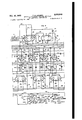
- FIG. 1 shows in block form a diagrammatic view the proposed multiplex system
- Fig. 2 shows arelative arrangement of the views disclosing'the transmitting station
- Figs. 3, 4, and 5 show in detail the'apparatus and circuits comprising thetransmitting station; Fig. .6..shows a relative arrangement of the views disclosing the receivingstation;
- Figs. '7, 8,.and 9 show in detail the apparatus and circuits comprising the receiving station; Fig. l0--shows thevoltage wave characteristics,
- Fig. 11 shows the voltage wave characteristics and relative timing of certain operational se-' quences of the receivin apparatus.
- Fig. 1 it is possible to obtain a general idea of the component parts of the apparatus and their inter-relation with respect to each other forming the multiplex system.
- a standard frequency generator is provided and is connected to the electronic transmitter; likewise two tape transmitters are connected to the electronic transmitter.
- the electronic transmitter itself may, in general, be described as being comprised of three parts, said parts being a pulse generator, an electronic distributor, and transmitting apparatus including a plurality of relay tubes operating in conjunction with the tape transmitters and the electronic distributor.
- the general description of the receiving station, as shown in Fig. 1, will be postponed until a full description has been made with respect to the transmitter station and just prior to the description of the receiving station.
- the generated standard frequency has the customary A. C. voltage characteristic of a sine wave.
- Pulse generator The voltage generated by th standard frequency generator is passed to a pulse generator which, in general, comprises an amplifier indicated generally by the numeral 22, a rectifier indicated generally by the numeral 23, and an amplifier indicated generally by the numeral 26.
- a grounded battery 26 supplies D. C. potential over a common conductor 21 to junction point 28 and thence over a conductor 29 and through load resistors 3
- the cathodes 33 of the tube 22 are connected to a common conductor 34 which is grounded at 35.
- the standard frequency which is generated by the unit 2i and which is in the form of a sine wave is fed over conductor 37 to the control grid 38 of the left-hand section of the vacuum amplifier triode tube 22 which may be of the 6SN7 type.
- the resulting amplification process, through the operation of this tube, results in an amplified voltage such as disclosed as the curve 39 in Fig. 10.
- the amplified output of the left-hand section of tube 22 is fed by means of a conductor 41 to the left-hand section of the twin diode rectifier tube 23 which may be of the 6H6 type.
- a coupling condenser 42 is provided between the output circuit of the left-hand section of the amplifier tube 22 and the cathode 43 of the lefthand section of the twin diode tube 23, to which the above-mentioned output is directed, in order to prevent direct current being fed to the cathode 43 from the D. C. source over conductor 29,
- the grid 41 is normally at zero bias and since only a comparatively small part of the applied negative grid voltage (output of left-hand section of rectifier tube 23) is required to bias the grid 41 to the plate current cut-off value, there results an output which is in the form of a square wave, as shown by voltage curve 49 in Fig. 10.
- a wave having pulse characteristics as shown as 50 in Fig. 10 will be impressed on the cathode 43 of the right-hand sectionof the tube 23.
- the condenser 52 precludes potential from the D. C; source from reaching the cathode 43.
- the tube 23 rectifies the input voltage, removing the positive half of the wave and passing the negative half only, as shown as 53 in Fig. 10, over a conductor 54 to a potentiometer indicated generally by the numeral 56.
- the negative half of the wave then passes over a conductor 57 to the control grid 58 of a triode tube 24 which may be of the 6J5 type.
- the plate of the tube 24 is supplied with direct current from the battery source 26 over the common conductor 21 to the junction point 28, over a common conductor 53 to a junction point 6
- the cathode of the triode tube 24 is supplied with ground from 35.
- the positive output voltage passes from the plate over a conductor 64, through a coupling condenser 66, and over a common conductor 67 to the control grids of a plurality of electron tubes in the distributor, as will be described hereinafter.
- the coupling condenser 66 is provided so that the direct current supplied to the plate of the tube 24, through the resistance element 62, may not pass over the common conductor 6'! to the control grids of the electron tubes in the distributor but instead will be precluded from so doing by means of the condenser 66.
- cathodes 33 of tube 22, cathodes 4,. of tube 23, and the cathode of 'the'aconductor '31 is coupled to the grid arrangement because of the andascreen grid "tubafl Suiterall; grdunded rover :common; conductor-.iihto .zthezcommon; grounding point .35. Itis totz'besgfurther :notdithat :theioutput of thestandardt frequency generator 2 I ,1 after it. passes over 38iby means of aresistance-elem-ent 69.
- Figs. 3, 4, and 5, arranged in" the order shown in Fig. 2.
- it is comprised of ten gas filled tubes 15 tot i, inclusive; which as previously mentioned, may be of the-2050*thyratron type tubes.
- the present system'disclosed is a two channel multiplex system. "However,- in the event that a four channel systemwere to be used, the-number-of distributor-"tubes would be increased accordingly to twenty. In the instant application'there is one "tube 'providedfor each character impulse for'the two channels. making ten in number.
- Each of the tubes, 15 to 8d, inclusive is provided with a plate oranode 86,
- the plateonanode 96 of each of the tubes 15 to- 84-, inclusive is connected over a conductor 9i and through a 'load'resistor 92 to the common conductors 1'2! and 59,-previously referred to as leading'from the D. C. source 25.
- the anodes 89 of 'thetubes willnormally have a highpositive ptentia1 impressed thereon.
- the cathode. Bl of each" of, the tubes is connected by means of a conductor 93'ian-d through an individual resistor '9'4to a common'conductor 96 which is grounded at"9l.
- the control grid 88 of each ofrthe tubes is, connected by means of, a short conductor .98 to a conductor 99, connectedlthrougha condenser I0! to the, common conductor 67, previously reierred to.
- the conductor 99 has a resistance I92 thereinwhi-ch is on the opposite side of a junction point 193 from the anode lead 98.
- the end. of the, conductor 99 closest to the resistor I92 is connected to.
- a common conductor I95 which is similarly connected with respect to all of the tubes.
- Thescreengridflil of eachofthetubes is oonnectedby means of conductor Ills directl to the-cathode 18], both of which .arebyepassed to 7 ground. through a condenser "Hi1.
- cathode i l oithe varioustubes is connected by means of the-associated conductor 93 overa conductor E98 having a resistor I99 therein and through a second resistor II I- to ia common conductor II2 extending to all of the tubes and similarly connected.
- a short conductor I I3 extends from the, conductor It? andlea-ds to the controlgrid of a'twin triode relaytube.l,5 3,.for a reason which will be described hereinafter.
- control grids 8B niche-individualtubes are normally :biased with ten tubes-areprovid-e'd in the instant a cathodefl'l, a control grid 88 a negative voltage which is'the-difierence between theIR- drop in the resistor I92 and the negative voltage of the conductor I94.
- the biasing circuit may be traced from the negative grounded battery IZI, over the conductor H9, through the resistor H9 to the junction point I29, over the conductor I22, over the conductor IM, over the conductor 99 and through the resistor 292 to the junction point see, over a conductor I49, through the resistors I28 and izfiassociated with the tenth tubeM, over the conductor 93 andxthrough the cathode load resistor 94 (tube 84),, and through the common conductor 96- to ground at 9'1.
- the screen e'ridsil-S and their conductorsgififi are connected to the cathode 8'! by means of a conductor I2 3 extending therebetween.
- Theconvductor lid and the cathode 3? are connected through a resistor 126 to junction point I21 and through a second resistor 23 to the conductor 99 associatedwith the succeeding tube 19.
- the junction point I2? is connected by means of a conductor IE9 and through a condenser ISI to the common grounded conductor 96, previously mentioned.
- the anodes 85 of successive tubes such as T and I6 are interconnected by means of a conductor I32 having a condenser I33 therein.
- a conductor IM is provided which connects the conductor 9i ofthe plate 8% of tube through a condenser I35, similar to condensers I33, to the conductor iii of the plate 86 associated with the tenth tube E i, for a purpose to be later described.
- the conductor 9! associated with the anode 86 of the tube '55 is connected by means of a resistor I31 to a conductor i38 which extends to the control grid of a triode tube which will be described more fully hereinafter.
- the conductor I38 and resistor I 3'! are also connected through a resistor 539 to the conductor I34, previously described.
- the conductor 9i extending from the plate of the fifth tube 79 is also connected by means of a resistor id! to a conductor l izwhich extends to the control grid of a second triode tube also to be utilized in a manner and for a purpose as will be described hereinafter.
- the resistor I4! and conductor I42 are connected through a resistor N53 to the conductor 9i associated with the plate d9 of the sixth tube 89.
- a condenser his is provided which is connected between the common grounded conductor and the common conductor I94.
- a start key M5 is connected to the conductor 99 associated with the control grid 88 of the tenth :tube 83 and serves, when the key is depressed, to
- the conductor M2 is connected by means of a conductor M8 to the common conductor H2, previously described.
- the operation or firing of the tube 84 may be 'traced in an electrical circuit from positive battery 28, over the common conductor 27:, over the common conductor 58, through the load re sistor 92 and the conductor iiI associated with the anode 83 of the tube 84, to the cathode 8"! of this tube (which is now conducting), over the conductor .13, through the cathode load resistor 8 and over the common conductor 96 to ground at 8?.
- Such a circuit will be established and the tube will continue to fire until such time as external means are utilized to cause the tube to be extinguished.
- a condenser I35 is connected to a conductor I35 which joins the anode conductors 9
- the condenser I35 will be in an uncharged condition due to the fact that the conductors 8i of both tubes '35 and 8:3 will be impressed with a positive charge from the positive battery 26, as previously described.
- the tube 84 operates or fires, as just described, there will be a drop in the potential across the anode load resistor 82 associated with the tube 84 which willv result in the condenser I35 becoming charged.
- control grids '88 of the various tubes are biased negatively by means of a circuit which includes the cathode and cathode load resistor of the preceding tube.
- the firing of the tube 84 and the resultant electrical circuit, which was described as passing through the tube, will have the effect of adding positive voltage to the negative battery circuit, which may be traced through the cathode 87 of the tube 84, over the conductor 93, through the cathode load resistor 84, over the common conductor 96 to ground at 91.
- the control grid 88 of tube 15 will be less negative y biased.
- the next incoming positive pulse such as shown at 63 in Fig. 1c, of the pulse generator, previously described, passes over the common conductor 61 and over the conductors 99 and 98 to all of the grids 88 of the various tubes.
- the biasing voltage of the grid which has been conditioned will be reduced from the conditioning value to a sufficiently low voltage to fire that particular tube.
- bias potential to the control grid 88 of the tube "I5 this tube will operate or fire.
- each of the conclusters 99 leading from the common conductor Ii! to the grid 88 is provided with a blocking condenser I85.
- This condenser allows the positive pulse from the pulse generator to pass over the conductor 89 to the grid 88 but prevents the D. C. biasing voltage from being fed back to the common conductor 67.
- the potential on the anode 88 of this tube which has been reduced due to the IR drop across the load resistor 92 results in a discharge of the condenser I35 which has previously been described as being charged.
- the path of discharge of the condenser I35 may be traced from the condenser, over the conductor 9
- pulsemeceivedonlthat gridiron Such-war delay networkiis utilizedxin order. to precludeea tube from firingi-at a tim wvhenit is being-ccnditioned.
- the filtercondenser I 44 previously cdescribedi asibeing connected between the common. conduc-v tors; 95.; and i I M; has. been included .in the vcir-.
- each pair otassociated I tubes: 15 etc I84,- inclusive are provided. ,with a condenser I33 between I the plates. 86 thereof. These condensers are isimilarito-and operate in.
- the transmitting apparatus includedin the present- multiplex systerncontemplates theuse of an A tape transmitter 5 indicated generall by; the-numeral I5 I and-a- B tape transmitter indicated-general1yby-the numeral 1 I52;
- Five twin triode tubes I53 toIS'I; inclusive; are provided as is a transmitting relay tube I59;
- A-pair of controltubes -I 6 I and I 62 areasseciated with the -A tape transmitterd 5 I and a pair of -simi-- 1ar-controltubes I 63 and I Etareassociated -with-- the B tapetransmitten-I 52
- ntrol grids I iii-and I II are connected -by -rneans -of --conductors I I 3 "to the output circuit of the distributortubes 1 5 to 84, inclusive, through the resistors I QQ-and over the conductors I98.
- the cathodes I66: and- I'IIJ of the: triode tubes are-connected.- by means of -aconductor -I I3 mentioned; the co tothe commonnconductor. 96. whichztis; grounded .1; atv .91.;
- I as -and. the anode. I 68, of thetube.
- I 55 J areQc n-J nectedpbyimeansnof conductors I15 to;.II9,' inclu-H, v rt .fiv ontactnpoints, indicated icy-the. ..nu- 1st! to t inclusivez respectively, of a, socket I s I. iwhicnis associated w h he. fA anetrans: mitter.
- the tube IBI is further provided-with.
- the tube I63 has a. controlgr'id zcs which is connected over, conductor 209 to. the, conductor I38, previously described.
- Aconductor H3 is inserted connecting the cathode 2
- The, tube I63 is similarly provided with a cathode.
- conductor 223 havinga resistor 2'24 therein which is, connected to the conductor I 32; previously mentioned, and a conductor 226 which is connectedtoa grid22l'ofthe control tube I52.
- control tube IE2 also has a cathode 228'which grounded at 229. Ina'smuc h as the connections of the control tube its associated with the e tape transmitter I52 are similar to those as described for the control tube.lt2, further description of them is not deemed necessary.
- The. triode transmitterv tube I59 has. a control grid 23I which is con-. nectedby..means of a. conductor. 232 to junction; point 233 which has-branching therefrom a con- An, eighth contact point is cononductor I3to junction point I94 ductor 234 having a resistor 236 therein which-is connectedto the conductor I96 at junction point 231 and a conductor 238 having a resistor 239 therein which is connected to the conductor II9 immediately adjacent the negative grounded battery I 2!.
- the anode 24I of the tube I59 is connected over a conductor 242 to a positive battery 243 and thence over conductor 244 to the resistor 246 forming part of a potentiometer, indicated generally by the numeral 241.
- the resistor 246 is connected through a resistor 248, over a conductor 249, and through a switch 250 to a conductor 25I leading from the cathode 252 of the tube I59.
- the conductors 249 and 25I are grounded at 253.
- a negative battery 255 is also provided for polar operation which is placed in the circuit in the event that the switch 250 is moved to its upward position (Fig. 4) rather than its lower position, as shown for neutral operation.
- the movable member of the potentiometer 241 is connected by means of conductor 254 to one contact member 256 of a signal output jack, the opposite contact member 251 of which is grounded at 258,
- the tape transmitters I5I and I52 are each provided with a plug 26I having eight contact points thereon which is adapted to cooperate with the socket I8I of the A tape transmitter and the socket I88 of the B tape transmitter.
- the sensing controlled contacts of the tape transmitters have been shown schematically but consist of five movable contacts 263 to 261, inclusive, which are connected over conductors bearing the same identifying numerals to the contact points I to 5, inclusive, respectively of the plug 26L
- a bus bar 269 is provided which cooperates with all of the movable contacts and which is connected over conductor 216 to the No. 8 contact point of the plug 26I.
- a tape stepping solenoid 212 is provided, one side of whose winding is connected over conductor 213 to the No.
- the tape transmitters I5I and I52 may be of any commercial type, many of which are known in the art, the instant embodiment contemplates the use of a tape sensing mechanism such as that disclosed in U. S. Patent 2,418,928, issued April 15, 1947, to W. R. Gemmel (excepting mechanical distributor and dual sensing device control), or in Bulletin No. 141, Issue 3, issued by the Teletype Corporation, Chicago, Illinois, in March 1942.
- the switch 216 has been provided in order to be able to control manually the operation of the tape transmitter I5I.
- the output circuit of the distributor tubes 15 to 84, inclusive are each connected by means of the conductor 93, the conductor I68 having the resistor I69 therein. and the conductor II3 to the control grids I61 or ill of the twin triode tubes I53 to I51, inclusive. Assuming in the instant example that the tube 15 is in its unoperated or nonconducting condition, the grid I61 of the left-hand section of the tube I53 will be biased to a negative value.
- Such negative bias occurs due to the IR drop across the resistor III and the negative battery I2I of a circuit which may be traced from ground at 91, over the conductor 96, through the resistor 94, over the conductor I68, through the resistor I09, through the resistor III, over the conductor II2, and over the conductor H9 to grounded negative battery I2I. Under this condition with grid I61 of the tube I53 being biased negatively beyond its cutoii value, the tube I53 will be nonconducting.
- the output voltage of the tube 15 may be traced, as previously described, from the cathode 81, through the conductor 93 and the resistor 94. Due to the addition of such voltage there will result a further potential drop across the resistor 94 which will cause an increased IR drop across the re-.
- the contact point 263 is in, its spacing position out of engagement with the bus bar 269.
- the control grid 23I of the transmitter tube I59 will have a zero grid voltage.
- the transmitting tube I59 controls the transmission of outgoing signals to the signaling channel, not shown except schematically in Fig. 1, thefollowing condition will exist as a result of the zero condition of the grid 23I.
- the tube I59 will be conducting and a circuit may be traced from ground 253 through the switch 250 which is in its lower-position for neutral operation, over the conductor 249, through the resistor 248, through the resistor 249 forming part of the potentiometer 241, over the conductor 244, through the positive battery 243, over the conductor242 to the anode 24I, through the tube I59 which is now conducting, to the cathode 252 and over the conductor 25I to ground at 253.
- a circuit may also be traced from ground 258, through the one contact element 251 of the signal output jack, through the second contact element 259 thereof, over'the'conductor 254 to the variable member of the potentiometer 241, through-the resistor- 246 with which it is in engagement, over the conductor 244, through the positive battery 243, over the conductor 242 to the anod 24I of the transmitting tube I59, through the tube I59 which is now conducting to the cathode 252 thereof, and over the conductor 25I to ground at 253.
- a negative line signal will be transmitted from the output jack exemplified by the contact members 256 and 251 to the signaling channel.
- Such neutral negative line signal occurs, as described above, when there is a spacing condition existing.
- an electrical circuit may be traced from ground at 91, over the common conductor-Bfi, over the conductor I13 to the cathode I10'of the tube I53, through the tube I53 to the anode I12, over the conductor I16 to the No. 2 contact pointoi the socket IBI, to the No. 2 .contact point of the plug 26! which will be in engagement therewith, over the conductor 294 to the contact point its now in engagement with the bus bar 299, through the bus bar 293 and over the conductor 219to the No. 8 contact point of the plug 26! to the No.
- the switch 259 should be positioned in engagement with its upper contact point, rather than in engagement with its lower contact point as disclosed in Fig. 4 of the drawings.
- the tube I59 will be conducting and an electrical circuit may be traced similar to that traced above with the exception that it must be traced through the negative grounded battery 295.
- the negative grounded battery 255 and the constants of the resistors 249 and 249 a negative signal will still be transmitted over the signaling channel through the, jack exemplified by the contact elements 253 and 291.
- the first five tube elements cooperate with the A tape transmitter and the transmitting tube to transmit coded impulses over the signaling channel
- the second five distributor tubes cooperate with the B tape transmitter I52 and the remaining five tube elements of the relay tubes, to cause signaling impulses to be transmitted from the transmitter tube I59 over the signaling channel which are representative of the intelligence in the B channel.
- control tubes [BI and I62 associated with the A tape transmitter I5I and the control tubes I63 and IE4 associated with the B tape transmitter I52. These tubes, which operate under the control of distributor tubes, are utilized to step the tape in the tape transmitter in a manner which will now be described. Inasmuch as the control tube I6! and I 62 operate in conjunction with the A tape transmitter and the control tubes I03 and I54 operate in a similar manner with respect to the B tape transmitter, description will be made of the operation of the former tubes only.
- control tubes are conditioned by and under the control of the fifth and sixth distributor tubes I9 and as for the control tubes IfiI and I62, whereas the control tubes I53 and I54 associated with the B tape transmitter I52 are conditioned byand under the control of the tenth tube 34 and the first tube I5.
- the voltage of grid 204 of the control tube I6I will be zero and this tube will be conducting.
- Such zero condition on the control grid 204 may be traced from positive grounded battery 26, over the conductor 21, through the resistor 92 associated with the tube I9, through the resistor MI, and over the conductor I42, through resistor 201, over the conductor I40, and over the conductor Hi! to negative grounded battery IZI.
- a second circuit may also be traced which instead of going through the resistor 92 associated'with the tube i9, passes through the resistor 92 associated with the tube 80 and through the resistor I43 to the conductor I42.
- the grid voltage of the tube I6I will be zero and this tube will conduct over a circuit which may be traced from grounded positive battery 25, over the conductor 21, over the conductor 203' and through the resistor 202 to the anode 20!, and through the tube I6I to the cathode 2H and to ground at 2I2.
- the control tube I62 Under the condition just described with the distributor tubes 79 and 80 not firing and with the tube ieI conducting, the control tube I62 will not be conducting because the control grid 221 thereof will be biased negatively. The reason for such negative bias at this time is because of the potential drop across the resistor 202 at the time that the tube IEI is conducting.
- the circuit for controlling the bias of the grid of the tube I62 may be traced from negative grounded battery I 2! over the conductor H9, over the conductor I48, over the conductor 223 and through the resistor 224, through the resistor 22 I, over the conduct-or 2 I 9, through the resistor 202, over the conductor 203 to the common conductor 21, over the common conductor 21 to positive grounded battery 26.
- control tubes l6! and I62 are under the joint control of the distributor tubes 19 and 80.
- the distributor tube 19 will condition the succeeding tube 80 for firing which, when that occurs, causes the extinguishment of the preceeding tube 19'. Therefore, assuming now that the tube [9 is no longer firing but instead the tube 8B is firing, a similar circuit and condition may be traced for causing the tube It! to be nonconducting, the tube I62 to be conducting, and the solenoid 212 to be energized,
- the joint control of these two tubes for causing the tape stepping operation is necessary because of the duration of time consumed in, the tape stepping operation.
- condensers 214 and H8 were described as being between the cathode and grid of the control. tubes I6 I: and I363. Such condensers have been provided because, as previously described, the operation of the distributor tubes is substantially instantaneous and, therefore by providing these condensers an abrupt application of voltage to the solenoid 212 may be prevented. Thus, the voltage impressed thereto will be somewhat smoothed out inorder to achieve more satisfactory operation thereof.
- the electronic distributor as exemplified by the thyratron tubes 15 to 84, inclusive, when once started operates in timed succession with the positive pulses generated by the pulse generator. Likewise, it hasbeen described. how the tubes operate or fire through the conditioning by the preceding tube and upon such firing causes the extinguishment of that preceding tube.
- a pair of tape transmitters are provided which have their sensing contacts connected to one element each of a plurality of relay tubes.
- An.- other element of the relay tube is conditioned by the output of an individual distributor tube to which it is connected sothat a particular relay tube will conductor not conduct depending on the joint operation of the associated distributor tube and the tape sensing contact, depending also on whether the contact is. in marking or spacing condition.
- a transmitting tube is provided, as described, which is under the control of the relay tubes, and which through successive operations or nonoperations, depending on whether marking 0r spacing selections are set up in the tape sensing contacts, causes permutation.
- code signals comprised of five impulses each to be transmitted over the signaling channel.
- Receiving station By referring to Fig. 1, the various component parts of the receiving station have been shown diagrammatically and comp-rise, in general, a standard frequency generator, a corrector network, a phase shift network, an electronic receiving unit, a multiplex printer, and a start-stop printer operating in conjunction with a multiplex to start-stop converter. It is obvious that two multiplex printers could be utilized instead of a start-stop printer, but for description purposes, in order toshow how start-stop apparatus could be adapted to such a system, the disclosed apparatus is included. It is to be noted that both the electronic receiver and the corrector network are connected to the signaling channel over which permutation code signals, originating from the transmitting station just described, are received.
- such apparatus may be broken down into component parts which include a pulse generator, an electronic distributor and selector mechanism which will be described hereinafter separately, as was done with respect to the component parts of. the transmittingstation.
- Standard frequency generator A standard frequency generator, indicated generally by the numeral 30!, has been provided which operates similarly to the one disclosed with respect to the transmitting station and which is well known in the art and obtainable commercially. Inview of the generator 301 being standardequipment, no further description thereof is necessary other than to say that such generator is preferably crystal controlled for a reason-which will be described hereinafter.
- the output of the generator Eel is, as usual. with such units, of a sine wave characteristic.
- Corrector network which has been indicated generally by the numeral 302 is provided, which is connected to-the signaling channel by means of aconductor 363 and to the standard frequency generator 3M by means of a conductor 304.
- Phase shift network A phase shift network indicated generally by the numeral 333 has been provided and is connected to the standard frequency generator by means of a conductor 331 in order to manually shift the phase of the sine wave generated by the standard frequency generator 30!, prior to its.
- the pulse generator utilized at the receiving tation and which is exemplified by amplifier tube 333, rectifier tube 389 and triode tube 3! is connected to the phase shift network 306 by means of a conductor 315.
- a. sine wave is transmitted over the conductor M to the lefthand element of the amplifier tube 388 from whence it is rectified and amplified similarly to that shown in progressive steps in Fig. 10, identically as was done at the transmitting station.
- a condenser 3!2 has been provided in order to increase the output of the pulse generator.
- the output of the triode tube 3! i which has a similar wave characteristic to that shown as 63 in Fig. is impressed over a conductor 313 to a common conductor 3! 4 and thence is impressed on all of the control grids of the tubes of the electronic distributor.
- the selector apparatus includes, in general, a plurality of gas filled thyratron tubes 33! to 340, inclusive, and two similar gas filled sixth pulse tubes 342 and 343.
- a pair of relays indicated generally by the numerals 344 and 346 are provided which operate in a manner and for a purpose which will be described hereinafter.
- the control grid 341 of each of these tubes is connected over a conductor 348 and through a condenser 349 to junction point 35! with the conduct-or 328, previously mentioned, leading from the output of the distributor tubes.
- the cathode 352 of each of these tubes is connected over a common conductor 353 to junction point 422 and thence to ground at 354.
- the screen grid 356 of each of the tubes is connected to a common conductor 351 which is connected by means of a conductor 358 to the one contact member 359 of a signaling input jack having the other contact element 36! connected over a conductor 362 to junction point 422 and thence to ground at 354.
- the input jack receives the signal impulses from the signaling channel.
- a line terminating resistor 353 is provided between the conductors 358 and 362 for a purpose which is well known to the telegraph art.
- the anodes 364 of the various selector tubes 33! to 335, inclusive, are connected through the individual load resistors 366 and over conductors 361 to 31!, inclusive, respectively, to five contact points Nos. to 5, inclusive, of a socket 313.
- a sixth contact point of the socket 313 is connected over a conductor 314 and through a resistor 315 to an anode 316 of the sixth pulse tube 343, previously mentioned.
- a seventh contact point of the socket 313 is connected over a conductor 311 and through a condenser 318 to junctionpoint 319 and thence over conductor 38! to grounded positive battery 382.
- the condenser 318 is provided to prevent sparking of the contacts of the relays 344 and 346.
- selector tubes 335 to 340, inclusive are connected similarly to that described for the tubes 33! to 335, inclusive, with the exception that they terminate in a socket 383 instead of socket 313, no further description will be made thereof. It is to be noted, however, that the sixth contact point of the socket 383 is connected to the anode of the sixth pulse tube 342 and the seventh contact point is connected through the armature of the relay 344 to the positive battery 382.
- the five tubes 33! to 335, sive to the A the tubes 336 inclusive, are responchannel incoming signals, whereas to 348, inclusive, are responsive to channel signals, in a manner to be described hereinafter.
- the sixth pulse tube 342 operates in conjunction with the first distributor tube 3!6 whereas the sixth pulse tube 343 operates in conjunction with the sixth distributor tube 32!.
- conductor 393 is also connected beyond junction a. conductor 399, over conductor 431 to a common conductor 492 whichis connected by means of resistors 493 to the conductor 348 associated with the control grid, of each of the tubes 331 to 3411, inclusive.
- the conductor 401 is formed with the movable member 494 of. a potentiometer, the resistor 436 of which is connected through resistor 4131 to ground at 493.
- the opposite side of the resistor 436 of the potentiometer is connected through resistor 469 to a common conductor 411 which is connected over conductor 412 to grounded negative battery 413.
- the conductor 411 is connected over conductor 414 and through condenser 416 therein. to the junction point 411, intermediate the resistor 491 and ground at 4118.
- the sixth pulse tube 343 has a screen grid 418 which is connected by means of conductors 419 and 42 I. to the conductor 362,v thence to its junction point. 422 with the conductor '353,and to ground. at 354, as is the screen grid of the tube 342.
- the cathode 423 of the tube 343 is connected. over conductor 424 to ground at 354.
- the relay indicated generally by the numeral 346 is formed of a winding 426, one end of which is. connected through resistor 421 and over conductor 428 to the conductor 314, previously mentioned, and the opposite side of the winding is connected over conductor 429 also to the'conductor 314'. It is to be noted, however, that the conductors 423 and 429 are connected to the conductor 314onopposite sides of the resistor 315.
- a condenser 4.31 provided between the conductors 428 and 429 immediately adjacent the winding 423.
- 'An armature 432 is provided for the relay 345 which is connected over conductor 433 to the conductor 311, previously described.
- a plug 441' is provided which cooperates with the socket 313 and which has the contact points 1 to 5, inclusive, connected over conductors 442 to 446, inclusive, respectively, to one side of the windings. of individual magnets 449 to 452, inclusive, respectively, of a multiplex printer indicated generally by the numeral 453.
- Such a multiplex printer may be similar to that. disclosed in U. S. Patent No. 1,665,594, issued to H. L. Krum on April 10, 1928.
- the opposite side of the windings of the magnets 448 to 452, inclusive are connected over a commonconductor 454, to the No. 1 contact point of the plug 441.
- The, No. 6 contact point of the plug 441 is connected over a conductor 456 to one side of the winding of a sixth magnet 451, the opposite side of which is connected to the common conductor 454.
- A. plug 456 is provided to associate with the socket 383, previously mentioned as being confrequency generator 391,
- the contact points of the plug 458 are connected by means of conductors to the multiplex side of a multiplex to start-stop converter indicated generally by the numeral 459.
- vSuch a multiplex to start-stop converter as contemplated in the instant description includes a start-stop side also which impresses the converted signals over a conductor 461 to a single magnet start-stop printer, indicated generally by the numeral 462.
- the multiplex tostart-stop converter 459 may be'similar to that disclosed in'U. S. Patent No. 2,382,596, issued on August 14, 1945, in the name of W. J. Zenner.
- the single magnet start-stop printer 462 may be of the type disclosed in U. S. Patent No. 1,904,164, issued on April 18, 1933, to S. Morton et al.
- selector apparatus In the following description of the selector apparatus, it is to be assumed that the standard the corrector-network 392, the phase shift network 336, and the pulse generator, as exemplified b-y tubes 398, 399, and 311 arefunctioning properly to present a positive pulse over the output circuit of the tube 31 1 to the conductor 313' and to the common conductor 314, similar to the positive pulse disclosed on the voltage curve 33 of Fig. 10'. "Likewise, it is to be assumed that this positive pulse, which is presented to the control grids of the electronic distributor tubes 316 to 325, inclusive, causesthe operation of these tubes successively in a manner. which has been described with respect to the electronic distributor at the transmitting station.
- the incoming signal from the signaling channel to the signal input jack is composed of a code signal having a spacing and marking characteristic for the first two impulses, as described with respect to the transmitting station.
- Such input wave characteristics may be seen by reference to curve 463 in Fig. 11, wherein alternatespacing and markingv impulses are shown.
- the distributor tubes can be caused to fire variably out of phase with respect to the incoming signals, a may be seen by comparing curves 329 and 463 of Fig. 11.
- a circuit may be traced. from ground at 498, through the resistor 401, through the resistor 496 of the potentiometer,. through the resistor 439, over the conductor 4'11, and over the conductor 412 to negative grounded battery 413.
- This circuit acts to bias the control grid 341 of the selector tube 331 negatively in such a manner that the tube will not fire.
- the control grid-341 of the selector tube 332 will be reduced to' zero voltage in a. manner as just described with respect to the selector tube 33!.
- the marking condition on the signaling channel is a zero condition, as previously described, there will be no negative bias on the screen grid 356 thereof from the conductors 358 and 351.
- both the control grid'341 and the screen grid 356 will have a zero voltage value and under such a condition the selector tube 332 will fire.
- an electrical circuit may be traced from ground at 354 over the conductor 353 to the cathode 352 of the selector tube 332, through the tube which is now firing to the anode 364, through theresistor 366, and over the conductor 368 to the No. 2 contact point of the socket 313 to the No. 2 contact point of the plug 44!, over the conductor 443, through the winding of the magnet 449, through the common conductor 454 to-the No. 1 contact point of the plug 44! and to the No.
- the control grid 396 of the sixth pulse tube 343 ' is biased negatively by a potential developed across the potentiometer at point 404 and which may be traced through-the movable member 404 of the potentiometer, over the conductor 46!, over the conductor 399 to the junction point 460, over the conductor 393 and through the resistor 394.
- the biasing potential developed across the potentiometer results from a circuit which may be traced from nega-
Landscapes
- Engineering & Computer Science (AREA)
- Signal Processing (AREA)
- Computer Networks & Wireless Communication (AREA)
- Amplifiers (AREA)
- Electrotherapy Devices (AREA)
- Selective Calling Equipment (AREA)
Description
Dec. 30, 1952 T. A. HANSEN MULTIPLEX TELEGRAPH RECEIVER EMPLOYING AN ELECTRONIC DISTRIBUTOR Original Filed May 28, 1945 8 Sheets-Sheet 1 18.255 0: 65-525 55:: 6 55:: moEw zou mwktzmzh ECSwEE 6.5-585 =9. op x5252: 5235. v 52256 5.5.555 220 o FF u M. 33536 22053 6 O- PwZ VEOBPMZ im U95 @2858 105550 35:35. 3355 "82523 5552;; c5355 INVENTOR *rue'ooom-z A. HANSEN ATTORNEY 2,623,948 ECEIVER EMPLOYING AN ELECTRONIC DISTRIBUTOR Original Filed May 28, 1945 Dec. 30, 1952 'r. A. HANSEN MULTIPLEX TELEGRAPH R 8 Sheets-Sheet 2 INVENTOR THEODORE A. muses ATTORNEY FIG.3
Dec. 30, 1952 T. A. HANSEN 2,623,948
MULTIPLEX TELEGRAPH RECEIVER EMPLOYING AN ELECTRONIC DISTRIBUTOR Original Filed May 28, 1945 8 Sheets-Sheet 3 STANDARD FREQUENCY GENERATOR 246 J: g oun=m 25 INVENTOR THEODORE A. HANSEN IPZSS 0 BY 249 TORNEY Dec. 30, 1952 2,623,948
HANSEN MULTIPLEX TELEGRAPH RECEIVER EMPLOYING AN ELECTRONIC DISTRIBUTOR 8 Sheets-Sheet 4 Original Filed May 28, 1945 F's 5 INVENTOR THEODORE A. HANSEN TOR NEY 2,623,948 EMPLOYING AN ELECTRONIC DISTRIBUTOR Original Filed May 28, 1945 Dec. 30, 1952 T. A. HANSEN MULTIPLEX TELEGRAPH RECEIVER 8 Sheets-Sheet 5 FIG.
FIG.
6 4 MN MW YR R 0C0 OK RNT R A E A T D U R C O N E E W A Q N R T T E E R E S R G O N F C 3 N O N TMM N l S F FIG. 6
INVENTOR THEODORE A. HANSEN FIG. 7 y? ATTORNEY Dec. 30, 1952 T A H E 2,623,948
MULTIPLEX TELEGRAPH RECEIVER EMPLOYING AN ELECTRONIC DISTRIBUTOR Original Filed May 28, 1945 8 Sheets-Sheet 6 INVENTOR THEODOR E A. HANSEN ATTORNEY Dec. 30, 1952 2,623,948
T. HANSEN MULTIPLEX TELEGRAPH RECEIVER EMPLOYING AN ELECTRONIC DISTRIBUTOR 8 Sheets-Sheet 7 Original Filed May 28, 1945 353 INVENTOR THEODORE A. HANSEN ATTORNEY Dec. 30, 1952 r. A. HANSEN MULTIPLEX TELEGRAPH R 2,623,948 ECEIVER EMPLOYING AN ELECTRONIC DISTRIBUTOR Original Filed May 28, 1945 8 Sheets-Sheet 8 INVENTOR THEODO R E A. HANSEN TTORNEY r. pulse. generator.
. voltage and'impress it on the control grid of the .stubes of. an'electronicdistributor. sThe electronic distributor-is so constructedthat its tubes operate or fire successively,.only one tube being operative atone time. .-tributor controls a series of secondary tubes -..which.-are conjointly underthe control of a tape ...-.-transmitter;....The secondary tubes, each. under the. joint control of ....tap e..transmitter, pause impulses to be.
r .to .astransmittingirelay. tube from. whence they Patented Dec. 30, 1952 UNITED f STATES TENT OFFICE 'MULTIPLEX TELEGRAPH RECEIVER EM- PLOYING AN ELECTRONIC DISTRIBUTOR Theodore A. Hansen, Park Ridge, 111., assignor to Teletype Corporation, Chicago, 111., a corporation of Delaware Original application May 28, 1945, Serial No. r 596,295. Divided and. this application December 15, 1948, Serial No. 65,438
5 Claims.
""The present invention pertains to telegraph "apparatus, and more particularly to receiving apmparatus for use in multiplex systems.
This application is a division of copending ap- 'l 'plication Serial No. 596,295, filed on May 28, 1945.
'Inpresent multiplex telegraph systems, and
' apparatus. utilized therein, mechanical means are utilized for the transmission and reception of the intelligence signals. While these systems operate satisfactorily there is a maximum speed The receiving station comprises a standard frequency generating apparatus and a pulse. generator controlling a distributor in a manner similar to that mentioned above. A series of selectortubes'are provided which are under the joint control of the distributor and the incoming code signals. The selector tubes control the code magat which they will operate which is relatively low. At the present time, with the trend toward I 'higher speedoperation, it becomes necessary to "provide apparatus and systems which will op- 1'-erate at greater speeds and which will not have a limiting maximumspeed that is relatively low.
Accordingly, a primary objective of this invention-is -to provide high-speed apparatus for use in a multiplex telegraphsystem.
further object is to provide electronic ap- 'paratus for achieving such-speed.
Another object of the invention is to provide r -telegraph receiving apparatus utilizing electronic "components.
Yet another object of the invention is to elimi- -nate as fullyas possible all mechanical and movingparts and to substitute therefor inertialess members of the tubevariety.
A'still furtherobject ofthe invention is to provide an electronic distributor in the receiving 'apparatus.
' Another object of the invention is to provide A still further object of the invention is to :;.-;;provide electronic receiving apparatus which may be:easily. oriented and phased in theoperating system.
- .Intgeneral, the systernzcontemplates apparatus at;both the: transmitting :and; receiving stations .-.comprising,- as fully as possible, electronic ap- -paratus..
astandard frequency generator to initiate voltage :The transmitting station utilizes a are presented to the tubes of a which; amplify and rectify the impulses which .The-output of the dis- .a distributor tube and the presented aretransmitted over asignaling. channeL. A tube iswproyided .to.cause the tapetransmitter to step I .I .the tape. afterflthe. co (id-signal. is transmitted.
nets of a multiplex printer or the magnets of an extension arm system for converting multiplex to start-stop code signals. Sixth pulse control tubes are provided which are under the control of the distributor and which control the printing operation of the printer and are utilized to extinguish any of the selector tubes which may have been operated. The receiving station is also provided with a corrector network and a phase shift network in order to synchronizeand phase the receiving apparatus with respect to the transmitting apparatus.
The general description immediately above has referred to a single tape transmitter, printer,
. i an electronic distributor which may be added as 1. units to electronic receiving equipment whereby ":the operating speed in thesystem may be inxcreased.
* gence going to each of these printers.
etc. However, such description is for the sake of clarity, and as the present system is for multiplex operation it contemplates the use of a plurality of tape transmitters at the transmitting station,
two of which are shown, with the necessary number of tubes in the distributor and inthe secondary series of tubes.
Likewise, the receiving station must also be provided with the necessary number of tubes, both distributor and selector, to
accommodate a plurality of channels of operation. For illustration purposes the receiving station has beenshown as having a multiplex printer and an extension arm apparatus connected to a start-stop'printerwith one channel of intelli- Overlap :is "provided for in the present invention as the tubes for controlling the tape feed and printingzoperations.operate only when the ap- :paratusistransmitting or receiving signals over the othermultiplexchannel.
:It might be well to note at this timethat the tubes utilized in the distributors at both stations are of the 2050.type, better known as thyratron tubes.
A more detailed understanding of the invention may be hadrfrom the iollowingdescription with reference to the accompanying drawings, in
. of the various constituent. parts of which:
"Fig. 1 shows in block form a diagrammatic view the proposed multiplex system;
Fig. 2 shows arelative arrangement of the views disclosing'the transmitting station;
Figs. 3, 4, and 5 show in detail the'apparatus and circuits comprising thetransmitting station; Fig. .6..shows a relative arrangement of the views disclosing the receivingstation;
Figs. '7, 8,.and 9 show in detail the apparatus and circuits comprising the receiving station; Fig. l0--shows thevoltage wave characteristics,
Fig. 11 shows the voltage wave characteristics and relative timing of certain operational se-' quences of the receivin apparatus.
By referring to Fig. 1 it is possible to obtain a general idea of the component parts of the apparatus and their inter-relation with respect to each other forming the multiplex system.
With respect to the transmitting station only,-
as shown to the left in Fig. 1, a standard frequency generator is provided and is connected to the electronic transmitter; likewise two tape transmitters are connected to the electronic transmitter. The electronic transmitter itself may, in general, be described as being comprised of three parts, said parts being a pulse generator, an electronic distributor, and transmitting apparatus including a plurality of relay tubes operating in conjunction with the tape transmitters and the electronic distributor. The general description of the receiving station, as shown in Fig. 1, will be postponed until a full description has been made with respect to the transmitter station and just prior to the description of the receiving station.
In describing the system and apparatus hereinafter, the various units will be described separately and then in operational combination. Such description appears to make the apparatus and system more comprehendable and understandable.
Standard frequency generator By referring to Fig. 4 it may be seen that a be kept within very close limits of deviation.
The generated standard frequency has the customary A. C. voltage characteristic of a sine wave.
Pulse generator The voltage generated by th standard frequency generator is passed to a pulse generator which, in general, comprises an amplifier indicated generally by the numeral 22, a rectifier indicated generally by the numeral 23, and an amplifier indicated generally by the numeral 26.
With respect to Figs. 3, 4, and 5, it may be seen that a grounded battery 26 supplies D. C. potential over a common conductor 21 to junction point 28 and thence over a conductor 29 and through load resistors 3| to the plates or anodes 32 of the amplifier tube 22. The cathodes 33 of the tube 22 are connected to a common conductor 34 which is grounded at 35.
The standard frequency which is generated by the unit 2i and which is in the form of a sine wave is fed over conductor 37 to the control grid 38 of the left-hand section of the vacuum amplifier triode tube 22 which may be of the 6SN7 type. The resulting amplification process, through the operation of this tube, results in an amplified voltage such as disclosed as the curve 39 in Fig. 10.
The amplified output of the left-hand section of tube 22 is fed by means of a conductor 41 to the left-hand section of the twin diode rectifier tube 23 which may be of the 6H6 type. A coupling condenser 42 is provided between the output circuit of the left-hand section of the amplifier tube 22 and the cathode 43 of the lefthand section of the twin diode tube 23, to which the above-mentioned output is directed, in order to prevent direct current being fed to the cathode 43 from the D. C. source over conductor 29,
through resistance elements 3| and over conductor 4|. The voltage impressed on the oathode 43 ofthe tube 23 is rectified by the left-hand section in order to remove the positive half of the wave, as shown as voltage curve 44 of Fig. 10.
The negative half of the wave output of the left-hand section of rectifier tube 23, as shown as 44 in Fig. 10, is impressed on a conductor 46 and passes to the control grid 41 of the righthand section of vacuum triode tube 22. Direct current is applied to the plate 32 of this section of the tube as it was to the left-hand section; namely, over conductor 29, through resistance element 3!, and through a conductor 48. The grid 41 is normally at zero bias and since only a comparatively small part of the applied negative grid voltage (output of left-hand section of rectifier tube 23) is required to bias the grid 41 to the plate current cut-off value, there results an output which is in the form of a square wave, as shown by voltage curve 49 in Fig. 10.
The square wave output of the right-hand section of the vacuum amplifier tube 22, as shown as 59 in Fig. 10, is not impressed as such on the input of the right-hand section of the rectifier tube 23 because of a diiferentiating network. This network, which is comprised of the condenser 52 and the resistance element between the common conductor 34 and the cathode 43, will not pass any direct current. Thus, instead of square wave voltage having the fiat horizontal sections, as
shown as 49 in Fig. 10, which'has the attributes of direct current at the constant points, a wave having pulse characteristics as shown as 50 in Fig. 10, will be impressed on the cathode 43 of the right-hand sectionof the tube 23. Likewise,
the condenser 52 precludes potential from the D. C; source from reaching the cathode 43. The tube 23 rectifies the input voltage, removing the positive half of the wave and passing the negative half only, as shown as 53 in Fig. 10, over a conductor 54 to a potentiometer indicated generally by the numeral 56.
The negative half of the wave then passes over a conductor 57 to the control grid 58 of a triode tube 24 which may be of the 6J5 type. The plate of the tube 24 is supplied with direct current from the battery source 26 over the common conductor 21 to the junction point 28, over a common conductor 53 to a junction point 6|, and through a resistance element 62 to the plate. The cathode of the triode tube 24 is supplied with ground from 35. Upon the operation of the tube 24, due to the negative input voltage, an output voltage is generated which, instead of being negative, is the positive half of a voltage wave, as shown as 63 in Fig. 10. The positive output voltage passes from the plate over a conductor 64, through a coupling condenser 66, and over a common conductor 67 to the control grids of a plurality of electron tubes in the distributor, as will be described hereinafter. The coupling condenser 66 is provided so that the direct current supplied to the plate of the tube 24, through the resistance element 62, may not pass over the common conductor 6'! to the control grids of the electron tubes in the distributor but instead will be precluded from so doing by means of the condenser 66.
. It; is to be noted that the cathodes 33 of tube 22, cathodes 4,. of tube 23, and the cathode of 'the'aaconductor '31, is coupled to the grid arrangement because of the andascreen grid "tubafl tairerall; grdunded rover :common; conductor-.iihto .zthezcommon; grounding point .35. Itis totz'besgfurther :notdithat :theioutput of thestandardt frequency generator 2 I ,1 after it. passes over 38iby means of aresistance-elem-ent 69.
stationis-disclos'ed'in Figs. 3, 4, and 5, arranged in" the order shown in Fig. 2. In general, it is comprised of ten gas filled tubes 15 tot i, inclusive; which as previously mentioned, may be of the-2050*thyratron type tubes. It is to be noted that fact that the present system'disclosed is a two channel multiplex system. "However,- in the event that a four channel systemwere to be used, the-number-of distributor-"tubes would be increased accordingly to twenty. In the instant application'there is one "tube 'providedfor each character impulse for'the two channels. making ten in number. Each of the tubes, 15 to 8d, inclusive, is provided with a plate oranode 86,
B9. In describing these tube elementshereinafter, the numbers indicated immediately above will be given followed by the number-designating the-particular tube to which reference is made.
"The plateonanode 96 of each of the tubes 15 to- 84-, inclusive, is connected over a conductor 9i and through a 'load'resistor 92 to the common conductors 1'2! and 59,-previously referred to as leading'from the D. C. source 25. By reason of the-anode connection with. the positive battery Zioverconductors Hand-59, the anodes 89 of 'thetubes willnormally have a highpositive ptentia1 impressed thereon. The cathode. Bl of each" of, the tubes is connected by means of a conductor 93'ian-d through an individual resistor '9'4to a common'conductor 96 which is grounded at"9l. 3The control grid 88 of each ofrthe tubes is, connected by means of, a short conductor .98 to a conductor 99, connectedlthrougha condenser I0! to the, common conductor 67, previously reierred to. The conductor 99 has a resistance I92 thereinwhi-ch is on the opposite side of a junction point 193 from the anode lead 98. The end. of the, conductor 99 closest to the resistor I92 is connected to. a common conductor I95, which is similarly connected with respect to all of the tubes. Thescreengridflil of eachofthetubesis oonnectedby means of conductor Ills directl to the-cathode 18], both of which .arebyepassed to 7 ground. through a condenser "Hi1.
It may also be seen that the cathode i l oithe varioustubes is connected by means of the-associated conductor 93 overa conductor E98 having a resistor I99 therein and through a second resistor II I- to ia common conductor II2 extending to all of the tubes and similarly connected. A short conductor I I3 extends from the, conductor It? andlea-ds to the controlgrid of a'twin triode relaytube.l,5 3,.for a reason which will be described hereinafter.
.Bias voltage from the battery I2I is fed over a conductor 9 to the voltage divider comprised "of resistors H6 and H8 connected by a conductor III andthence fromvjunctionpoint I23 and over a. conductor I22 to the conductor I'M, previously .mentioned.
it may beseenthat the control grids 8B niche-individualtubes are normally :biased with ten tubes-areprovid-e'd in the instant a cathodefl'l, a control grid 88 a negative voltage which is'the-difierence between theIR- drop in the resistor I92 and the negative voltage of the conductor I94. The biasing circuit may be traced from the negative grounded battery IZI, over the conductor H9, through the resistor H9 to the junction point I29, over the conductor I22, over the conductor IM, over the conductor 99 and through the resistor 292 to the junction point see, over a conductor I49, through the resistors I28 and izfiassociated with the tenth tubeM, over the conductor 93 andxthrough the cathode load resistor 94 (tube 84),, and through the common conductor 96- to ground at 9'1.
The screen e'ridsil-S and their conductorsgififi are connected to the cathode 8'! by means of a conductor I2 3 extending therebetween. Theconvductor lid and the cathode 3? are connected through a resistor 126 to junction point I21 and through a second resistor 23 to the conductor 99 associatedwith the succeeding tube 19. The junction point I2? is connected by means of a conductor IE9 and through a condenser ISI to the common grounded conductor 96, previously mentioned.
The anodes 85 of successive tubes such as T and I6 are interconnected by means of a conductor I32 having a condenser I33 therein.
All of the distributor tubes 55 to 8B, inclusive, are connected similarly as has just been described with respect to tube '55 itself or tubes '55 and '16.
A conductor IM is provided which connects the conductor 9i ofthe plate 8% of tube through a condenser I35, similar to condensers I33, to the conductor iii of the plate 86 associated with the tenth tube E i, for a purpose to be later described.
The conductor 9! associated with the anode 86 of the tube '55 is connected by means of a resistor I31 to a conductor i38 which extends to the control grid of a triode tube which will be described more fully hereinafter. The conductor I38 and resistor I 3'! are also connected through a resistor 539 to the conductor I34, previously described.
The conductor 9i extending from the plate of the fifth tube 79 is also connected by means of a resistor id! to a conductor l izwhich extends to the control grid of a second triode tube also to be utilized in a manner and for a purpose as will be described hereinafter. The resistor I4! and conductor I42 are connected through a resistor N53 to the conductor 9i associated with the plate d9 of the sixth tube 89.
A condenser his is provided which is connected between the common grounded conductor and the common conductor I94.
A start key M5 is connected to the conductor 99 associated with the control grid 88 of the tenth :tube 83 and serves, when the key is depressed, to
connect the conductor 99 to ground at Hill.
It is to be noted that the conductor M2 is connected by means of a conductor M8 to the common conductor H2, previously described.
Hereinafter in the description of the operation of the electronic distributor, just described as to to-each other except as will benoted.
During the time that the electronic distributor, as exemplified by the tubes E to 84, inclusive, is not operating the plates 88 thereof have impressed thereon a positive voltage and the control grids 88 thereof are biased negatively as previously described.
In the event that the pulse generator, previously described, is operating during the non-- as indicated at 53 in Fig. 10, to the common conductor 67, previously described, the start button I46 is depressed causing it to come into engagement with ground at I47. As a result of the closure of the start button or key I46, an electrical circuit will be established which may be traced from ground I41 through the start key I 46, over the conductor 99 and through the resistor I82 associated with the tenth tube 85, through the common conductor I84, through the conductor I22 to junction point I23 with the conductor Iii, through the resistor H8, and over the conductor H9 to ground negative battery 52E. It is to be remembered that in the previous description the grid 88 of the tube 85 was described as being biased negatively over a circuit which included the members just described. As a result of the closure of the above described circuit, the biasing negative voltage will no longer be present on the control grid 83 but instead will go to ground It?! and the biasing potential of the control grid 88 will be reduced to zero. Inasmuch as the Thyratron tubes disclosed in the present embodiment have a firing characteristic which usually is a slight negative value, the reduction of the grid voltage to zero will result in the gas in the tube ionizing and in the operation or firing of the tube 84.
The operation or firing of the tube 84 may be 'traced in an electrical circuit from positive battery 28, over the common conductor 27:, over the common conductor 58, through the load re sistor 92 and the conductor iiI associated with the anode 83 of the tube 84, to the cathode 8"! of this tube (which is now conducting), over the conductor .13, through the cathode load resistor 8 and over the common conductor 96 to ground at 8?. Such a circuit will be established and the tube will continue to fire until such time as external means are utilized to cause the tube to be extinguished.
As previously described, a condenser I35 is connected to a conductor I35 which joins the anode conductors 9| of tubes 75 and 84. During a nonoperating condition of both of thes tubes the condenser I35 will be in an uncharged condition due to the fact that the conductors 8i of both tubes '35 and 8:3 will be impressed with a positive charge from the positive battery 26, as previously described. However, at such time as the tube 84 operates or fires, as just described, there will be a drop in the potential across the anode load resistor 82 associated with the tube 84 which willv result in the condenser I35 becoming charged.
As was previously described, the control grids '88 of the various tubes are biased negatively by means of a circuit which includes the cathode and cathode load resistor of the preceding tube. The firing of the tube 84 and the resultant electrical circuit, which was described as passing through the tube, will have the effect of adding positive voltage to the negative battery circuit, which may be traced through the cathode 87 of the tube 84, over the conductor 93, through the cathode load resistor 84, over the common conductor 96 to ground at 91. As a result of the adding of positive voltage to the negative battery I 2|, the control grid 88 of tube 15 will be less negative y biased. The reason for the decrease in the biasing voltage of the grid 88 is due to the increase of current in the bridge circuit Which causes an increase in the IR drop across the resistor ItZ associated with the tube 75. However, the tube I5 will not operate or fire at this time inasmuch as was previously described, the firing value of the Thyratron tubes is a slight negative value, which has not been reached. Thus, at this time tube I5 will be conditioned for operation but will not operate.
After the control grid 88 of the tube I5 has been conditioned less negatively, the next incoming positive pulse, such as shown at 63 in Fig. 1c, of the pulse generator, previously described, passes over the common conductor 61 and over the conductors 99 and 98 to all of the grids 88 of the various tubes. As a result of such positive pulse being impressed on the controlgrids 88 of all the tubes, the biasing voltage of the grid which has been conditioned will be reduced from the conditioning value to a sufficiently low voltage to fire that particular tube. As a result of such reduction in bias potential to the control grid 88 of the tube "I5 this tube will operate or fire.
It is to be noted that only a tube whose grid has been conditioned, as previously described, will be caused to fire by the positive pulse from the pulse generator which, in the instant description, is tube I5. Inasmuch as the positive pulse originating from the pulse generator and the standard frequency generator is almost instantaneous, the control grid 88 will be reduced sufficiently in voltage for an instant onlyand thereafter will resume its prior unconditioned biasing voltage.
As was previously mentioned, each of the conclusters 99 leading from the common conductor Ii! to the grid 88 is provided with a blocking condenser I85. This condenser allows the positive pulse from the pulse generator to pass over the conductor 89 to the grid 88 but prevents the D. C. biasing voltage from being fed back to the common conductor 67.
Upon the firing of the tube '55, the potential on the anode 88 of this tube which has been reduced due to the IR drop across the load resistor 92 results in a discharge of the condenser I35 which has previously been described as being charged. The path of discharge of the condenser I35 may be traced from the condenser, over the conductor 9|, plate 86, and cathode 8'! associated with tube 15, over the conductor I25, over the conductor use and through the condenser III! to the common conductor 98, over the common conductor 98 to the condenser I01 associated with the tube 84, over the conductor I24 associated with this tube, through the cathode 8'! to the plate 86, over the conductor 9 I, and over the common conductor I34 back to the opposite side of the discharging condenser I35. As a result of such circu'i-tthe'acathode anode potentialof tube. 8 1.15 in.
an opposite direction tube, resulting in the-t becauseathe tube potentialwis reduced tor zero. Thus-, it has been: seenthat vuponmthe firing .o-f.
irom I that normally in the... u'be 8 i being extinguished i one :tube a-ci-rcuit is established which conditions the succeeding: tubefcr -firing;and which when. such fiting ocours results in theextinguishing.
ofi the preceding Itubethrough theanode circuit ofith'e firing tube.
A delay integr-ating -network -comprising the re sisters- I 26 and I 28 and the associated condenser ISI associated-with: each qf the tubes-.hasbeen provided between-l the cathode 81 land. the control grid-88 :of the succeeding tubetso that theiront.
edge of the conditi'oning wave. (reducing control grid bias irom a large-inegative-dvalue. to-a. less I negative-Name will notccoincideavith the firing,
pulsemeceivedonlthat gridiron). the pulse generae ton Such-war delay networkiis utilizedxin order. to precludeea tube from firingi-at a tim wvhenit is being-ccnditioned.
The filtercondenser I 44, previously cdescribedi asibeing connected between the common. conduc-v tors; 95.; and i I M; has. been included .in the vcir-.
cuit in order: to have a stabilizing effect thereon. It: might {be noted that each pair otassociated I tubes: 15 etc I84,- inclusive are provided. ,with a condenser I33 between I the plates. 86 thereof. These condensers are isimilarito-and operate in.
aI..siIni1ar-..= manner to.:-. the condenser I 35 j. which was: described iasvbeing between. the ...anode.1cir-.-
cuits of thetubesfilandlfi Thus,.-it may beseen that:- the.;, electronic-.. distributor: will operate,
through they; continuous..-successive firing oi. one
tube after -.-the other; anduthe successive, extinguishment. of.-.thetpreceding tubeuponthe. firing. of xarsuccessiizetube in a manner, .as was just de: scribed; Once theelectronicdistributor been started-into coperationlbyi. means .of the closure of thetstart1zkey I45;.and..-as long asthe positive pulses are? ineomingirom the. standard; frequency generatorvand the-pulsegenerator; thflfilQC'fil'OHiQ distributonwill continueto operate withzthe tubes 155-: $84; inclusive, firingcsuccessi-vely;one \atter the-,other., It isrtolbeinoted that the-start switch I46 will: be.---provided.;with means, so-tthat. after. the depression thereof and the firing .otthe tube 84,: itswill automatically .open. ,and ;no ;longer be inaconnection; withiground rat-1i ll:
mn mitt nclarwmtusa The transmitting apparatus includedin the present-= multiplex systerncontemplates theuse of an A tape transmitter 5 indicated generall by; the-numeral I5 I and-a- B tape transmitter indicated-general1yby-the numeral 1 I52; Five twin triode tubes I53 toIS'I; inclusive; are provided as is a transmitting relay tube I59; A-pair of controltubes -I 6 I and I 62 areasseciated with the -A tape transmitterd 5 I and a pair of -simi-- 1ar-controltubes I 63 and I Etareassociated -with-- the B tapetransmitten-I 52 Each=of the--twintriode tubes I Sa to I 51, inelusive; is provided-with a cathode I 66; a control 65 grid I6 1, and-an anode 01;plate;Ifityfor-mingone element-ot the twin tube; the other element I is formed-pf a cathode'I I0;- a; control grid Ii I and-- a plate or anode I12; As has been previously.
ntrol grids I iii-and I II are connected -by -rneans -of --conductors I I 3 "to the output circuit of the distributortubes 1 5 to 84, inclusive, through the resistors I QQ-and over the conductors I98. The cathodes I66: and- I'IIJ of the: triode tubes are-connected.- by means of -aconductor -I I3 mentioned; the co tothe commonnconductor. 96. whichztis; grounded .1; atv .91.; The. anodesJBB rand I12: ofvgtubesnl 53 ;-,and
I as -and. the anode. I 68, of thetube. I 55 J areQc n-J nectedpbyimeansnof conductors I15 to;.II9,' inclu-H, v rt .fiv ontactnpoints, indicated icy-the. ..nu- 1st! to t inclusivez respectively, of a, socket I s I. iwhicnis associated w h he. fA anetrans: mitter. I a I, inpa manne which" wil l eo e ri ed hereinafter. Lik w sem mo el" of hetube... .155 Land/the anodes 166 and :I I2 ;0 f the tubes I 56 mera ' a d! 1: e n e tedby m ns oi o uc ersl 82 1305186, inclusive, to; five contact'points of a so k t I 88 as ociate h. the V e rans: mitter I52 in a manner andior a purpose tube a er. e cr bed.
efer w.. Q ock t. 8h t to he oted ha -a si t ntac p nti c nnec eabr. m ans of, a cend c e t he node l 9 tt e,
conductor nections. It might be noted,- however, that-the 1% leading from the. battery Iii-but; separated therefrom by a fresistor I91 is con I nected to the eighth contact point associated with the socket I 88.
described. The tube IBI is further provided-with.
a control grid fitdwhich .is connected .bymeans of a conductoriilt tothe conductor I42, "pre:-.,
viously described, and which has a resistor 201 placedtherein; the tube I63 has a. controlgr'id zcs which is connected over, conductor 209 to. the, conductor I38, previously described. The,
tube It! is also provided with a cathode2I I which .is grounded at 2I2.. Aconductor H3 is inserted connecting the cathode 2| I to the grid conductor 206 and is provided with a condenser} wherein. m
The, tube I63is similarly provided with a cathode.
2J8 which is connected over conductor M1 to". ded' common conductor 34. Likewise, a: 2 I 8 is. inserted between the cathode 2H; and the, conductor Misleading from the grid. 2%. Referring back to the tube IN, a con.-'
. groun condenser ductor 2I9 having a resist-011 22! therein is con;
.nected to the anodelead and extends to junction point 222' from whence it branches offinto a.
control tube IE2 also has a cathode 228'which grounded at 229. Ina'smuc h as the connections of the control tube its associated with the e tape transmitter I52 are similar to those as described for the control tube.lt2, further description of them is not deemed necessary.
The. triode transmitterv tube I59, previously mentioned, has. a control grid 23I which is con-. nectedby..means of a. conductor. 232 to junction; point 233 which has-branching therefrom a con- An, eighth contact point is cononductor I3to junction point I94 ductor 234 having a resistor 236 therein which-is connectedto the conductor I96 at junction point 231 and a conductor 238 having a resistor 239 therein which is connected to the conductor II9 immediately adjacent the negative grounded battery I 2!. The anode 24I of the tube I59 is connected over a conductor 242 to a positive battery 243 and thence over conductor 244 to the resistor 246 forming part of a potentiometer, indicated generally by the numeral 241. The resistor 246 is connected through a resistor 248, over a conductor 249, and through a switch 250 to a conductor 25I leading from the cathode 252 of the tube I59. The conductors 249 and 25I are grounded at 253. A negative battery 255 is also provided for polar operation which is placed in the circuit in the event that the switch 250 is moved to its upward position (Fig. 4) rather than its lower position, as shown for neutral operation.
The movable member of the potentiometer 241 is connected by means of conductor 254 to one contact member 256 of a signal output jack, the opposite contact member 251 of which is grounded at 258,
Inasmuch as the A and B tape transmitters I5I and I52 are similar, similar identifying numerals will be used for both tape transmitters, and in the event that in a description of the operation of the transmitting apparatus it becomes necessary to refer to elements of the two tape transmitters, the elements will be described by their common numerals and reference will be made to the specific transmitter referred to. V
The tape transmitters I5I and I52 are each provided with a plug 26I having eight contact points thereon which is adapted to cooperate with the socket I8I of the A tape transmitter and the socket I88 of the B tape transmitter. The sensing controlled contacts of the tape transmitters have been shown schematically but consist of five movable contacts 263 to 261, inclusive, which are connected over conductors bearing the same identifying numerals to the contact points I to 5, inclusive, respectively of the plug 26L A bus bar 269 is provided which cooperates with all of the movable contacts and which is connected over conductor 216 to the No. 8 contact point of the plug 26I. A tape stepping solenoid 212 is provided, one side of whose winding is connected over conductor 213 to the No. 1 contact point of the plug 26I and the opposite side of whose winding is connected over conductor 214 to the stationary contact member of a switch indicated generally by the numeral 216. The movable contact member of the switch 216 is connected over conductor 211 to the No. 6 contact point of the plug 26L While the tape transmitters I5I and I52 may be of any commercial type, many of which are known in the art, the instant embodiment contemplates the use of a tape sensing mechanism such as that disclosed in U. S. Patent 2,418,928, issued April 15, 1947, to W. R. Gemmel (excepting mechanical distributor and dual sensing device control), or in Bulletin No. 141, Issue 3, issued by the Teletype Corporation, Chicago, Illinois, in March 1942. The switch 216 has been provided in order to be able to control manually the operation of the tape transmitter I5I.
Operation of transmitting apparatus contact point 264 is in a marking position, as is well known in the art with respect to such terminology. The spacing condition indicates that the associated contact is not closed by a sensing pin passing through a perforation in the tape and, therefore, is not in engagement with the associated bus bar 265 having battery applied thereto, whereas a marking condition signifies that the associated contact is closed by a sensing pin passing through a perforation in the tape being sensed and causing engagement with the associated bus bar 269. In the instant disclosure of Fig. 3 and under the assumed conditions just described, the contact point 263 would be out of engagement with the bus bar 269, whereas the contact point 264 in marking position would be in engagement with the bus bar 269. It is to be understood, however, that the remaining contact points 265 to 261, inclusive, will be in either a marking or spacing condition, depending on the signal perforated in the tape, in accordance with the well-known five unit Baudot telegraph code.
As previously described, the output circuit of the distributor tubes 15 to 84, inclusive, are each connected by means of the conductor 93, the conductor I68 having the resistor I69 therein. and the conductor II3 to the control grids I61 or ill of the twin triode tubes I53 to I51, inclusive. Assuming in the instant example that the tube 15 is in its unoperated or nonconducting condition, the grid I61 of the left-hand section of the tube I53 will be biased to a negative value. Such negative bias occurs due to the IR drop across the resistor III and the negative battery I2I of a circuit which may be traced from ground at 91, over the conductor 96, through the resistor 94, over the conductor I68, through the resistor I09, through the resistor III, over the conductor II2, and over the conductor H9 to grounded negative battery I2I. Under this condition with grid I61 of the tube I53 being biased negatively beyond its cutoii value, the tube I53 will be nonconducting.
Assuming, however, that the tube 15 is now operating as has been described with respect to the operation of the electronic distributor, the output voltage of the tube 15 may be traced, as previously described, from the cathode 81, through the conductor 93 and the resistor 94. Due to the addition of such voltage there will result a further potential drop across the resistor 94 which will cause an increased IR drop across the re-.
sistor III and the negative battery I2I which causes the grid I61 of the tube I53 no longer to be biased negatively but instead to be increased to zero voltage. As a result of such change to the grid I61, the tube I53, or at least the lefthand section thereof comprising the anode I68 and the cathode I66, will become conditioned for conducting depending on a condition now to be described.
As previously mentioned, in the instant example, the contact point 263 is in, its spacing position out of engagement with the bus bar 269. As
may be seen by referring to the drawings, under such condition the positive grounded battery 26, which is connected through resistor I91 to junction point I94 and over conductor I 93 to the eighth contact point of the socket I8I, and which in turn is connected through the eighth contact point of the plug 26I and over the conductor 210 to the bus bar 269, will not be impressed through the contact point 263 on the conductor associated therewith bearing the same number because said contact point is open. As'a result of such condition no electrical circuit may be traced through the conductor 263 to the No. I
contact point of theplug 26I, through the Not-I contact poi-nt:.cf the socket I8 I, and over thecon ductor I15 to the anode I98 of the left-hand section of the tube I53. Thus, whilethe-tube I53 has been conditioned for conduction because the grid I61 has a zero potential applied thereto, the tube will not conduct.
Underthe above-described condition with the leit-handisection of the twin triode tube I53not conducting, which ,occurstwhen the tape sensing mechanism associated'with that-particular tube element'is in spacing position, a condition exists whereby the voltage of the grid 23 I oflthe transmitting tube I59'is-zero. Such condition may be seen by reference to the bridge circuit associated therewith. which may be tracedyfrom'grounded positivebatteryZIi, through theresistor I91, over theiconductor I95 to junction point 231, over the conductor 234, through theresistors 236 and 239, over the conductor 238 to grounded negative battery I2I. Because of the values of 'the'negative battery I2I, the positive'battery 29 and the constants oi the resistors I91, 236 and 239 under the above-mentioned condition, the control grid 23I of the transmitter tube I59 will have a zero grid voltage. Inasmuch as the transmitting tube I59 controls the transmission of outgoing signals to the signaling channel, not shown except schematically in Fig. 1, thefollowing condition will exist as a result of the zero condition of the grid 23I. Because of this zero condition of the grid, the tube I59 will be conducting and a circuit may be traced from ground 253 through the switch 250 which is in its lower-position for neutral operation, over the conductor 249, through the resistor 248, through the resistor 249 forming part of the potentiometer 241, over the conductor 244, through the positive battery 243, over the conductor242 to the anode 24I, through the tube I59 which is now conducting, to the cathode 252 and over the conductor 25I to ground at 253. Likewise, because of the potentiometer 241, a circuit may also be traced from ground 258, through the one contact element 251 of the signal output jack, through the second contact element 259 thereof, over'the'conductor 254 to the variable member of the potentiometer 241, through-the resistor- 246 with which it is in engagement, over the conductor 244, through the positive battery 243, over the conductor 242 to the anod 24I of the transmitting tube I59, through the tube I59 which is now conducting to the cathode 252 thereof, and over the conductor 25I to ground at 253. Because of the particular direction of the current over the circuit just described, a negative line signal will be transmitted from the output jack exemplified by the contact members 256 and 251 to the signaling channel. Such neutral negative line signal occurs, as described above, when there is a spacing condition existing.
Following the assumptions previously made for the instant description, consideration must now be given to the condition whereat the contact point 264 is in engagement with the bus bar 269 signifying a marking condition. In order to complete the desired description it will be assumed that the distributor tube 19 is firing, thus conditioning the right-hand section of the twin triode tube I53, as exemplified by the anode I12 and the cathode I19, for conduction. Under this condition it is to be remembered the control grid I1I of tube I53 will have a zero voltage impressed thereon, as previously described. When such condition occurs, an electrical circuit may be traced from ground at 91, over the common conductor-Bfi, over the conductor I13 to the cathode I10'of the tube I53, through the tube I53 to the anode I12, over the conductor I16 to the No. 2 contact pointoi the socket IBI, to the No. 2 .contact point of the plug 26! which will be in engagement therewith, over the conductor 294 to the contact point its now in engagement with the bus bar 299, through the bus bar 293 and over the conductor 219to the No. 8 contact point of the plug 26! to the No. 8 contact point of the socket I8I, over the conductor I93 to-the junction point I94 with-the conductor I96, and through theresistor I91 to positive grounded battery 26. As a result of the circuitjust described and because of the potential drop due to the conduction of the tube, the bridge circuit previously described as supplying the grid of the transmitter tube I59 with zero voltage, will be altered to such an extent that the grid 23: will receive a negative biasing voltage which will result inthe'blocking of conduction of the tube I59. Such changein voltage is primarily due to the voltage drop across the resistor I91 upon the conduction of the tube I53. At such time as the transmitting tube I59 becomes nonconducting no electrical circuit may be traced from the positive battery 243, through the tube and over the potentiometer 241 to'the signal output plug as exemplified by the contact members 259 and 251, and, therefore, a zero line current condition will occur on the signaling channel. Thus, it may be seen that when the tape'sensing mechanism is in a marking condition, as just described, a zero condition will occur on the signaling channel. Inasmuch as the operation of the triode tubes are under the direct control of the output of the distributor tubes they will cease to conduct after the associated distributor tube is extinguished.
In the event that polar operation is preferred to the neutral operation just described, the switch 259 should be positioned in engagement with its upper contact point, rather than in engagement with its lower contact point as disclosed in Fig. 4 of the drawings. Assuming the same conditions that have been described above, in the event that a spacing condition exists, the tube I59 will be conducting and an electrical circuit may be traced similar to that traced above with the exception that it must be traced through the negative grounded battery 295. However, because of the values of the battery 243, the negative grounded battery 255 and the constants of the resistors 249 and 249, a negative signal will still be transmitted over the signaling channel through the, jack exemplified by the contact elements 253 and 291. In the event, however,-that a marking condition exists, the tube I59 will no longer be conducting, as was described with respect to the neutral operation above. It is to be remembered that under the neutral operation with a marking condition that the tube I59 was not conducting and a zero condition existed on the signaling channel because no circuit could be traced from the battery Z43 through'the tube I59. Under the polar operation it is still true that no circuit can be traced through the tube I59 for the battery. 243 but, however, under this condition a circuit may be traced from ground at 253, through the negative grounded battery 255, through the switch 259 which is now in engagement with its upper contact point, through the conductor 249, through the resistors 243 and 249, through the movable member of the potentiometer 241 in engagement with the resistor 246, and over'the conductor 254 to the one contact element 256 of the output jack, through the second element 25! which is bridged with the element 255 by means of a plug for the signaling line to ground at 258. As the negative battery 255 is grounded at 253 a positive impulse will be transmitted over the signaling channel. Thus, it may be seen that under the polar operation when a spacing condition exists in the tape sensing device and the tube I59 is conducting, a negative impulse will be transmitted over the signaling channel identical as in neutral operation. However, when a marking condition exists a positive impulse will be transmitted over the signaling channel instead ofthe zero condition which exists during neutral operation. It should be noted, however, that the present receiving apparatus to be described hereinafter will not operate on polar signals without intermediate means to alter the positive impulses to a zero value prior to their conduction to the selector tubes. Such alteration may be by means of an electronic relay, etc.
It is to be noted that the above description has referred mainly only to the A tape transmitter and the relay tubes associated therewith. However, it is to be understood that the B ta'pe transmitter I52 and its associated relay tube and apparatus operates similarly to that described with respect to the A tape transmitter ll and for a similar purpose. Inasmuch as the distributor tubes 15 to 84, inclusive, fire successively they therefore condition successively the individual tube elements of the twin tri-cde tubes I53 to I51, inclusive. Therefore, the first five tube elements cooperate with the A tape transmitter and the transmitting tube to transmit coded impulses over the signaling channel, whereas the second five distributor tubes cooperate with the B tape transmitter I52 and the remaining five tube elements of the relay tubes, to cause signaling impulses to be transmitted from the transmitter tube I59 over the signaling channel which are representative of the intelligence in the B channel. Thus, in this way two channel multiplex operation is provided.
Previous mention was made of the control tubes [BI and I62 associated with the A tape transmitter I5I and the control tubes I63 and IE4 associated with the B tape transmitter I52. These tubes, which operate under the control of distributor tubes, are utilized to step the tape in the tape transmitter in a manner which will now be described. Inasmuch as the control tube I6! and I 62 operate in conjunction with the A tape transmitter and the control tubes I03 and I54 operate in a similar manner with respect to the B tape transmitter, description will be made of the operation of the former tubes only.
Inasmuch as it is not desired to step the tape transmitter until such time as all of its conditions, as signified by five marking and/or spac 'ing impulses in any order has been impressed on the associated relay tubes, these control tubes are conditioned by and under the control of the fifth and sixth distributor tubes I9 and as for the control tubes IfiI and I62, whereas the control tubes I53 and I54 associated with the B tape transmitter I52 are conditioned byand under the control of the tenth tube 34 and the first tube I5. The fact that the fifth tube I9 partly initiates the action of these control tub-es will not result in a stepping of the tape prior to the conditioning of the relay tube associated with the distributor tube I9 and the fifth code impulse, as signified by the contact 261, inasmuch as the operation of the relay tube and 'distrib-' utor tube will be substantially instantaneous, whereas it is necessary for tape stepping that the two tubes cooperate to cause such condition because of the length of time necessary for the actual stepping operation.
Referring now to the drawings and especially Figs. 3 and 4 thereof, and assuming that the distributor tubes 19 and are not operating or firing, the voltage of grid 204 of the control tube I6I will be zero and this tube will be conducting. Such zero condition on the control grid 204 may be traced from positive grounded battery 26, over the conductor 21, through the resistor 92 associated with the tube I9, through the resistor MI, and over the conductor I42, through resistor 201, over the conductor I40, and over the conductor Hi! to negative grounded battery IZI. A second circuit may also be traced which instead of going through the resistor 92 associated'with the tube i9, passes through the resistor 92 associated with the tube 80 and through the resistor I43 to the conductor I42. As a result of such circuits, as just described, the grid voltage of the tube I6I will be zero and this tube will conduct over a circuit which may be traced from grounded positive battery 25, over the conductor 21, over the conductor 203' and through the resistor 202 to the anode 20!, and through the tube I6I to the cathode 2H and to ground at 2I2.
Under the condition just described with the distributor tubes 79 and 80 not firing and with the tube ieI conducting, the control tube I62 will not be conducting because the control grid 221 thereof will be biased negatively. The reason for such negative bias at this time is because of the potential drop across the resistor 202 at the time that the tube IEI is conducting. The circuit for controlling the bias of the grid of the tube I62 may be traced from negative grounded battery I 2! over the conductor H9, over the conductor I48, over the conductor 223 and through the resistor 224, through the resistor 22 I, over the conduct-or 2 I 9, through the resistor 202, over the conductor 203 to the common conductor 21, over the common conductor 21 to positive grounded battery 26. As just mentioned, because of the potential drop across the resistor 202 while tube ifil is conducting, the grid 221 of tube I62 will 2e biased negatively and this tube will not con- Let us now assume that the distributor tubes is to 78, inclusive, and their associated relay tubes have fired and been conditioned, respectlvely, and that the distributor tube I9 is firing at the present time. Under this condition the IR drop across the resistor 20! is less than that previously described and the voltage impressed on the grid 20:! of the control tube ItI is at cutofi value or biased negatively. Under this condition the tube Itl will no longer be conducting nasmuch as in such triode tubes the conductingv is directly under the control'of the grid. Under the condition of the control tube ISI, not con-- ducting, the potential drop across the resistor 202 will not be as great and the voltage impressed on the control grid 22! of the tube 162 will be altered to such an extent, over the circuit previously traced for said control grid impressed voltage, that the tube I62 will become conducting. At this time a circuit may be traced from ground ed positive-battery I 92 associated with the socket 181, over the conductor I9! to the No. I contact point of the socket to the No. I contact point of the plug 26I, over the conductor 213 and 171 through the winding of the solenoid 212, over the conductor 214, through the switch 216 which is now closed, over the conductor 21'! to the No. 6 contact point of the plug 26l to the No. 6 contact point of the socket l8l, over the conductor I89 to the anode I90 of the tube I62, through the tube which is now conducting to the cathode 228, and to ground at 229. Thus, under this condition the energized solenoid 212 will cause operation of mechanism to step the tape in order that a new codal combination may be presented to the tape sensing mechanism. It is to be understood, as is well known in the art, that during the tape stepping operation mechanism is provided for withdrawing the tape sensing members from perforations in the tape, previously sensed.
As previously described, the control tubes l6! and I62 are under the joint control of the distributor tubes 19 and 80. Likewise, as previously described, after the distributor tube 19 has fired it will condition the succeeding tube 80 for firing which, when that occurs, causes the extinguishment of the preceeding tube 19'. Therefore, assuming now that the tube [9 is no longer firing but instead the tube 8B is firing, a similar circuit and condition may be traced for causing the tube It! to be nonconducting, the tube I62 to be conducting, and the solenoid 212 to be energized, The joint control of these two tubes for causing the tape stepping operation is necessary because of the duration of time consumed in, the tape stepping operation.
It is .to be remembered that condensers 214 and H8 were described as being between the cathode and grid of the control. tubes I6 I: and I363. Such condensers have been provided because, as previously described, the operation of the distributor tubes is substantially instantaneous and, therefore by providing these condensers an abrupt application of voltage to the solenoid 212 may be prevented. Thus, the voltage impressed thereto will be somewhat smoothed out inorder to achieve more satisfactory operation thereof.
Transmitting station The operation of the transmitting station, as disclosed in Figs. 3, 4, and of the drawings, has been described in detail withrespect to the various operations thereof. Reiteratingbriefly the various operations and apparatus describedabove, it has been seen that the standard frequency generator 2 I- generates a standard frequency controlled within narrow band limits which is in the form of a sine wave. This voltage is then amplified and rectified by means of the pulse. generator exemplified generally by the tubes 22, 23, and 24, to. initiate a positive pulse, such as shown at 63 in Fig. 10, which is timed in an invariable succession.v The electronic distributor, as exemplified by the thyratron tubes 15 to 84, inclusive, when once started operates in timed succession with the positive pulses generated by the pulse generator. Likewise, it hasbeen described. how the tubes operate or fire through the conditioning by the preceding tube and upon such firing causes the extinguishment of that preceding tube.
A pair of tape transmitters are provided which have their sensing contacts connected to one element each of a plurality of relay tubes. An.- other element of the relay tube is conditioned by the output of an individual distributor tube to which it is connected sothat a particular relay tube will conductor not conduct depending on the joint operation of the associated distributor tube and the tape sensing contact, depending also on whether the contact is. in marking or spacing condition.
A transmitting tube is provided, as described, which is under the control of the relay tubes, and which through successive operations or nonoperations, depending on whether marking 0r spacing selections are set up in the tape sensing contacts, causes permutation. code signals comprised of five impulses each to be transmitted over the signaling channel.
Thus, by a combination of the electronic apparatus described above, it is possible to transmit code signals over a signalling channel with no moving mechanical parts, with the exception of the. tape transmitters.
Receiving station By referring to Fig. 1, the various component parts of the receiving station have been shown diagrammatically and comp-rise, in general, a standard frequency generator, a corrector network, a phase shift network, an electronic receiving unit, a multiplex printer, and a start-stop printer operating in conjunction with a multiplex to start-stop converter. It is obvious that two multiplex printers could be utilized instead of a start-stop printer, but for description purposes, in order toshow how start-stop apparatus could be adapted to such a system, the disclosed apparatus is included. It is to be noted that both the electronic receiver and the corrector network are connected to the signaling channel over which permutation code signals, originating from the transmitting station just described, are received.
The actual elements and circuits comprising the receiving station may be more readily seen by reference to Figs. 7, 8, and 9 arranged in the order shown in Fig. 6-.
With respect to the electronic receiver, such apparatus may be broken down into component parts which include a pulse generator, an electronic distributor and selector mechanism which will be described hereinafter separately, as was done with respect to the component parts of. the transmittingstation.
Hereinafter, apparatus which is similar to and operates in the same manner as that described with respect to the transmitting station will be identified and reference made to such similarity only if a complete operational description is not necessary for an understanding of the persent receiving station.
Standard frequency generator A standard frequency generator, indicated generally by the numeral 30!, has been provided which operates similarly to the one disclosed with respect to the transmitting station and which is well known in the art and obtainable commercially. Inview of the generator 301 being standardequipment, no further description thereof is necessary other than to say that such generator is preferably crystal controlled for a reason-which will be described hereinafter. The output of the generator Eel is, as usual. with such units, of a sine wave characteristic.
Corrector network A corrector network which has been indicated generally by the numeral 302 is provided, which is connected to-the signaling channel by means of aconductor 363 and to the standard frequency generator 3M by means of a conductor 304. The
'19 corrector network 302 is fully described in copending patent application, Serial No. 601,818, filed on J1me 27, 1945, in the name of R. G. Schuilerfinventor, now Patent No. 2,495,946. It is not deemed necessary to describe further the operation of the corrector network inasmuch as such is described fully in the above-identified copending application. However, it is pertinent to note that the corrector network 302 operates to'alter the standard frequency generated by the generator 30! by altering the impedance in the crystal circuit which controls the operation of such generator. Such frequency alteration results from a comparison of the incoming signals over the conductor 303 and standard frequency generated in order that the apparatus at the receiving station may operate synchronously with respect to the apparatus at the transmitting station.
Phase shift network A phase shift network indicated generally by the numeral 333 has been provided and is connected to the standard frequency generator by means of a conductor 331 in order to manually shift the phase of the sine wave generated by the standard frequency generator 30!, prior to its.
The pulse generator utilized at the receiving tation and which is exemplified by amplifier tube 333, rectifier tube 389 and triode tube 3!! is connected to the phase shift network 306 by means of a conductor 315. As was described with respect to the transmitting station, a. sine wave is transmitted over the conductor M to the lefthand element of the amplifier tube 388 from whence it is rectified and amplified similarly to that shown in progressive steps in Fig. 10, identically as was done at the transmitting station. Inasmuch as the elements and circuits inthe present pulse generator are similar to and operate in the same manner as-previously described, no further description appears to be necessary. It is to be noted however that a condenser 3!2 has been provided in order to increase the output of the pulse generator. The output of the triode tube 3! i which has a similar wave characteristic to that shown as 63 in Fig. is impressed over a conductor 313 to a common conductor 3! 4 and thence is impressed on all of the control grids of the tubes of the electronic distributor.
Electronic distributor An electronic distributor which is exemplified by the thyratron tubes 3!6 to 325,'inclusive, has been provided which operates similarly to the electronic distributor described in detail previously. As mentioned above, the positive impulses of the output circuit of the triode tube 3!! are transmitted over a conductor 3!3 to the common conductor 314 which leads to the control grids of all of the thyratron tubes 3! 6 to 325, inclusive. A start key 321 is provided which upon the operation thereof will cause the tube 325 to fire, and thereafter results in the tubes 3l5 to 325, inclusive, firing successively. As each tube fires, it causes the extinguishment of the .prior tube. Inasmuch as this operation has been fully described hereinbefore, it is not necessary to further describe either the elements or the operation of the B Selector apparatus The selector apparatus includes, in general, a plurality of gas filled thyratron tubes 33! to 340, inclusive, and two similar gas filled sixth pulse tubes 342 and 343. A pair of relays indicated generally by the numerals 344 and 346 are provided which operate in a manner and for a purpose which will be described hereinafter.
With reference to the tubes 33! to 340, inclusive, the control grid 341 of each of these tubes is connected over a conductor 348 and through a condenser 349 to junction point 35! with the conduct-or 328, previously mentioned, leading from the output of the distributor tubes. The cathode 352 of each of these tubes is connected over a common conductor 353 to junction point 422 and thence to ground at 354. The screen grid 356 of each of the tubes is connected to a common conductor 351 which is connected by means of a conductor 358 to the one contact member 359 of a signaling input jack having the other contact element 36! connected over a conductor 362 to junction point 422 and thence to ground at 354. The input jack receives the signal impulses from the signaling channel. A line terminating resistor 353 is provided between the conductors 358 and 362 for a purpose which is well known to the telegraph art. The anodes 364 of the various selector tubes 33! to 335, inclusive, are connected through the individual load resistors 366 and over conductors 361 to 31!, inclusive, respectively, to five contact points Nos. to 5, inclusive, of a socket 313. A sixth contact point of the socket 313 is connected over a conductor 314 and through a resistor 315 to an anode 316 of the sixth pulse tube 343, previously mentioned. A seventh contact point of the socket 313 is connected over a conductor 311 and through a condenser 318 to junctionpoint 319 and thence over conductor 38! to grounded positive battery 382. The condenser 318 is provided to prevent sparking of the contacts of the relays 344 and 346.
Inasmuch as the selector tubes 335 to 340, inclusive, are connected similarly to that described for the tubes 33! to 335, inclusive, with the exception that they terminate in a socket 383 instead of socket 313, no further description will be made thereof. It is to be noted, however, that the sixth contact point of the socket 383 is connected to the anode of the sixth pulse tube 342 and the seventh contact point is connected through the armature of the relay 344 to the positive battery 382.
The five tubes 33! to 335, sive to the A the tubes 336 inclusive, are responchannel incoming signals, whereas to 348, inclusive, are responsive to channel signals, in a manner to be described hereinafter. The sixth pulse tube 342 operates in conjunction with the first distributor tube 3!6 whereas the sixth pulse tube 343 operates in conjunction with the sixth distributor tube 32!.
In order to trace the connection between the tube 342 and the distributor tube 3!6, it is to 'be seen that the output circuit of the tube 3!6, which is impressed on the conductor 328 to juncpoint 409 by through a condenser 398 therein to the output circuit of the-sixth distributor tube 321. The
The sixth pulse tube 343 has a screen grid 418 which is connected by means of conductors 419 and 42 I. to the conductor 362,v thence to its junction point. 422 with the conductor '353,and to ground. at 354, as is the screen grid of the tube 342. The cathode 423 of the tube 343 is connected. over conductor 424 to ground at 354.
The relay indicated generally by the numeral 346 is formed of a winding 426, one end of which is. connected through resistor 421 and over conductor 428 to the conductor 314, previously mentioned, and the opposite side of the winding is connected over conductor 429 also to the'conductor 314'. It is to be noted, however, that the conductors 423 and 429 are connected to the conductor 314onopposite sides of the resistor 315. A condenser 4.31 provided between the conductors 428 and 429 immediately adjacent the winding 423. 'An armature 432 is provided for the relay 345 which is connected over conductor 433 to the conductor 311, previously described. When the relay 346 is in its de-energized condition the armature 432 is in engagement with. a contact point. 434 which is connected over a conductor 4.36 to a; conductor 431 which is joined to the conductor 311, previously described, at junction point 319.
A plug 441'is provided which cooperates with the socket 313 and which has the contact points 1 to 5, inclusive, connected over conductors 442 to 446, inclusive, respectively, to one side of the windings. of individual magnets 449 to 452, inclusive, respectively, of a multiplex printer indicated generally by the numeral 453. Such a multiplex printer may be similar to that. disclosed in U. S. Patent No. 1,665,594, issued to H. L. Krum on April 10, 1928. The opposite side of the windings of the magnets 448 to 452, inclusive, are connected over a commonconductor 454, to the No. 1 contact point of the plug 441. The, No. 6 contact point of the plug 441 is connected over a conductor 456 to one side of the winding of a sixth magnet 451, the opposite side of which is connected to the common conductor 454.
nected to the output circuits of the tubes 33s to 349, inclusive. The contact points of the plug 458 are connected by means of conductors to the multiplex side of a multiplex to start-stop converter indicated generally by the numeral 459.
vSuch a multiplex to start-stop converter as contemplated in the instant description includes a start-stop side also which impresses the converted signals over a conductor 461 to a single magnet start-stop printer, indicated generally by the numeral 462. With respect to the instant apparatus described, the multiplex tostart-stop converter 459 may be'similar to that disclosed in'U. S. Patent No. 2,382,596, issued on August 14, 1945, in the name of W. J. Zenner. Likewise, the single magnet start-stop printer 462 may be of the type disclosed in U. S. Patent No. 1,904,164, issued on April 18, 1933, to S. Morton et al.
Operation of selector apparatus In the following description of the selector apparatus, it is to be assumed that the standard the corrector-network 392, the phase shift network 336, and the pulse generator, as exemplified b-y tubes 398, 399, and 311 arefunctioning properly to present a positive pulse over the output circuit of the tube 31 1 to the conductor 313' and to the common conductor 314, similar to the positive pulse disclosed on the voltage curve 33 of Fig. 10'. "Likewise, it is to be assumed that this positive pulse, which is presented to the control grids of the electronic distributor tubes 316 to 325, inclusive, causesthe operation of these tubes successively in a manner. which has been described with respect to the electronic distributor at the transmitting station.
Likewise, it is to be assumed that the incoming signal from the signaling channel to the signal input jack is composed of a code signal having a spacing and marking characteristic for the first two impulses, as described with respect to the transmitting station.
Such input wave characteristics may be seen by reference to curve 463 in Fig. 11, wherein alternatespacing and markingv impulses are shown. Through the usev of the phase shift network 399, the distributor tubes can be caused to fire variably out of phase with respect to the incoming signals, a may be seen by comparing curves 329 and 463 of Fig. 11.
Assuming that the distributor tube 316 is in its nonoperating condition, a circuit may be traced. from ground at 498, through the resistor 401, through the resistor 496 of the potentiometer,. through the resistor 439, over the conductor 4'11, and over the conductor 412 to negative grounded battery 413. This circuit acts to bias the control grid 341 of the selector tube 331 negatively in such a manner that the tube will not fire.
Assuming now that the distributortube 316 is firing in synchronism with the incoming spacing impulse, the control grid 341 will no longer be biased negatively, but because of the output of the distributor tube 316, will be raised to a zero voltage value. v
The output of the various distributor tubes 316, etc, was previously described as having a characteristic such as that shown as 329 in'Fig. 11-. However, due to the condenser 349 being intermediate thegrid 341 and the output circuit of the distributor tube, a positive impulse such as that shown on curve 494- of Fig. 11 will bepreseated-t6 the control grid 341 instead of the square wave, to raise it to a zero value.
At the same time'as the control grid 341 of the selector tube 33! is raised-to zero voltage, the negative spacing condition which exists on the signaling channel will be impressed over the contact member 359, over the conductor 358, over the common conductor 351 to the screen grid 356 of the selector tube 33!. Because, however, of the negative potential on the screen grid, the
Inasmuch as the selector tube 33! does not fire, no electrical circuit can be traced over its output circuit through the resistor 366, over the conductor 361 to the No. I contact point of the socket 313 to the No. contact point of the plug 44!, and thence to the winding of the mag net 448 of the multiplex printer 453. Thus, during a spacing condition, at which time the associated selector tube does not operate or fire, the associated multiplex printer magnet likewise will not be energized. It is to be noted that after the distributor tube 3!6 ceases to operate, the control grid 341 of the selector tube 33! will no longer be at the zero voltage but instead will be reduced to a negative bias, as previously described for the nonoperating condition of the distributor tube 3 6.
It is to be noted, as has been described previously, that the output of the distributor tubes which have a square wave characteristic as shown as curve 329 of Fig. 11 is altered by means of the condensers 349 so as to assume a pulse characteristic, as shown by curve 464 of Fig. 11. Such a condition greatly enhances the operation of the apparatus because of the point selection which is possible. By this term is meant the fact that the conditioning impulse from the distributor tubes is almost instantaneous and thus will cause the operation of the selected selector tube when present concurrently at any point in the signal impulse. Such operation is extremely desirable because it no longer is necessary to rely on the signal impulse being present for a predetermined time and of sufi'icient volume in order for it to be received. This condition is particularlyvaluable when signaling conditions are poor and the received signal impulses are mutilated with respect to ideal signals as shown by curve 463 of Fig. 11. Under these conditions it is only necessary to have the conditioning pulse concurrent with the best portion of the signal impulse to insure proper operation. It is also to be noted that the point of selection, that is, the degree of building up of the pulse and its duration may be altered by altering the constants of the circuit.
As mentioned above, it is possible to shift the conditioning pulse from the distributor tubes so as to be concurrent with the best part of the signal impulse. Such shift may be made within the limits of the signal impulse interval, as shown by curve 463 of Fig. 11, by means of the phase shift network disclosed in block diagram in Fig. 1. It is to be seen by reference to Fig. 11 and by a comparison of curves 463 and 464 that the pulse is set at the midpoint of thesignal interval in the present disclosure because under normal conditions the impulse is maximum at this point.
' to the signal impulses.
It might be mentioned that the corrector network designated 393 and disclosed fully in the abovementioned R. G. Schuler patent application will tend to automatically set the pulse with respect Through the operation of these networks the distributor and selector tubes will operate in optimum phase with respect to the incoming signal impulses.
Assuming now that the distributor'tube 3l1 is firing in synchronism with the incoming marking impulse from the signaling channel, described as being the second impulse of the code signal, the control grid-341 of the selector tube 332 will be reduced to' zero voltage in a. manner as just described with respect to the selector tube 33!. However, inasmuch as the marking condition on the signaling channel is a zero condition, as previously described, there will be no negative bias on the screen grid 356 thereof from the conductors 358 and 351. Thus, under this condition both the control grid'341 and the screen grid 356 will have a zero voltage value and under such a condition the selector tube 332 will fire.
Under such condition an electrical circuit may be traced from ground at 354 over the conductor 353 to the cathode 352 of the selector tube 332, through the tube which is now firing to the anode 364, through theresistor 366, and over the conductor 368 to the No. 2 contact point of the socket 313 to the No. 2 contact point of the plug 44!, over the conductor 443, through the winding of the magnet 449, through the common conductor 454 to-the No. 1 contact point of the plug 44! and to the No. 1 contact point of the socket 313, over the conductor 311, over the conductor 433, through the armature 432 of the relay 346 (now de-energized), through the contact 434 associated with the armature and over the conductor 436, over the conductor 431 to the junction point 319, and over the conductor 38! to grounded positive battery 382. It might be noted that because of the condenser 318 in the conductor 311, a circuit may not be traced directly over the conductor 311 to the battery 382 but must be traced through the armature 432 of the relay 346. Once the selector tube 332 starts to fire its characteristic will be similar to that as shown as curve 466 of Fig. 11. The tube will continue to fire and hold the associated magnet 449 in an energized condition until such time as it is extinguished, as will be described hereinafter, despite the fact that the tube 3| 1 is no longer firing and the control grid 341 is again biased negatively.
We have now observed .the condition of the selector tubes and associated printer magnets during the reception of the first two impulses on the A channel. Let us now assume that the remaining three impulses representing the code signal, which may be either marking or spacing, have been received and that the first impulse of the code signal on the B channel is now being received. Under this condition the sixth distributor tube 32! will fire in a manner which has been previously described. Prior to the firing of the tube 32!, the control grid 396 of the sixth pulse tube 343 'is biased negatively by a potential developed across the potentiometer at point 404 and which may be traced through-the movable member 404 of the potentiometer, over the conductor 46!, over the conductor 399 to the junction point 460, over the conductor 393 and through the resistor 394. The biasing potential developed across the potentiometer results from a circuit which may be traced from nega-
Priority Applications (4)
| Application Number | Priority Date | Filing Date | Title |
|---|---|---|---|
| US596295A US2609452A (en) | 1948-12-15 | 1945-05-28 | Multiplex telegraph system employing electronic distributor |
| GB16048/46A GB613084A (en) | 1948-12-15 | 1946-05-27 | Improvements in telegraph apparatus |
| US65438A US2623948A (en) | 1948-12-15 | 1948-12-15 | Multiplex telegraph receiver employing an electronic distributor |
| DET2160A DE846704C (en) | 1948-12-15 | 1950-09-12 | Multiple telegraphy system with electron tube distributor |
Applications Claiming Priority (1)
| Application Number | Priority Date | Filing Date | Title |
|---|---|---|---|
| US65438A US2623948A (en) | 1948-12-15 | 1948-12-15 | Multiplex telegraph receiver employing an electronic distributor |
Publications (1)
| Publication Number | Publication Date |
|---|---|
| US2623948A true US2623948A (en) | 1952-12-30 |
Family
ID=26745601
Family Applications (2)
| Application Number | Title | Priority Date | Filing Date |
|---|---|---|---|
| US596295A Expired - Lifetime US2609452A (en) | 1948-12-15 | 1945-05-28 | Multiplex telegraph system employing electronic distributor |
| US65438A Expired - Lifetime US2623948A (en) | 1948-12-15 | 1948-12-15 | Multiplex telegraph receiver employing an electronic distributor |
Family Applications Before (1)
| Application Number | Title | Priority Date | Filing Date |
|---|---|---|---|
| US596295A Expired - Lifetime US2609452A (en) | 1948-12-15 | 1945-05-28 | Multiplex telegraph system employing electronic distributor |
Country Status (3)
| Country | Link |
|---|---|
| US (2) | US2609452A (en) |
| DE (1) | DE846704C (en) |
| GB (1) | GB613084A (en) |
Cited By (4)
| Publication number | Priority date | Publication date | Assignee | Title |
|---|---|---|---|---|
| US2882338A (en) * | 1955-03-17 | 1959-04-14 | John M Wozencraft | Method of and system for detecting signals |
| US2883455A (en) * | 1954-04-27 | 1959-04-21 | British Telecomm Res Ltd | Telegraph distributors |
| US3009988A (en) * | 1955-11-16 | 1961-11-21 | Smith Coroua Marchant Inc | Communications equipment |
| US3013120A (en) * | 1956-10-12 | 1961-12-12 | Int Standard Electric Corp | Data processing systems |
Families Citing this family (15)
| Publication number | Priority date | Publication date | Assignee | Title |
|---|---|---|---|---|
| US2734943A (en) * | 1956-02-14 | Liguorietai | ||
| US2642493A (en) * | 1947-02-27 | 1953-06-16 | Bell Telephone Labor Inc | Automatic message accounting system |
| GB666974A (en) * | 1948-06-14 | 1952-02-20 | British Telecomm Res Ltd | Improvements in telegraph distributors |
| US2626994A (en) * | 1949-11-19 | 1953-01-27 | Bell Telephone Labor Inc | Multiplex telegraph system |
| FR1000832A (en) * | 1949-11-23 | 1952-02-18 | Electronique & Automatisme Sa | Operator circuits for coded electrical signals |
| US2725417A (en) * | 1949-12-05 | 1955-11-29 | Connell Lawrence | Step-by-step coordinate type printer and transmitter therefor |
| GB707382A (en) * | 1950-01-30 | 1954-04-14 | British Telecomm Res Ltd | Improvements in electrical signalling systems |
| US2680777A (en) * | 1950-09-28 | 1954-06-08 | Bell Telephone Labor Inc | Electronic switching circuit |
| US2629088A (en) * | 1950-09-30 | 1953-02-17 | Gen Railway Signal Co | Centralized traffic controlling system for railroads |
| US2671132A (en) * | 1951-02-16 | 1954-03-02 | Rca Corp | Electronic multiplex transmitter |
| US2716158A (en) * | 1951-05-21 | 1955-08-23 | Rca Corp | Electronic receiver for time division multiplex |
| US2641753A (en) * | 1951-07-14 | 1953-06-09 | Monroe Calculating Machine | Photoelectric keyboard |
| US2714626A (en) * | 1951-12-11 | 1955-08-02 | Bell Telephone Labor Inc | Private line intercommunicating teletypewriter system |
| US2682574A (en) * | 1952-03-29 | 1954-06-29 | Rca Corp | Electronic diplex transmitting distributor |
| US2845613A (en) * | 1953-11-16 | 1958-07-29 | Myron G Pawley | Phase-sampling telemeter |
Citations (6)
| Publication number | Priority date | Publication date | Assignee | Title |
|---|---|---|---|---|
| US2210577A (en) * | 1938-09-16 | 1940-08-06 | Ibm | Signaling system |
| US2292169A (en) * | 1939-04-29 | 1942-08-04 | Rca Corp | Multiplex telegraph system |
| US2400574A (en) * | 1943-12-11 | 1946-05-21 | Bell Telephone Labor Inc | Start-stop receiving selector mechanism |
| US2412642A (en) * | 1943-08-25 | 1946-12-17 | Bell Telephone Labor Inc | Electronic telegraph transmitter distributor |
| US2456825A (en) * | 1945-10-18 | 1948-12-21 | Ibm | Distributor |
| US2465355A (en) * | 1943-01-27 | 1949-03-29 | George W Cook | Wave analyzer |
Family Cites Families (16)
| Publication number | Priority date | Publication date | Assignee | Title |
|---|---|---|---|---|
| USRE16147E (en) * | 1918-12-27 | 1925-08-25 | Signaling system | |
| US1601940A (en) * | 1922-10-03 | 1926-10-05 | Western Electric Co | Telegraph system |
| US2021743A (en) * | 1930-06-13 | 1935-11-19 | Communications Patents Inc | Multiplex signaling |
| US1934685A (en) * | 1932-07-13 | 1933-11-14 | American Telephone & Telegraph | Multiplex signaling system |
| US1914407A (en) * | 1932-10-01 | 1933-06-20 | American Telephone & Telegraph | Signaling system |
| US2142106A (en) * | 1934-05-09 | 1939-01-03 | Hans P Boswau | Signaling system and glow lamps therefor |
| US2075604A (en) * | 1935-11-11 | 1937-03-30 | William G H Finch | Electronic amplifier |
| US2156534A (en) * | 1935-11-13 | 1939-05-02 | Bendix Radio Corp | Electric discharge device circuits |
| US2146862A (en) * | 1937-04-27 | 1939-02-14 | Rca Corp | Electronic switching system |
| US2195852A (en) * | 1937-10-26 | 1940-04-02 | Ibm | Printing telegraph system |
| US2210575A (en) * | 1938-09-16 | 1940-08-06 | Ibm | Signaling system |
| US2323958A (en) * | 1940-11-07 | 1943-07-13 | Teletype Corp | Tape transmitter distributor |
| US2365450A (en) * | 1942-04-29 | 1944-12-19 | Rca Corp | Radio telegraph multiplex system |
| US2351014A (en) * | 1942-12-30 | 1944-06-13 | Postal Telegraph Cable Co | Alarm for synchronous telegraph circuits |
| US2352688A (en) * | 1943-01-01 | 1944-07-04 | Rca Corp | Phasing device for synchronous telegraph systems |
| US2404339A (en) * | 1945-02-28 | 1946-07-16 | Teletype Corp | Printing telegraph apparatus |
-
1945
- 1945-05-28 US US596295A patent/US2609452A/en not_active Expired - Lifetime
-
1946
- 1946-05-27 GB GB16048/46A patent/GB613084A/en not_active Expired
-
1948
- 1948-12-15 US US65438A patent/US2623948A/en not_active Expired - Lifetime
-
1950
- 1950-09-12 DE DET2160A patent/DE846704C/en not_active Expired
Patent Citations (6)
| Publication number | Priority date | Publication date | Assignee | Title |
|---|---|---|---|---|
| US2210577A (en) * | 1938-09-16 | 1940-08-06 | Ibm | Signaling system |
| US2292169A (en) * | 1939-04-29 | 1942-08-04 | Rca Corp | Multiplex telegraph system |
| US2465355A (en) * | 1943-01-27 | 1949-03-29 | George W Cook | Wave analyzer |
| US2412642A (en) * | 1943-08-25 | 1946-12-17 | Bell Telephone Labor Inc | Electronic telegraph transmitter distributor |
| US2400574A (en) * | 1943-12-11 | 1946-05-21 | Bell Telephone Labor Inc | Start-stop receiving selector mechanism |
| US2456825A (en) * | 1945-10-18 | 1948-12-21 | Ibm | Distributor |
Cited By (4)
| Publication number | Priority date | Publication date | Assignee | Title |
|---|---|---|---|---|
| US2883455A (en) * | 1954-04-27 | 1959-04-21 | British Telecomm Res Ltd | Telegraph distributors |
| US2882338A (en) * | 1955-03-17 | 1959-04-14 | John M Wozencraft | Method of and system for detecting signals |
| US3009988A (en) * | 1955-11-16 | 1961-11-21 | Smith Coroua Marchant Inc | Communications equipment |
| US3013120A (en) * | 1956-10-12 | 1961-12-12 | Int Standard Electric Corp | Data processing systems |
Also Published As
| Publication number | Publication date |
|---|---|
| GB613084A (en) | 1948-11-22 |
| DE846704C (en) | 1952-08-18 |
| US2609452A (en) | 1952-09-02 |
Similar Documents
| Publication | Publication Date | Title |
|---|---|---|
| US2623948A (en) | Multiplex telegraph receiver employing an electronic distributor | |
| US2365450A (en) | Radio telegraph multiplex system | |
| US1979484A (en) | Communication system | |
| US2524782A (en) | Selective calling system | |
| US2401405A (en) | Method of and means for synchronizing wave generators | |
| US2513910A (en) | Multiplex telegraph system | |
| US2396211A (en) | Selective calling signal device | |
| US2536578A (en) | Electronic multiplex to start-stop extensor | |
| US2677725A (en) | Telegraph receiver utilizing electronic distributors | |
| US2567203A (en) | Multiplex communication system utilizing successive, different pulse modulation techniques | |
| US2454089A (en) | Regenerative repeater | |
| US2860185A (en) | Keyed frequency modulation carrier wave systems | |
| US2568019A (en) | Telegraph signal biasing set | |
| US2210577A (en) | Signaling system | |
| US1399997A (en) | Telegraph system | |
| US2716158A (en) | Electronic receiver for time division multiplex | |
| US2476864A (en) | Telegraph repeater | |
| US2842616A (en) | Electronic transmitter, receiver, and regenerative repeater for telegraph signals in a start-stop code | |
| US2591677A (en) | Pulse group system of communications | |
| US2561722A (en) | Signaling system | |
| US2585282A (en) | Electronic multiplex to start-stop extensor | |
| US2495946A (en) | Synchronizing corrector circuit | |
| US2582218A (en) | Electronic start-stop to multiplex extensor | |
| USRE23801E (en) | Regenerative repeater | |
| US2844652A (en) | Switch device for multiplex channel transmission receivers |