US2623402A - Gear shifting attachment - Google Patents
Gear shifting attachment Download PDFInfo
- Publication number
- US2623402A US2623402A US171639A US17163950A US2623402A US 2623402 A US2623402 A US 2623402A US 171639 A US171639 A US 171639A US 17163950 A US17163950 A US 17163950A US 2623402 A US2623402 A US 2623402A
- Authority
- US
- United States
- Prior art keywords
- switch
- solenoid
- clutch
- arm
- solenoids
- Prior art date
- Legal status (The legal status is an assumption and is not a legal conclusion. Google has not performed a legal analysis and makes no representation as to the accuracy of the status listed.)
- Expired - Lifetime
Links
- 230000005540 biological transmission Effects 0.000 description 21
- 230000007246 mechanism Effects 0.000 description 20
- 239000004020 conductor Substances 0.000 description 9
- 230000033001 locomotion Effects 0.000 description 9
- 230000000881 depressing effect Effects 0.000 description 6
- 230000004044 response Effects 0.000 description 6
- 230000000994 depressogenic effect Effects 0.000 description 5
- 230000009471 action Effects 0.000 description 4
- 239000002184 metal Substances 0.000 description 4
- 230000008859 change Effects 0.000 description 3
- 230000008901 benefit Effects 0.000 description 2
- 238000010586 diagram Methods 0.000 description 2
- 230000003252 repetitive effect Effects 0.000 description 2
- 230000035939 shock Effects 0.000 description 2
- 235000014443 Pyrus communis Nutrition 0.000 description 1
- 239000006096 absorbing agent Substances 0.000 description 1
- 238000010276 construction Methods 0.000 description 1
- 230000006698 induction Effects 0.000 description 1
- 238000009434 installation Methods 0.000 description 1
- 239000011810 insulating material Substances 0.000 description 1
- 230000002045 lasting effect Effects 0.000 description 1
- 230000035515 penetration Effects 0.000 description 1
- 238000006467 substitution reaction Methods 0.000 description 1
Images

Classifications
-
- F—MECHANICAL ENGINEERING; LIGHTING; HEATING; WEAPONS; BLASTING
- F16—ENGINEERING ELEMENTS AND UNITS; GENERAL MEASURES FOR PRODUCING AND MAINTAINING EFFECTIVE FUNCTIONING OF MACHINES OR INSTALLATIONS; THERMAL INSULATION IN GENERAL
- F16H—GEARING
- F16H63/00—Control outputs from the control unit to change-speed- or reversing-gearings for conveying rotary motion or to other devices than the final output mechanism
- F16H63/40—Control outputs from the control unit to change-speed- or reversing-gearings for conveying rotary motion or to other devices than the final output mechanism comprising signals other than signals for actuating the final output mechanisms
- F16H63/46—Signals to a clutch outside the gearbox
-
- B—PERFORMING OPERATIONS; TRANSPORTING
- B60—VEHICLES IN GENERAL
- B60W—CONJOINT CONTROL OF VEHICLE SUB-UNITS OF DIFFERENT TYPE OR DIFFERENT FUNCTION; CONTROL SYSTEMS SPECIALLY ADAPTED FOR HYBRID VEHICLES; ROAD VEHICLE DRIVE CONTROL SYSTEMS FOR PURPOSES NOT RELATED TO THE CONTROL OF A PARTICULAR SUB-UNIT
- B60W10/00—Conjoint control of vehicle sub-units of different type or different function
- B60W10/02—Conjoint control of vehicle sub-units of different type or different function including control of driveline clutches
-
- B—PERFORMING OPERATIONS; TRANSPORTING
- B60—VEHICLES IN GENERAL
- B60W—CONJOINT CONTROL OF VEHICLE SUB-UNITS OF DIFFERENT TYPE OR DIFFERENT FUNCTION; CONTROL SYSTEMS SPECIALLY ADAPTED FOR HYBRID VEHICLES; ROAD VEHICLE DRIVE CONTROL SYSTEMS FOR PURPOSES NOT RELATED TO THE CONTROL OF A PARTICULAR SUB-UNIT
- B60W10/00—Conjoint control of vehicle sub-units of different type or different function
- B60W10/10—Conjoint control of vehicle sub-units of different type or different function including control of change-speed gearings
-
- B—PERFORMING OPERATIONS; TRANSPORTING
- B60—VEHICLES IN GENERAL
- B60W—CONJOINT CONTROL OF VEHICLE SUB-UNITS OF DIFFERENT TYPE OR DIFFERENT FUNCTION; CONTROL SYSTEMS SPECIALLY ADAPTED FOR HYBRID VEHICLES; ROAD VEHICLE DRIVE CONTROL SYSTEMS FOR PURPOSES NOT RELATED TO THE CONTROL OF A PARTICULAR SUB-UNIT
- B60W30/00—Purposes of road vehicle drive control systems not related to the control of a particular sub-unit, e.g. of systems using conjoint control of vehicle sub-units
- B60W30/18—Propelling the vehicle
- B60W30/1819—Propulsion control with control means using analogue circuits, relays or mechanical links
-
- Y—GENERAL TAGGING OF NEW TECHNOLOGICAL DEVELOPMENTS; GENERAL TAGGING OF CROSS-SECTIONAL TECHNOLOGIES SPANNING OVER SEVERAL SECTIONS OF THE IPC; TECHNICAL SUBJECTS COVERED BY FORMER USPC CROSS-REFERENCE ART COLLECTIONS [XRACs] AND DIGESTS
- Y10—TECHNICAL SUBJECTS COVERED BY FORMER USPC
- Y10T—TECHNICAL SUBJECTS COVERED BY FORMER US CLASSIFICATION
- Y10T74/00—Machine element or mechanism
- Y10T74/19—Gearing
- Y10T74/19219—Interchangeably locked
- Y10T74/19242—Combined gear and clutch
- Y10T74/19247—Preselector
Definitions
- This invention relates to a gear shifting attachment adapted for convenient installation in a vehicle such as an automobile or the like. More particularly, the invention concerns a solenoidoperated gear shifting device capable of being associated with conventional manual gear shiftlng equipment on existing vehicles for automatic preselection and shifting of gears in response to the mo'vementof the clutch operating mechanism.
- Magnetic gear shifting devices such as solenoids and the like have been used to a limited extent in the automotive industry. Such magnetic devices have frequently been associated with push buttons or other gear-selecting switches operable from the dash board of the vehicle and have been constructed to shift gears in response to the movement or the clutch pedal. However, such devices have not effectively eliminated the need for hand manipulation of gear selecting or shifting mechanisms and have accordingly not enjoyed any lasting success from a commercial view oint.
- other magnetic devices which operate in response to speed gauging devices in the vehicle have been said to 'represent a completely automatic gear shifting mechanism. but these embody expensive and ir'ivolve'd electric circuits tion.
- Still another object of the invention is to provide a magnetic gear shifting device for engaging difierentsets of gears in alternating sequence, and to provide a clutch-actuated switch for effecting such alternate engagement.
- the invention concerns an attachment including a plurality of solenoids constructed and arranged for mechanical connection to the transmission of a vehicle, each solenoid being effective when energized to change gears, electric circuits each including a solenoid, and a switch operatively connected to the circuits for energizing the solenoids in alternatin sequence
- each solenoid being effective when energized to change gears
- electric circuits each including a solenoid
- switch operatively connected to the circuits for energizing the solenoids in alternatin sequence
- Fig. l represents aside elevation. partly in section, of the switch "which constit'i'ites another element of the automatic shifting mechanism;
- Figs. 5, '6, ⁇ and 8 represent Sectional and nagmentary sectional views taken as indicated respectively by the lines and arrows V, VI, VII and VIII, which a pear in Fig. '4; and
- Fig. 9 represents a wi ng diagram illustrating the electric connections for the "gear-shifting a'pparatus.
- the single embodiment of the ihventionthere represented includes the shift impulse solenoid mechanism 20, consisting of solenoids 20a, 20b and solenoid shaft 2
- the switch 26 which is electrically connected, as indicated, to relays or switch solenoids 21a, 21b for operation of the shift impulse solenoids 20a, 201).
- the apparatus of the invention is thus connected to the mechanical and electrical parts of a manually operable vehicle withcut removing or displacing any of the original manual g'ear shifting parts, which include the gear shift handle 3!), gear shift column 3
- , sector 32 which is non rotatably attached to gear shift column 3
- the conventional clutch lever '24 and clutch pedal 25 which serve to actuate the switch 25 when the clutch pedal is depressed and the engine and transmission are out of engagement, as will be apparent.
- the clutch pedal 25 desirably carries a wear block 38 which contacts switch 26 when the clutch pedal 25 is depressed.
- the details of the clutch mechanism and the transmission are conventional and are not shown.
- carries a rigid arm 4
- Link arm 42 is constructed for attachment by means of U-bolt 43 to transmission lever 23, thereby affording means whereby the shift impulse solenoid 20 actuates the movement of the transmission parts to shift gears.
- shift impulse solenoid mechanism 20 includes the solenoids 20a, 201) which are enclosed in casing 44 attached to the baseplate 45 by means of screws.
- baseplate 45 is provided with apertures 46 for convenience of attachment to the floor of the vehicle.
- Each solenoid 20a, 20b consists of a cylinder having a hollow core 41 serving as a guide track for the longitudinal path of reciprocation of solenoid shaft 2
- insulated electric terminal block 55 carrying connecting terminals 56 for the electrical conduits which serve to energize the solenoids 20a, 20b in a manner more fully to be explained hereinafter.
- Such conduits, together with the electrical conduits directly associated with the solenoids 20a, 29b are represented in Fig. 3.
- the casing 44 completely encloses the shift impulse solenoid mechanism from all sides but is provided with a longitudinally extending slotway 51 which accommodates and serves as a guide for the rigid arm 4
- the switch 26 which is of novel construction and constitutes an important element of the magnetic shifting apparatus, is represented in particular detail in Figs. 4-8.
- the switch 26 has a flat plate 60 provided with apertures 6
- Attached to the flat plate 80 is a tube 62 enclosing the spiral spring 63.
- Slidably fitted over the outer surface of tube 62 is a cap 64 carrying the switch operating arm 65 which is aflixed to cap 64.
- the spring 63 bears against flat plate 60 and cap 54 thereby urging can 64 toward the The solenoids 20 fit in accomleft as viewed in Fig. 5. The extent of such movement is limited by the projection 66 of switch operating arm 65 which contacts the flat plate 6
- Switch operating arm 65 has a notch 61 which receives the upstanding lug 10 formed integrally with driving disc 1
- is contained in an enclosure 12 having front wall 13, side Walls 14, an end wall 15 and an insulating back wall 16, such enclosure 12 being attached to the flat plate 60 at the side opposite the tube 62.
- Front wall 13 of enclosure 12 carries a pivot pin 11 about which driving disc 1
- has openings which are spaced to receive the inclined studs 8
- which is partly in section in this figure and have flat lagging edges 83 which contact the lagging edges 84, constituting one boundary of openings 80 in disc 82, when the switch operating arm 55 is moved toward the right from the position it occupies as observed in Fig. 6.
- the flat surfaces of these edges 83, 84 contact each other thereby transmitting rotary motion from drive disc 1
- no motion is imparted to the driven disc 82 when the arm 65 is moved toward the left to the position it occupies as observed in Fig. 6, and driving disc 1
- Driven disc 82 carries the projecting lug 85 which engages the slot 85 in contact disc 81 which is also rotatably mounted on pivot pin 11.
- Non-rotatably attached to contact disc 81 is the metallic contact piece having a central portion 9
- the contact clips 92 have central depressions 93 suitably shaped to accommodate the electric contacts 94a, 94b, as appears in particular detail in Figs. 4 and '7.
- the contacts 94a, 941; are stationarily mounted on insulating back wall 15 and are connected electrically to the three terminals 95, 96, 91 as indicated in Fig. 8 of the drawings.
- Spring 98 urges contact clips 92 toward contacts 94a, 9412.
- the end wall 15 of switch 26 is apertured at we providing. free space for penetration of the extension arm
- the block I06? is in alignment with the switch operating. arm 6'? and disposed in the path of advancement of-' extension arm Ill'I' which serves when moved toward the leaf- IM to bend the springImeta-l' leaf IIl i; thereby bringing together the electric contacts. Itl, Ht. Due to their inherent resiliency the spring leaves I84, I05 assume separate positions in which the contacts ilil, III! are open whenthe" extension arm' IGI is withdrawn from block" I706.
- Block I86 and extension arm ii I' are spaced apart. at a distance greater than the minimum distance'travelediby switch: operating arm. 65 necessary-for resetting the contact clips 52. Accordingly the contact clips 92' serve as. preselecting means effective to switch. from one electric circuit to: select another" in response to movement of switch. operatingarm 65, and spring metal leaves Iild IE5. may SBIVQWOJ close the selected circuit or another circuit in response to. further movement or. switch.operatingv arm iidinthe same direction.
- cap t i has threads; I l I engaging threads I IZI of adjusting. head I I3.
- the adjusting head III-3' has an inside diameter slightly less than the outside diameter of cap. (it and is provided with longitudinal slots I Is dividing adjusting head" H3 into four resilient portions and thereby attaining tight fitting contact between the threads IIIZ, II2. Since the clutch pedal 24 or other moving part of the clutch operating mechanism also operates switch 26 by contacting thef free end of adjusting head H3, the gear shifting action may be timed and coordinated with the clutch disengaging action by adjusting the distance between the adjusting head H3 and the clutch operating mechanism. Such adjustment is conveniently attained by turning the adjusting head I 3 relative to cap 64.
- H5- designates the battery one terminal of which is connected to ground, the other terminal being connected to conductor IIS which supplies current for operating the shift impulse solenoids 26d, Eilb.
- the battery is connected through conductors I Iii, I I1, resistor G20, and conductor I2I to spring metal leai' it i of switch 25.
- Spring metal leaf IE5 is connected to terminal st of the selector portion of switch 26, the other terminals thereof being designated 95 and 8?.
- Terminal 95 is connected through conductor I22 to the magnetic coil of relay or switch solenoid 27a and thence to ground.
- $imilarly terminal 'I is connected through conductor 5'23 to relay or switch solenoid 2%, and to ground.
- the circuits including the switch solenoids Zia, 21b are low current auxiliary circuits, which may include the resistor I28 as shown or may include equivalent electric elements serving to decrease the current flow. In practice, the energy for these auxiliary low-current circuits may be obtained by connection to low-current meter terminals on the instrument panel of the vehicle.
- Battery H5 is connected through conductors I Iii, I25 to the switch contact [25a of switch solenoid 21a.
- Contact IZEa is connected by conductor I27 through shift impulse solenoid 28a and thence to ground.
- switch solenoid contacts IZEa, I26a are closed, a relatively high current flows through the circuit thus completed. Similar connections, including conductor I30,
- the clutch pedal by the operator moves the switch operating arm 6.5,th'ere'by rotating the contact clips 92' and shitting switch contacts as previously described to pre'select: the low current circuit including switch solenoid 2119. Still further depression of the clutch pedal brings the contacts It], [It together thereby closing the preselected switch solenoid 27b and energizing. the corresponding shift impulse solenoid 2%.. Immediately the shift impulse solenoid 2.131) moves the link arm as to shift gears into the corresponding position. when th s operator subsequently permits the clutch pedal to rise, the switch elements I81, Iii separate and deenergize the switch solenoid 211) as well as the corresponding shift impulse solenoid 2st. As the clutch. pedal is raised, switch operating arm 65 returns to its original position without changing the setting of the switch contacts as determined by the position of contact clips 92, and the clutch mechanism reestablishes engagement between the engine and transmission to drive the vehicle in the newly selected gear setting.
- gears may be preselected for solenoid operation by depressing the clutch pedal slightly farther, and the actual shift in accordance with such preselection is automatically accomplished by depressing the clutch pedal still farther.
- gears it will be desired merely to alternate between two gear ratios in operating an automobile, and this is accomplished by depressing the clutch pedal to the fullest extent, the gears being selected in alternating sequence by reason of the preselecting action of the switch 26.
- a motor vehicle comprising a lever-actuated clutch and transmission, mechanical means manually operable for changing gears in said transmission, automatic transmission operating mechanism in the form of an attachment comprising spaced shift impulse solenoids, a solenoid shaft reciprocable between said shift impulse solenoids, mechanical means for connecting the solenoid shaft to the transmission to change gears, separate solenoid-energizing electric circuits each including one of said solenoids, a circuit-selector switch connected to said solenoid-energizing circuits, said circuitseleotor switch having capacity to select different circuits in accordance with a definite repetitive cycle, changing from one circuit to another each time it is actuated, a switch operator arm having switch actuator means operatively connected to said circuit-selector switch, fixed means on said clutch lever for moving said switch operator arm, said fixed means and switch operator arm being spaced at a definite predetermined distance from one another greater than the distance through which the clutch lever must be depressed to disengage the clutch, the clutch being thereby disengageable independently of
- a vehicle having a floor, engine, a transmission, and a clutch mechanism for engaging and disengaging the engine and transmission to permit changing gears, a clutch operating lever reciprocable through said floor and attached to the clutch mechanism, and a clutch pedal for reciprocating said clutch lever, an attachment comprising spaced electromagnets, a shaft reciprocable between said spaced electromagnets, mechanical linkage connecting said shaft to operate said transmission, electric circuits each connected to one of said electromagnets, and a switch common to said electric circuits, said switch being fixed relative to the floor of the vehicle and including a circuit preselector movable through a definite set of positions in a definite order, a switch operating member reciprocable adjacent to and substantially parallel to the reciprocation of the clutch lever and eifective upon said circuit preselector to move it from one of said positions to the next position in said definite order, said switch operating member having an adjusting head mounted on the free end thereof for engagement with the clutch pedal when the clutch pedal is depressed, said head being mounted on said switch operating member with capacity for
- a pair of shift impulse solenoids a shaft longitudinally reciprocable under the influence of said shift impulse solenoids, mechanical means for connecting said shaft to operate said transmission, separate solenoid-energizing circuits each including one of said solenoids, a normally open switch included in each of said circuits to maintain the solenoids normally deenergized, a circuit selector switch connected to said solenoid-energizing circuits, said circuit selector switch being arranged adjacent the clutch lever with capacity to switch from one of said solenoid-energizing circuits to the other, and thus to preselect circuits in ac cordance with a definite, repetitive cycle, said normally open switch being positioned adjacent the clutch lever, a switch operator arm having a plurality of switch actuator means one operatively connected to said circuit selector switch and the other to said normally open switch, fixed means on said clutch lever for depressing said switch operator arm, said fixed means and switch operator arm being spaced at a definite predetermined
Landscapes
- Engineering & Computer Science (AREA)
- Mechanical Engineering (AREA)
- Chemical & Material Sciences (AREA)
- Combustion & Propulsion (AREA)
- Transportation (AREA)
- General Engineering & Computer Science (AREA)
- Automation & Control Theory (AREA)
- Arrangement Or Mounting Of Control Devices For Change-Speed Gearing (AREA)
Description
Dec. 30, 1952 KOCH 2,623,402
GEAR SHIFTING ATTACHMENT Filed July 1, 1950 2 SHEETS-SI-IEET, 1
F G 3 INVENTOR:
. Hwy/gram BY 634.2 g up! A TTORNEYS.
Dec. 30, 1952 P. M. KOCH 2,523,402
GEAR SHIFTING ATTACHMENT Filed July 1, 1950 2 SHEETSVSHE ET 2 INVENTOR: F I 9 Phi 51 7M. ffdfi A TTORNEYS.
Patented Dec. 30, 1952 UNITED STATES PATENT OFFICE GEAR SHIFTING ATTACHMENT Philip M. Koch, Philadelphia, Pa.
Application July 1, 1950, Serial N0. 17 1-, 6 3 9 3 Claims. 1
This invention relates to a gear shifting attachment adapted for convenient installation in a vehicle such as an automobile or the like. More particularly, the invention concerns a solenoidoperated gear shifting device capable of being associated with conventional manual gear shiftlng equipment on existing vehicles for automatic preselection and shifting of gears in response to the mo'vementof the clutch operating mechanism.
Magnetic gear shifting devices such as solenoids and the like have been used to a limited extent in the automotive industry. Such magnetic devices have frequently been associated with push buttons or other gear-selecting switches operable from the dash board of the vehicle and have been constructed to shift gears in response to the movement or the clutch pedal. However, such devices have not effectively eliminated the need for hand manipulation of gear selecting or shifting mechanisms and have accordingly not enjoyed any lasting success from a commercial view oint. other magnetic devices which operate in response to speed gauging devices in the vehicle have been said to 'represent a completely automatic gear shifting mechanism. but these embody expensive and ir'ivolve'd electric circuits tion. Still another object of the invention is to provide a magnetic gear shifting device for engaging difierentsets of gears in alternating sequence, and to provide a clutch-actuated switch for effecting such alternate engagement. Other objects and advantages of the invention, including the simplicity and economy of the same, and the ready adaptability of the same for attachment to vehicles of different character, will appear in further detail hereinafter and in the drawings.
In summary, the invention concerns an attachment including a plurality of solenoids constructed and arranged for mechanical connection to the transmission of a vehicle, each solenoid being effective when energized to change gears, electric circuits each including a solenoid, and a switch operatively connected to the circuits for energizing the solenoids in alternatin sequence Of the drawings;
Another object of s the bottom of the shift impulse solenoid of Fig. -2,
with a part broken away as indicated, also including a diagrammatic representation of electric connections for the shift impulse solenoid";
Fig. l represents aside elevation. partly in section, of the switch "which constit'i'ites another element of the automatic shifting mechanism;
Figs. 5, '6, {and 8 represent Sectional and nagmentary sectional views taken as indicated respectively by the lines and arrows V, VI, VII and VIII, which a pear in Fig. '4; and
Fig. 9 represents a wi ng diagram illustrating the electric connections for the "gear-shifting a'pparatus.
In describing the single rorm of the invention exempuned by the accompanying drawings, specific terms will be employed for the sake of clarity, but it is to be expressly understood that the scope of the invention is not thereby limited, each such term being intended to embrace all equivalents which perform the same function for an analogous purpose.
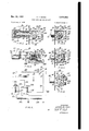
Referring now specifically to Fig. 1, the single embodiment of the ihventionthere represented includes the shift impulse solenoid mechanism 20, consisting of solenoids 20a, 20b and solenoid shaft 2|, which mechanism is adapted to be mounted beneath the floor 22 of a vehicle and for attachment to the conventional transmission lever 23 for changing gears. Also mounted beheath floor 2'2, adjacent the clutch lever 24 and below clutch pedal 25. is the switch 26 which is electrically connected, as indicated, to relays or switch solenoids 21a, 21b for operation of the shift impulse solenoids 20a, 201). It will be Oh"- served that the apparatus of the invention is thus connected to the mechanical and electrical parts of a manually operable vehicle withcut removing or displacing any of the original manual g'ear shifting parts, which include the gear shift handle 3!), gear shift column 3|, sector 32 which is non=rotatably attached to gear shift column 3|, lever arm '33 which is pivotally attached to collar 34, the latter being bolted to sector 32, the crank lever 35 which is pivotally attached at 36 to the frame of the vehicle and at 31 to lever arm 33, and the transmission lever 23 which is pivotal 13' attached at 49 to crank lever 35.
Also unaltered by the attachment are the conventional clutch lever '24 and clutch pedal 25 which serve to actuate the switch 25 when the clutch pedal is depressed and the engine and transmission are out of engagement, as will be apparent. However, the clutch pedal 25 desirably carries a wear block 38 which contacts switch 26 when the clutch pedal 25 is depressed. The details of the clutch mechanism and the transmission are conventional and are not shown.
The solenoid shaft 2| carries a rigid arm 4| which in turn is attached to link arm 42. Link arm 42 is constructed for attachment by means of U-bolt 43 to transmission lever 23, thereby affording means whereby the shift impulse solenoid 20 actuates the movement of the transmission parts to shift gears.
It will be appreciated that the electrical connections appearing in Fig. 1 are merely schematic and are included in Fig. 1 merely in order to indicate the general character of appropriate electric connections, which are discussed in detail hereinafter. Referring more particularly to Figs. 2 and 3 of the drawings, shift impulse solenoid mechanism 20 includes the solenoids 20a, 201) which are enclosed in casing 44 attached to the baseplate 45 by means of screws. In turn, baseplate 45 is provided with apertures 46 for convenience of attachment to the floor of the vehicle.
Each solenoid 20a, 20b consists of a cylinder having a hollow core 41 serving as a guide track for the longitudinal path of reciprocation of solenoid shaft 2|. modating recesses in the ends of casing 44 and are held in position by shoulders 50. Also disposed in the hollow core 41, at each outer end thereof, is a rubber shim or shock-absorber having a central aperture 52 having a diameter of suflicient size to accommodate pilot induction pins 53 of solenoid shafts 2| when the shaft 2| assumes an extreme position adjacent either end of casing 44. Arm 4| also carries shock absorbing pads 54, of rubber or the like, which are adapted to protect arm 4| and the associated mechanism from shock during operation of the solenoid shifting mechanism.
Mounted on base plate 45 is an insulated electric terminal block 55 carrying connecting terminals 56 for the electrical conduits which serve to energize the solenoids 20a, 20b in a manner more fully to be explained hereinafter. Such conduits, together with the electrical conduits directly associated with the solenoids 20a, 29b are represented in Fig. 3.
The casing 44 completely encloses the shift impulse solenoid mechanism from all sides but is provided with a longitudinally extending slotway 51 which accommodates and serves as a guide for the rigid arm 4|.
The switch 26 which is of novel construction and constitutes an important element of the magnetic shifting apparatus, is represented in particular detail in Figs. 4-8. The switch 26 has a flat plate 60 provided with apertures 6| which accommodate bolts or like means for attaching the switch 26 to the floor of the vehicle. Attached to the flat plate 80 is a tube 62 enclosing the spiral spring 63. Slidably fitted over the outer surface of tube 62 is a cap 64 carrying the switch operating arm 65 which is aflixed to cap 64. The spring 63 bears against flat plate 60 and cap 54 thereby urging can 64 toward the The solenoids 20 fit in accomleft as viewed in Fig. 5. The extent of such movement is limited by the projection 66 of switch operating arm 65 which contacts the flat plate 6|].
Switch operating arm 65 has a notch 61 which receives the upstanding lug 10 formed integrally with driving disc 1|. Driving disc 1| is contained in an enclosure 12 having front wall 13, side Walls 14, an end wall 15 and an insulating back wall 16, such enclosure 12 being attached to the flat plate 60 at the side opposite the tube 62. Front wall 13 of enclosure 12 carries a pivot pin 11 about which driving disc 1| is free to rotate. Driving disc 1| has openings which are spaced to receive the inclined studs 8| which constitute an integral part of driven disc 82, the latter being rotatably mounted on pin 11 in face to face relation with driving disc 1|. Referring particularly to Fig. 4, it will be apparent that the studs 8| which are inclined relative to the plane of disc 82 extend into the spaced. openings 89 ofdisc 1| which is partly in section in this figure and have flat lagging edges 83 which contact the lagging edges 84, constituting one boundary of openings 80 in disc 82, when the switch operating arm 55 is moved toward the right from the position it occupies as observed in Fig. 6. The flat surfaces of these edges 83, 84 contact each other thereby transmitting rotary motion from drive disc 1| to driven disc 82. However due to the inclination of the studs 9|, no motion is imparted to the driven disc 82 when the arm 65 is moved toward the left to the position it occupies as observed in Fig. 6, and driving disc 1| rotates relative to driven disc 82. Driven disc 82 carries the projecting lug 85 which engages the slot 85 in contact disc 81 which is also rotatably mounted on pivot pin 11.
Non-rotatably attached to contact disc 81 is the metallic contact piece having a central portion 9| carrying three integrally formed contact clips 92. The contact clips 92 have central depressions 93 suitably shaped to accommodate the electric contacts 94a, 94b, as appears in particular detail in Figs. 4 and '7. The contacts 94a, 941; are stationarily mounted on insulating back wall 15 and are connected electrically to the three terminals 95, 96, 91 as indicated in Fig. 8 of the drawings. Spring 98 urges contact clips 92 toward contacts 94a, 9412.
It will be observed that of the contacts 94a, one is connected to terminal 95, another to terminal 96, and the other is free of connection to any terminal. Similarly of contacts 94b, one contact is connected to terminal 95, another to terminal 91, and the third unconnected. It will be apparent that two different settings of the contact clips 92 relative to the contact elements 94a, 941) may be effected. In accordance with one such setting the terminals 95, 96 are electrically connected, and in accordance with the other setting the terminals 96, 91 are electrically connected in similar manner. Accordingly the movement of switch operating arm 65 to the right as viewed in Fig. 6 breaks the connection between one set of contacts and also establishes connection between the other set of contacts. Return movement of switch operating arm 65, in the opposite direction, does not change the electric connections thus established.
The end wall 15 of switch 26 is apertured at we providing. free space for penetration of the extension arm |0| which is formed integrally with switch operating arm 65. Also mounted on the end wall 15 are the electrically insulated terminals N12,. L03; whicni respectively carry: the, spring metal leaves I04; Hi5;v Thespring metal-leaf IM carries. a block Iii] 6" of electric: insulating material. The block I06? is in alignment with the switch operating. arm 6'? and disposed in the path of advancement of-' extension arm Ill'I' which serves when moved toward the leaf- IM to bend the springImeta-l' leaf IIl i; thereby bringing together the electric contacts. Itl, Ht. Due to their inherent resiliency the spring leaves I84, I05 assume separate positions in which the contacts ilil, III! are open whenthe" extension arm' IGI is withdrawn from block" I706.
Block I86 and extension arm ii I' are spaced apart. at a distance greater than the minimum distance'travelediby switch: operating arm. 65 necessary-for resetting the contact clips 52. Accordingly the contact clips 92' serve as. preselecting means effective to switch. from one electric circuit to: select another" in response to movement of switch. operatingarm 65, and spring metal leaves Iild IE5. may SBIVQWOJ close the selected circuit or another circuit in response to. further movement or. switch.operatingv arm iidinthe same direction.
It will beobservedlthat. cap t i has threads; I l I engaging threads I IZI of adjusting. head I I3. The adjusting head III-3' has an inside diameter slightly less than the outside diameter of cap. (it and is provided with longitudinal slots I Is dividing adjusting head" H3 into four resilient portions and thereby attaining tight fitting contact between the threads IIIZ, II2. Since the clutch pedal 24 or other moving part of the clutch operating mechanism also operates switch 26 by contacting thef free end of adjusting head H3, the gear shifting action may be timed and coordinated with the clutch disengaging action by adjusting the distance between the adjusting head H3 and the clutch operating mechanism. Such adjustment is conveniently attained by turning the adjusting head I 3 relative to cap 64.
Referring now to Fig. 9 of the drawings, wherein one form of wiring diagram for the gear shifting deviceis represented, H5- designates the battery one terminal of which is connected to ground, the other terminal being connected to conductor IIS which supplies current for operating the shift impulse solenoids 26d, Eilb. The battery is connected through conductors I Iii, I I1, resistor G20, and conductor I2I to spring metal leai' it i of switch 25. Spring metal leaf IE5 is connected to terminal st of the selector portion of switch 26, the other terminals thereof being designated 95 and 8?. Terminal 95 is connected through conductor I22 to the magnetic coil of relay or switch solenoid 27a and thence to ground. $imilarly terminal 'I is connected through conductor 5'23 to relay or switch solenoid 2%, and to ground. The circuits including the switch solenoids Zia, 21b are low current auxiliary circuits, which may include the resistor I28 as shown or may include equivalent electric elements serving to decrease the current flow. In practice, the energy for these auxiliary low-current circuits may be obtained by connection to low-current meter terminals on the instrument panel of the vehicle.
Battery H5 is connected through conductors I Iii, I25 to the switch contact [25a of switch solenoid 21a. Contact IZEa is connected by conductor I27 through shift impulse solenoid 28a and thence to ground. When switch solenoid contacts IZEa, I26a are closed, a relatively high current flows through the circuit thus completed. Similar connections, including conductor I30,
contacts. I25i1 andr I261), conductor I3I, solenoid 20b; and? ground connection are provided for energizing shift impulse solenoid 2%.
From; the. foregoing; description the operation of the magnetic gear; shift attachment will. be readily" apparent. Assuming. for purposes of illustration that the attachment is operatively connected as illustrated in Figs. 1 and 9, that switch 26: is initially set for energizing switch solenoid 2 'm',.andithat. the transmission is initially set in: neutralp'osition', the: operator may depress the'clutch pedal: 25 to a point" where adjusting hea'd H 3 of SWilTClTEfi. is contacted by the clutch pedal and resistance due to the action of spring 63 is encountered... In this position the clutch plates are disengaged and. the. gears may be shifted freely by hand. in. the conventional manner; However, further depression of. the clutch pedal by the operator moves the switch operating arm 6.5,th'ere'by rotating the contact clips 92' and shitting switch contacts as previously described to pre'select: the low current circuit including switch solenoid 2119. Still further depression of the clutch pedal brings the contacts It], [It together thereby closing the preselected switch solenoid 27b and energizing. the corresponding shift impulse solenoid 2%.. Immediately the shift impulse solenoid 2.131) moves the link arm as to shift gears into the corresponding position. when th s operator subsequently permits the clutch pedal to rise, the switch elements I81, Iii separate and deenergize the switch solenoid 211) as well as the corresponding shift impulse solenoid 2st. As the clutch. pedal is raised, switch operating arm 65 returns to its original position without changing the setting of the switch contacts as determined by the position of contact clips 92, and the clutch mechanism reestablishes engagement between the engine and transmission to drive the vehicle in the newly selected gear setting.
Thus it will be apparent that complete gear shifting control is available to the operator in that full manual control is attained by limiting the extent ofdepression of the clutch pedal, gears may be preselected for solenoid operation by depressing the clutch pedal slightly farther, and the actual shift in accordance with such preselection is automatically accomplished by depressing the clutch pedal still farther. Frequently it will be desired merely to alternate between two gear ratios in operating an automobile, and this is accomplished by depressing the clutch pedal to the fullest extent, the gears being selected in alternating sequence by reason of the preselecting action of the switch 26.
While there is represented in the drawings a solenoid mechanism including the two solenoids 23a, 202) which move the transmission lever 23 along a straight line for alternate engagement of two different sets of gears, it will be appreciated that any number of such solenoids, suitably arranged with respect to the transmission mechanism, may be incorporated in the attachment for automatic operation to engage and disengage any or all the gear sets of the transmission. Moreover it will be understood that such operation may be fully automatic, the gears being preselected by selective depression of the clutch pedal, or may be semi-automatic with manual operation interposed when desired.
Although I have described my invention by ref erence to one embodiment thereof, it will be apparent to those skilled in the art that changes may be made in the particular form of the solenoids, the circuit selecting and energizing switches, and the circuits associated therewith, including reversals of parts and substitution of equivalent mechanisms, and that certain features of the invention may be used to advantage without the use of other features, all within the spirit of the invention as defined in the appended claims.
Having thus described my invention, I claim:
1. In a motor vehicle, the combination comprising a lever-actuated clutch and transmission, mechanical means manually operable for changing gears in said transmission, automatic transmission operating mechanism in the form of an attachment comprising spaced shift impulse solenoids, a solenoid shaft reciprocable between said shift impulse solenoids, mechanical means for connecting the solenoid shaft to the transmission to change gears, separate solenoid-energizing electric circuits each including one of said solenoids, a circuit-selector switch connected to said solenoid-energizing circuits, said circuitseleotor switch having capacity to select different circuits in accordance with a definite repetitive cycle, changing from one circuit to another each time it is actuated, a switch operator arm having switch actuator means operatively connected to said circuit-selector switch, fixed means on said clutch lever for moving said switch operator arm, said fixed means and switch operator arm being spaced at a definite predetermined distance from one another greater than the distance through which the clutch lever must be depressed to disengage the clutch, the clutch being thereby disengageable independently of said circuitselector switch.
2. In a vehicle having a floor, engine, a transmission, and a clutch mechanism for engaging and disengaging the engine and transmission to permit changing gears, a clutch operating lever reciprocable through said floor and attached to the clutch mechanism, and a clutch pedal for reciprocating said clutch lever, an attachment comprising spaced electromagnets, a shaft reciprocable between said spaced electromagnets, mechanical linkage connecting said shaft to operate said transmission, electric circuits each connected to one of said electromagnets, and a switch common to said electric circuits, said switch being fixed relative to the floor of the vehicle and including a circuit preselector movable through a definite set of positions in a definite order, a switch operating member reciprocable adjacent to and substantially parallel to the reciprocation of the clutch lever and eifective upon said circuit preselector to move it from one of said positions to the next position in said definite order, said switch operating member having an adjusting head mounted on the free end thereof for engagement with the clutch pedal when the clutch pedal is depressed, said head being mounted on said switch operating member with capacity for adjustment toward and away from said floor and accordingly so positioned with respect to the clutch lever that said switch is unaffected by depression of the clutch pedal to an extent sufiicient to disengage the clutch, but is contacted by further depression of the clutch pedal to reset said circuit preselector, and a circuit closing element actuated through said cap and switch operating member to close the preselected circuit in response to still further depression of the clutch lever.
3. In a motor vehicle having a lever-actuated clutch and a transmission, a pair of shift impulse solenoids, a shaft longitudinally reciprocable under the influence of said shift impulse solenoids, mechanical means for connecting said shaft to operate said transmission, separate solenoid-energizing circuits each including one of said solenoids, a normally open switch included in each of said circuits to maintain the solenoids normally deenergized, a circuit selector switch connected to said solenoid-energizing circuits, said circuit selector switch being arranged adjacent the clutch lever with capacity to switch from one of said solenoid-energizing circuits to the other, and thus to preselect circuits in ac cordance with a definite, repetitive cycle, said normally open switch being positioned adjacent the clutch lever, a switch operator arm having a plurality of switch actuator means one operatively connected to said circuit selector switch and the other to said normally open switch, fixed means on said clutch lever for depressing said switch operator arm, said fixed means and switch operator arm being spaced at a definite predetermined distance from one another greater than the distance through which the clutch lever must be depressed to disengage the clutch, the clutch being thereby disengageable independently of said switches, the respective switch actuator means being spaced from one another so that upon further depressing the clutch lever the circuit preselector switch is actuated independently of the normally open switch and upon still further depressing the clutch lever the normally open switch is closed and a shift impulse solenoid thereby energized.
PHILIP M. KOCH.
REFERENCES CITED The following references are of record in the file of this patent:
UNITED STATES PATENTS Number Name Date 1,372,227 Huggins Mar. 22, 1921 2,182,438 Kahn Dec. 5, 1939 2,236,746 Bush Apr. 1, 1941 2,298,782 Bluemle Oct. 13, 1942
Priority Applications (1)
| Application Number | Priority Date | Filing Date | Title |
|---|---|---|---|
| US171639A US2623402A (en) | 1950-07-01 | 1950-07-01 | Gear shifting attachment |
Applications Claiming Priority (1)
| Application Number | Priority Date | Filing Date | Title |
|---|---|---|---|
| US171639A US2623402A (en) | 1950-07-01 | 1950-07-01 | Gear shifting attachment |
Publications (1)
| Publication Number | Publication Date |
|---|---|
| US2623402A true US2623402A (en) | 1952-12-30 |
Family
ID=22624562
Family Applications (1)
| Application Number | Title | Priority Date | Filing Date |
|---|---|---|---|
| US171639A Expired - Lifetime US2623402A (en) | 1950-07-01 | 1950-07-01 | Gear shifting attachment |
Country Status (1)
| Country | Link |
|---|---|
| US (1) | US2623402A (en) |
Cited By (1)
| Publication number | Priority date | Publication date | Assignee | Title |
|---|---|---|---|---|
| US2712244A (en) * | 1953-12-29 | 1955-07-05 | Theodore I Millen | Transmission operating mechanism |
Citations (4)
| Publication number | Priority date | Publication date | Assignee | Title |
|---|---|---|---|---|
| US1372227A (en) * | 1914-03-23 | 1921-03-22 | Automotive Dev Co Inc | Speed-changing transmission for automobiles |
| US2182438A (en) * | 1936-11-27 | 1939-12-05 | Robert L Kahn | Gear shifting mechanism |
| US2236746A (en) * | 1938-05-26 | 1941-04-01 | Eugene S Bush | Electrical speed-change control apparatus |
| US2298782A (en) * | 1940-05-21 | 1942-10-13 | Gen Motors Corp | Dimmer switch |
-
1950
- 1950-07-01 US US171639A patent/US2623402A/en not_active Expired - Lifetime
Patent Citations (4)
| Publication number | Priority date | Publication date | Assignee | Title |
|---|---|---|---|---|
| US1372227A (en) * | 1914-03-23 | 1921-03-22 | Automotive Dev Co Inc | Speed-changing transmission for automobiles |
| US2182438A (en) * | 1936-11-27 | 1939-12-05 | Robert L Kahn | Gear shifting mechanism |
| US2236746A (en) * | 1938-05-26 | 1941-04-01 | Eugene S Bush | Electrical speed-change control apparatus |
| US2298782A (en) * | 1940-05-21 | 1942-10-13 | Gen Motors Corp | Dimmer switch |
Cited By (1)
| Publication number | Priority date | Publication date | Assignee | Title |
|---|---|---|---|---|
| US2712244A (en) * | 1953-12-29 | 1955-07-05 | Theodore I Millen | Transmission operating mechanism |
Similar Documents
| Publication | Publication Date | Title |
|---|---|---|
| US2192714A (en) | Electric throttle control | |
| US2358094A (en) | Switch-over device | |
| US2623402A (en) | Gear shifting attachment | |
| US2244092A (en) | Automatic preselector means to shift gears | |
| US2258747A (en) | Direction signal | |
| US2497930A (en) | Transmission control | |
| US3183314A (en) | Seat adjusting mechanism position responsive switch | |
| US2657287A (en) | Direction signal switch | |
| US2824459A (en) | Transmission control apparatus | |
| US2826929A (en) | Transmission control | |
| US2269970A (en) | Gearshift mechanism | |
| US3023388A (en) | Composite electrical control device for radio receivers | |
| US2217066A (en) | Station preselector | |
| US4133219A (en) | Transmission shift control mechanism | |
| US2214890A (en) | Switch for electric pencil sharpeners | |
| US2220996A (en) | Automatic ratio selector for electrically controlled gear shifting mechanism | |
| US3290955A (en) | Transmission | |
| US3737817A (en) | Push-button operated tuner | |
| US2902881A (en) | Vehicle transmission control apparatus | |
| US2203297A (en) | Control mechanism | |
| US2578158A (en) | Electrical circuit for transmission and clutch control | |
| US3256033A (en) | Seat positioning apparatus | |
| US2215229A (en) | Automobile signal switch | |
| US2252273A (en) | Transmission control mechanism | |
| US3247434A (en) | Electrical control means |