US2612114A - Vane pump or motor - Google Patents
Vane pump or motor Download PDFInfo
- Publication number
- US2612114A US2612114A US19410A US1941048A US2612114A US 2612114 A US2612114 A US 2612114A US 19410 A US19410 A US 19410A US 1941048 A US1941048 A US 1941048A US 2612114 A US2612114 A US 2612114A
- Authority
- US
- United States
- Prior art keywords
- rotor
- pump
- vane
- cylinder
- frame
- Prior art date
- Legal status (The legal status is an assumption and is not a legal conclusion. Google has not performed a legal analysis and makes no representation as to the accuracy of the status listed.)
- Expired - Lifetime
Links
Images


Classifications
-
- F—MECHANICAL ENGINEERING; LIGHTING; HEATING; WEAPONS; BLASTING
- F04—POSITIVE - DISPLACEMENT MACHINES FOR LIQUIDS; PUMPS FOR LIQUIDS OR ELASTIC FLUIDS
- F04C—ROTARY-PISTON, OR OSCILLATING-PISTON, POSITIVE-DISPLACEMENT MACHINES FOR LIQUIDS; ROTARY-PISTON, OR OSCILLATING-PISTON, POSITIVE-DISPLACEMENT PUMPS
- F04C14/00—Control of, monitoring of, or safety arrangements for, machines, pumps or pumping installations
- F04C14/18—Control of, monitoring of, or safety arrangements for, machines, pumps or pumping installations characterised by varying the volume of the working chamber
- F04C14/22—Control of, monitoring of, or safety arrangements for, machines, pumps or pumping installations characterised by varying the volume of the working chamber by changing the eccentricity between cooperating members
- F04C14/223—Control of, monitoring of, or safety arrangements for, machines, pumps or pumping installations characterised by varying the volume of the working chamber by changing the eccentricity between cooperating members using a movable cam
-
- F—MECHANICAL ENGINEERING; LIGHTING; HEATING; WEAPONS; BLASTING
- F01—MACHINES OR ENGINES IN GENERAL; ENGINE PLANTS IN GENERAL; STEAM ENGINES
- F01C—ROTARY-PISTON OR OSCILLATING-PISTON MACHINES OR ENGINES
- F01C21/00—Component parts, details or accessories not provided for in groups F01C1/00 - F01C20/00
- F01C21/08—Rotary pistons
- F01C21/0809—Construction of vanes or vane holders
- F01C21/0818—Vane tracking; control therefor
- F01C21/0854—Vane tracking; control therefor by fluid means
- F01C21/0863—Vane tracking; control therefor by fluid means the fluid being the working fluid
Definitions
- FIG.3 VANE PUMP OR MOTOR Filed April 6,1948 '4 Sheets-Sheet 3 FIG.3
- WALTER ERNST 0 12% mam AT TO RN EVS sgpt. 30, 1952 w. ERNST VANE PUMP OR MOTOR 4 Sheets-Sheet 4 Filed April 6, 1948 INVENTOR WALTER ERNST.
- This invention relates to varied hydraulic apparatus such as vane pumps and' vane motors.
- the particular object of this invention is to provide an improved design of vane pump or motor having improved operating characteristics and which is relatively simple and inexpensive to manufacture.
- Another object is to provide a vane pump or motor so designed that it is adapted for being manufactured in different sizesthereby to provide for different capacities.
- a still further object is the provision of a vane pump or motor in which the unit is adapted for operating in either direction'of rotation and with a fluid flow taking place therethrough in either direction in order that the said pump or motor can be adapted to different situations.
- a still further object isthe provision of a vane pump or motor which has high efficiency and in which wear on the moving parts is reduced to a minimum.
- a still further object is the provision of a vane pump or motor which is variable in delivery and in which the said delivery can be varied in response to a predetermined control pressure.
- Figure 1 is a transverse section through a unit constructed according to this invention and is generally indicated by the line l-l on Figure 2; i
- Figure 2 is a transverse section through the unit as indicated by the line 2--2 on Figure 1 with portions of the unit in elevation;
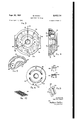
- Figure-3 is a view looking in at the face of the right hand end frame in Figure 2 and is indicated by the line 33 on Figure 2;
- Figure l' is a section through the endframe shown in Figure 3 and as indicated by the line 44-on Figure 3; v
- Figure 5- is a sectional view indicated by the line 5-5 on Figure 4 and showing the arrangement ,of one of the fluid flow pasasges in the end frame;
- Figure 6 is a fragmentary view showing one of the Wear plates which are disposed on each side of the .rotor'of the unit;
- Figures 7; 8 and 9 are views showing one of r the vanes carried by the rotor of the unit
- FIG. 10 is a perspective view showing-oneofj the anti-friction bearings which 1 journal the movable flow controlling member or shift ringof the unit;
- Figure 11 is a somewhat enlarged view show:v ing the arrangement of the vanes in the rotor and the manner in which the passages .in the vanes; cooperate ,to produce high efficiency of operai m' :j.
- Figure 12 is-afragmentary view-showingt means forsupporting the anti-friction bearings; betweenthe shifting ring and the pumprhous-v-z and H Figure 13 is a plan view taken over-on
- the shifting ring 14 is similarly bored as at-ie; to provide for a'cylinder opening within which there is rotatably mounted the rotor t- 7
- On each side of the rotor l8 ther is a brass; Wear plate 20 and it'will be noted thatrwhile therotor and the cylinder block are-of 'exactlyzthe same axial length, the intermediate frame me of the rotor and cylinder block taken together; with the two'wear plates 20.
- f f
- the rotor l8 has hub partsl' extendingvoppoe; sitely from'each'sid'e thereof as'shown at-"30 in Figure 2 andthese "hub parts-are 'journaledtini sleeve bearings 32 which are carried in suitably machined-bores in the end frameun'emberscf xii-"* It Willbe' apparent atthis 'time thatthe rotor I8 is symmetrical about'a transverse plane. pa'ssu ing through its center so that th'e'said rotor can be turned degrees if it is 'desired 'for the said unit to operate in the opposite direction of rota .tion.”
- the rotor I8 is centrallybored receiving pressiorr: spring 68.
- the left hand end frame, and through which the end of the shaft 34 extends, includes a face type sealing arrangement 38 which prevents leakage of fluid from the inside i of the pump casing, I
- the rotor andshaft,areiindepenm' ently journaled the rotor may be said to float" 4 has therein a plunger 12 that bears on the left side of the shifting ring 14 and thus acts in opposition to the thrust of the plunger 58 thereon.
- the plunger 12 is reciprocable in the cylinder bore 14 and the member 10 and connected with the plunger 12 is a rod 16 which extends out the left side of the member 10 and intoan adjustable cap 18 whereinathe'said,rod'hasa head Bothereon.
- the adjustable cap 'IB' is threaded" to the member 10 and is thus adjustable relative thereto,- so that the exact position at which the head 80abut the said cap member can be adjusted.
- the cap member also has therein the adjusting screw. 82 which abuts-the head 80 on its left side and thus-predetermines the maximum left hand position-of the shifting ring [4. The adjusting within the pump housing andgthegonly forces;-
- The-rotor [8- has aplurality of vane receiving. slots:therein as shown. at 42"- and these: slots are unseen thedirection of" rotation of" the rotor; This is done for the purpose of lengthening the support forthe' vanesthus reducing unit stress onthe 'van'esand'the walls of the slots in whichv they-"rest and inducing: longer life" of the unit thereby.
- each of the slots 42 there isavane 44which is-axially of thesame length a's: the rotor and-cylinder blocle and thus fits' closely be tween the-wear platesn;
- each of the-slots 42- preferably terminates at-it's-inner end-in an axialbore 46.
- the plunger 58 has a head 62 thereon within a sleeve member 64 that is bolted-to axsuitably formed pad 65: at that side of;the framemember 1.01
- the sleeve? member 64 is. threaded "andre-i ceiveszia'cap 662and1 between the: said cap andthe: headifik of. thee-plunger 58: there bearsa com.-.
- the' said end'frame member hasa pair; of; ports;
- passages .94 andbfirespectivcly, in the ndiframe-
- These passages aregarcuately; arranged as.- indirr-x cated in- Eigures 3..4, and, 5 and-open:;i nwa1 dly toward therotor-of the unit-., 'l'hewe xp tfifis 20-areg similarly provided; with the; arcuate;slots-,
- each vane similarly, has a slot I04 therein, butthe slot I04 opens at the outer edge of the vane and i's'closed adjacent the-inner edge thereofi 1 the outer edge
- the vane indicated at Ain Figure l'l'the closed ends of the slots I02 and I04 are spaced apart so that asthe closede'n'd of the slot I02 emerges from the periphery of the rotor the closed endof'the slot I04 passes into the vane slot and communication thereofv with the bore'46 is thus interrupted.
- vane B has pressure conducted to the bore 46' at the inner edge thereof from the pressure zone of the pump by means of the groove I04 "out in the trailing side of the'said vane. This maintainsthe vane outwardly during its travel across the lap betweenthe slots 98 and I00 and thereby prevents any leakage of fluid past the vane and which leaka'ge would contribute to ineflicient operation.
- the vane is passing through the suction zone it is relatively immaterial whether it is maintained outwardly against the periphery 'of the cylinder block or not, al-
- the slots I02 and I04 also prevent any trapping of fluid in the bores 46, which trapping of fluid might lead to development of excessive pressures and induce high rates of wear between the ends of the vanes and the cylinder block, or prevent the vanesfrom moving outwardly against the cylinder block.
- the inside of the pump casing be adapted for being drained periodically or for being connected with a slippage pump which will continuously remove fluid therefrom which has leaked from the normal flow passage.
- a drain port IIO all parts of the inside of the pump casing which do not form a portion of the flow passage through the pump are connected/with a drain port IIO.
- a' -vane pump-g a frame,;a boredv cylinder -b1ock; in; s aid fram-emoyablein a: direction trans verselyj of tlj ei-boreyin the ,bloclg; a tvaned rotor eccentrically mounted in the bore;in' ;said-,cy1in der block, a-:- pair; of mounting loads formed on opposite ;sides .-.,of :"said, frame; spring) means mounted-on; one. of-isaid .pads; and-, acting on. said blocktoeur-ge it; imone direction in the.
Landscapes
- Engineering & Computer Science (AREA)
- Mechanical Engineering (AREA)
- General Engineering & Computer Science (AREA)
- Rotary Pumps (AREA)
Description
Sept. 30, 1952 w. ERNST VANE PUMP OR MOTOR 4 Sheets-Sheet 1 Filed April 6, 1948 T s S RN H mm N R m N Av IE A m. W
Y B ND Sept. 30, 1952 w, E T 2,612,114
VANE PUMP OR MOTOR Filed April 6,1948 '4 Sheets-Sheet 3 FIG.3
FlG.- 104 3,777,711 44 INVENTOR.
WALTER ERNST 0 12% mam AT TO RN EVS sgpt. 30, 1952 w. ERNST VANE PUMP OR MOTOR 4 Sheets-Sheet 4 Filed April 6, 1948 INVENTOR WALTER ERNST.
ATTORNEYS f atenteci sept.
assignments, to The Thompson Grinder Com}- pany, Springfield, Ohio, a corporation of Ohio Application April 6, 1948, Serial No. 19,410
fl claims. (01. 103 -120) This invention relates to varied hydraulic apparatus such as vane pumps and' vane motors.
The particular object of this invention is to provide an improved design of vane pump or motor having improved operating characteristics and which is relatively simple and inexpensive to manufacture.
Another object is to provide a vane pump or motor so designed that it is adapted for being manufactured in different sizesthereby to provide for different capacities.
A still further object is the provision of a vane pump or motor in which the unit is adapted for operating in either direction'of rotation and with a fluid flow taking place therethrough in either direction in order that the said pump or motor can be adapted to different situations.
A still further object isthe provision of a vane pump or motor which has high efficiency and in which wear on the moving parts is reduced to a minimum. s
It is also an object of this invention to so arrange a vane pump or motor that the rotor thereof floats within the housing of the unit. thereby eliminating high stresses ordinarily 611001.111! tered in such devices.
A still further object is the provision of a vane pump or motor which is variable in delivery and in which the said delivery can be varied in response to a predetermined control pressure.
These and other objects and advantages will become more apparent upon reference to the following description taken in connection with the accompanying drawings in which:
Figure 1 is a transverse section through a unit constructed according to this invention and is generally indicated by the line l-l on Figure 2; i
Figure 2 is a transverse section through the unit as indicated by the line 2--2 on Figure 1 with portions of the unit in elevation;
Figure-3 is a view looking in at the face of the right hand end frame in Figure 2 and is indicated by the line 33 on Figure 2;
Figure l'is a section through the endframe shown in Figure 3 and as indicated by the line 44-on Figure 3; v
Figure 5- is a sectional view indicated by the line 5-5 on Figure 4 and showing the arrangement ,of one of the fluid flow pasasges in the end frame; I
Figure 6 is a fragmentary view showing one of the Wear plates which are disposed on each side of the .rotor'of the unit;
Figures 7; 8 and 9 are views showing one of r the vanes carried by the rotor of the unit;
the anti-friction bearings and is generally cated by the-line l3--I3 nFigure ,1.
tber 1 Dis equal in axial len h to the axial leng J Figure 10 is a perspective view showing-oneofj the anti-friction bearings which 1 journal the movable flow controlling member or shift ringof the unit; I
Figure 11 is a somewhat enlarged view show:v ing the arrangement of the vanes in the rotor and the manner in which the passages .in the vanes; cooperate ,to produce high efficiency of operai m' :j.
Figure 12 is-afragmentary view-showingt means forsupporting the anti-friction bearings; betweenthe shifting ring and the pumprhous-v-z and H Figure 13 is a plan view taken over-on The shifting ring 14 is similarly bored as at-ie; to provide for a'cylinder opening within which there is rotatably mounted the rotor t- 7 On each side of the rotor l8 ther is a brass; Wear plate 20 and it'will be noted thatrwhile therotor and the cylinder block are-of 'exactlyzthe same axial length, the intermediate frame me of the rotor and cylinder block taken together; with the two'wear plates 20. f f,
on each side of the intermediate-frame mem berlfl is an end frame member, theleft handone of which is indicated at 221iand the right:- hand one of which is indicated -at;-2,4.- ,The'in-; termediate frame member 'and the end; frame members are rigidly clamped togetherby a, -plu. rality of through bolts 26 ,and there are -pref ably the'res'ilient sealing rings :28 which rest between the intermediate frame member :andtheendxframe members. The rotor l8 has hub partsl' extendingvoppoe; sitely from'each'sid'e thereof as'shown at-"30 in Figure 2 andthese "hub parts-are 'journaledtini sleeve bearings 32 which are carried in suitably machined-bores in the end frameun'emberscf xii-"* It Willbe' apparent atthis 'time thatthe rotor I8 is symmetrical about'a transverse plane. pa'ssu ing through its center so that th'e'said rotor can be turned degrees if it is 'desired 'for the said unit to operate in the opposite direction of rota .tion."
The rotor I8 is centrallybored receiving pressiorr: spring 68.
itsfigure-ylspositionsg dependently of the rotor by the antifriction bearings 36, 36, one of which is mounted in each of the end frames. The left hand end frame, and through which the end of the shaft 34 extends, includes a face type sealing arrangement 38 which prevents leakage of fluid from the inside i of the pump casing, I
For effecting a driving connection,;between:- the,
the fact that the rotor andshaft,areiindepenm' ently journaled the rotor may be said to float" 4 has therein a plunger 12 that bears on the left side of the shifting ring 14 and thus acts in opposition to the thrust of the plunger 58 thereon. The plunger 12 is reciprocable in the cylinder bore 14 and the member 10 and connected with the plunger 12 is a rod 16 which extends out the left side of the member 10 and intoan adjustable cap 18 whereinathe'said,rod'hasa head Bothereon. The adjustable cap 'IB'is threaded" to the member 10 and is thus adjustable relative thereto,- so that the exact position at which the head 80abut the said cap member can be adjusted. The cap member also has therein the adjusting screw. 82 which abuts-the head 80 on its left side and thus-predetermines the maximum left hand position-of the shifting ring [4. The adjusting within the pump housing andgthegonly forces;-
transmitted between the shaft and the said rotor are driving torques. This eliminates higl-rpressures of the rotor on the side plate due to slight misaligmnentof; the shaft; andlikewise'lprevents heavy ra'diab loading on the: shaft due to 1 mis-- alignmentof the rotorand; in general; promotes.
long life of the unit by reducing ali wearing. stresses to-the a'bs'olute minimum.
The-rotor [8- has aplurality of vane receiving. slots:therein as shown. at 42"- and these: slots are unseen thedirection of" rotation of" the rotor; This is done for the purpose of lengthening the support forthe' vanesthus reducing unit stress onthe 'van'esand'the walls of the slots in whichv they-"rest and inducing: longer life" of the unit thereby. In each of the slots 42 there isavane 44which is-axially of thesame length a's: the rotor and-cylinder blocle and thus fits' closely be tween the-wear platesn; The outeredgesof the vanes =44 areinc1inedso that they have a substanm1: area of:- contact with theinner periphery of: the cyllnder bloek l 4; For convenience of "marin fafcture. each of the-slots 42- preferably terminates at-it's-inner end-in an axialbore 46.
As mentioned before theunit of this invention 1S1f'V2jIi5b16 in= displacement; To this endthe cylinder block or shifting-ring 14 has 'a-flat' on each side thereof at 48 and opposing'these flats. are the fiat plates 50 which are retained in posi -t mu -mane recess'es=52'-intheintermediate frame member Hlby 1 means of the pilot screws 54..
Between the fiats 48 and theadjacent fiat sur faces off the plates 50 there'are the antiefriction ro'll'enbearings 56. i {The screws 54 and plates 501 areaccurately machinedso that when the said. screws are tightened,'=the-cylinder: block I'4 is retaime'd between the roller bearings; This provide's adequate support for the cylinder block;
butlat the sametime permits: it to be shifted. in;
one direction veryeasily,' At' 'theri'ght side of Figure 1 there is shown a; plunger 58 which-extends through abore 60. m
the=framemember l and bear against the right;
side of the cylinder block [4. The'righte'ndfof: the plunger 58: has a head 62 thereon within a sleeve member 64 that is bolted-to axsuitably formed pad 65: at that side of;the framemember 1.01 The sleeve? member 64 is. threaded "andre-i ceiveszia'cap 662and1 between the: said cap andthe: headifik of. thee-plunger 58: there bearsa com.-.
exerts apnedeterminedbias on;the-;cylinder-block on'shifzting; ring: 14; urgingriti leftwardlx' toward:
;. At the left; .Si'ddiOf: the
This compression, spring pumnzas: illustrated n; Figured; thereqis'fa member 'lflboltedto; a pad-:11; on the frame [0 which is substantially identical; 1 withzthepadid on'which the. sl eve; memberifik 1 .Thezmemben 'Hlis acizl nden bl ifi municatesi with a; passage 88' extending through? the end f-ramecmember24 to alposltioniwhereit will receive pressure. fluid from; one of; the;- flow passages 'in-the'unitu Fluid is .suppliedsto and takenafrom-the unit by; means of flow passages in the end frame' mem ber 24.; These flow-passages; aregbest; seen; in
Figures 3,14, and::5 whereinyitwill;bezseenithiat:
the' said end'frame memberhasa pair; of; ports;
90 and 92 which communicatewithz the; cored;
passages=.94 andbfirespectivcly, in the ndiframe- These passages aregarcuately; arranged as.- indirr-x cated in- Eigures 3..4, and, 5 and-open:;i nwa1 dly toward therotor-of the unit-., 'l'hewe xp tfifis 20-areg similarly provided; with the; arcuate;slots-,,
98 and"!!! which arebest'illustrated;inFigures, 3 and '6. These arcuateslotscoincidfi; 01?. overlap: the arcuate passages. of; the,- end ,frametmem berand are positioned. radially as; will belsfi nt.
in Figures 1 and 2 so that they providegcome'. munication of the spaces between; the: vanes carried by the rotor and the said arcuate pas-g sages As will. be .noted .in- Figure l the upper; of;
the arcuate slots 98az-communicateswith; the;
spaces between the vanes during the-t1time these; spaces: are decreasing in size v and-Sis thus? the outlet passagewhen'the deviceis being usedas; a pump;- Similarly, "the. arcuate. slotxlllll; com-. municates with the. spaces between the vanes during the-timethey are increasing in size and thus forms the inletpassagewhen. the device is operating-as; a pump.- The pas sages tilt-lead ing from the flow passages in the end f-rame 24 to thepads;B5;and- H which mount themembers 64 and '10 are also illustratedin Figure 3; It will be noted that each cr mearcuate;pas sages 94. and 9,6 haveone of, the said passages 88 extending therefrom to each of; thefsaid pads, and 'H. XIn this manner the cylinder...1'14 can; be. placed. in communication. with veithe of; the i pa s es-from herfin tbi f e m l 01 M o e. 011 h assa es 8. item 5, 3, Th'i s valving arrangement-or the vanes is best illustrated irrl 'igur'es 7 through 9 and 11. In these 'figuresit'will'be noted that the leading side ofeach vane hasa groove or slot I02 therein which is-o'pen at'the' inner edge of the'vane and which is closed adjacent thereof.
The trailing side of each vane, similarly, has a slot I04 therein, butthe slot I04 opens at the outer edge of the vane and i's'closed adjacent the-inner edge thereofi 1 the outer edge As will be seen bythe vane indicated at Ain Figure l'l'the closed ends of the slots I02 and I04 are spaced apart so that asthe closede'n'd of the slot I02 emerges from the periphery of the rotor the closed endof'the slot I04 passes into the vane slot and communication thereofv with the bore'46 is thus interrupted. k
- Referring to Figure 11 itwill be noted that the vane at B is approaching the suction zone of the device, assuming that the device is operating'as a pump. Accordingly, vane B has pressure conducted to the bore 46' at the inner edge thereof from the pressure zone of the pump by means of the groove I04 "out in the trailing side of the'said vane. This maintainsthe vane outwardly during its travel across the lap betweenthe slots 98 and I00 and thereby prevents any leakage of fluid past the vane and which leaka'ge would contribute to ineflicient operation. During the time that the vane is passing through the suction zone it is relatively immaterial whether it is maintained outwardly against the periphery 'of the cylinder block or not, al-
though, normally, the centrifugal force acting However, when the vanes reach the position of the vane indicated at C, it again becomes important for the vane to bear against the periphery of the cylinder block. Aswill be noted at this time the vanes have moved outwardly in their slots far enough to establish communication via slots I02 between the space at their leading sides and the bores 46 at their inner edges. conducted down the slots I02 to the bores 46 and urges the vanes outwardly into engagement with the periphery of the cylinder block at least during the time that they are passing across the lap from the suction side of the pump to the pressure side. v It will be observed that, in addition to fulfilling the function of maintaining the vanes insealing engagement with the cylinder block during the passage of the said vanes'across the pump laps, the slots I02 and I04 also prevent any trapping of fluid in the bores 46, which trapping of fluid might lead to development of excessive pressures and induce high rates of wear between the ends of the vanes and the cylinder block, or prevent the vanesfrom moving outwardly against the cylinder block.
Due to the fact that there is always some slight leakage in pressure operated hydraulic devices having sliding fits, it is desirable that the inside of the pump casing be adapted for being drained periodically or for being connected with a slippage pump which will continuously remove fluid therefrom which has leaked from the normal flow passage. To this end all parts of the inside of the pump casing which do not form a portion of the flow passage through the pump are connected/with a drain port IIO. This The pressure ahead of the vanes is thus 6 port is connected by abore I 1'2 with the recess receiving the anti-friction bear'ing36 lnthe cover 24, and is also connected by a-bore 4 with the bottom part of the intermediateframe member I0; In order to provide free drainage of-il-uid to the bore II4 each ofthe wear plates 20 is notched outat its bottom edge as at I I6. By this s arrangement 'all'fluid which leaks into theinside of the pump will be drawn off and "thus prevents a pressure building up within the pump casing which would causeleakage; between the parts thereof or around the shaft 34. The operation of the unit, when operated as a pump, may be described as-follows': i I Referring toFigure 1; the rotorwill operate in a clockwise direction. This willcause fluid to be drawn in through the lower port and to bedischarged from the :upper port inamanner which is well known in'the art; l The pump shifting ring will normally rest in the position shown in Figure l, and which posi-" tion is determined by the adjustment ofthe screw: 82. However, should. the dischargepressureeoi' the pump exceed a predetermined valuepthe:
the eccentricity of the cylindersblock and rotor.
and reduces the pump discharge; Theamountof shifting of the shift ring at that time will be de terminedby the setting of the capla .WhiChiPIO vides an abutment for the head '80.. Usually.- the 1 cap 18 will be positioned to stop the. shifting ring; at about ten percent of the maximum delivery of.
- thepump, this amount of the pump delivery be-.
ing normally necessary for making up slippage.- flAt any time the. discharge pressure of I the pump is relievedafter it has been shifted toward: neutral, the spring 68 will again return theshiftr ing ring to its Figure 1 position and the pump. will resume full delivery. Duringoperation of the pump the vanes, as mentioned before, are urged;
into sealing engagement with the; cylinder block at least during the time the saidvanes are passing I the pump laps and accordingly, a high efficiency,
of operation is obtained. I I
Should it be desired to operate the pumpv in'the: opposite direction of. rotation the rotor is removedg therefrom and reversed and the. pump is then re: assembled. This will cause the vanes to tilt inthe opposite direction and the rotor can then be driven in that direction. I r In order to retain the pressure controlin operation when the direction of rotation of the ,pump is reversedthe member I0 is unbolted-from-the. pad on which it rests and is rotated until the bore 86 therein communicates with the passage 88 extending to the lower of the ports in Figure l, which, at this time, will now be the discharge port. Similarly, if, for some reason, it is desired for the pressure control to be mounted on the right side of the pump as viewed in Figure 1, this, can readily be accomplished by interchangingthe members in and 64 and adjusting the member- 10 so that the bore 86 thereof communicates with; the proper one of the passages 88. I
It will be understood that this invention is. susceptible to modification in order to adapt it tov different usages and conditions and, accordingly, it is desired to comprehend such modificationsv within this invention as may fall within the scopeof the appended claims.
I claim:
1. In a vane pump or motor; a vaned rotor, a cylinder block surroundingsaid rotor eccentric.
thereto and movable in one direction transversely? li ca n n said-trod, awfirst. abutment 'fiedjustabl mounte between sai efid'i'and'isaid p un r adantedl orr ea ine:one-sideorsaid head a d a scc ndrahutment adiusta lyvm untedaonzsai first abutment adaptediforiengaging the 1 other si e; qfzsaid headz-wherebyizrsaid head is; movable between saidmbutments' to-;.provide ;for "spaced stormed nosi iQns:of.; said cylinder tblock.
2::- in. a-:.vaneapump:or motor; aiframerra .ivaned rotor: in; said; frame, a :cylinder :block: surroun nsasaid rotor in-the'frame eccentric: to the. rotor and movable in one;directionin,the frame transversel-y of-,a ;the-rotor for-raincreasingzthe eccentricity, between :.the block and: rotor and; in the opposit direction .fordecreasing the saideccene tricity, a springnin :the l frame at .one; sidejacting ontsaidoblock'to urge itin saidone direction-,,a cylinder on the :other side of said; frame, @a vfluid operable ,plungeriin' the cylinder acting on'said blockdor urging it in 4 the'zother direction, a rod connected toea'nd extending from the :plunger out; the endiof the cylinder opposite-said .p'block, ahead on: the outersenduof the'rod, a capmember threaded toesaid cylinder and having a'shouldered iboresthrough which said :rod extends; said bore beingofv a size to-receive saidrod but smaller than'ithehea'd onthe end of: the rod-,and a-nstop screw athreadediintozsaid'bore, whereby the shoulder ingqthe'boresis engageablewi-thone sidezofzsaid head and v the stop screw: is engageable with; the other-iosidetxthereof' :to predetermine' limits of movement of :said rodand plungerand; therefore,
ofvsai'd block. 7
' 3. :Ima vanepump or motorya frame, a bored cylinder bloclc in-said =frame movable in a directiontransverselyof the bore in the block, a vaned rotor :eccentrically mounted in the "'bore in'said cylinder'block, ports in saidvframercommunicating with the space betweensaid rotoran'd cylinder- =b1ock,- mounting pads formed on opposite sidesof said -frame, a plurality of channels 1. in said frame Ieadingfrom-said ports to spaced points on the-surfacesof said-pads, said points means -acting=onsaid block to-urge it :in-one di- 5o rection, a cylinder mounted-on the other pad, a
plunger.. in the cylinderengaging- "the I cylinder said pad.
tartan mechani-a ass eewameathec ind meeefi ing the interioapflsaid cylindermith apointon the? surface thereof. that ,engagess the? pad, esaid p i t -be naoet-e radia s a c 'o m axis ft e cy nder u hihttit-Mill 'eeiste w h n se1ected.: one of-zther said points on the surface of Y4;. In a' -vane pump-g a frame,;a boredv cylinder -b1ock; in; s aid fram-emoyablein a: direction trans verselyj of tlj ei-boreyin the ,bloclg; a tvaned rotor eccentrically mounted in the bore;in' ;said-,cy1in der block, a-:- pair; of mounting loads formed on opposite ;sides .-.,of :"said, frame; spring) means mounted-on; one. of-isaid .pads; and-, acting on. said blocktoeur-ge it; imone direction in the. lframe a fluid-,operable-- mea 1 1s;-.adapted for acting on} said blockfto .move it. in rthe other;;,direction, -and 1ncluding a cylinder, mountedon v said other: of -.said pads, said cylinder having a channel .Lleading from the-interior: thereofi-fito the-surface of, the cylinder abutting the. said pad, inlet; and ,outlet passageways in said :frame leading t thespace between said rotort-andicylinderl block anduchan nel means inrthe frame connecting each; of said passageways with respectivelyidifierent .points on the surfaces, of 1 each .ofsaid ,pads, said tndints being. so located I that j said fluid operablenmelans can,vbe .mounted on either ,of saidapadsendrbe adjusted thereon to a cause the} said channellin the c-y1inder, .to communicate with any selected one-.of said channel, means; zthelsaid. one padrhavmg a-membertmountedtthereonsclosing thewends y of the Lchannel means ,terminating .thereon and. enclosingisaidspring means. V
1 y I V ;WALTERERNST.
,QREEERE NCE SQCITED FF-he following references are; of arecord innthe fileioft-this patent: v v UNITED STATES PATENTS Number Name JDate w1,035,4 i9 Kinney .Aug. 43,1912 1,240,211. Horyath Sept...18,'191.7 1,943,929 V Rayburn Jan. 16, 193d. 2,141,170 r cCente'rya11 DecI 27,'..-I933 2,149,337 .v Deming l-. Mar, 7,1939 2,215,053 2 .Sta1ey, qs.e t; 24, 119Ao 2A,23 8.;0f62 ,Kendrick .Apr. 15; ,1941 2,256,459 1 .Kendrick Sept. '16, 1941' 2313;0'15 -Kendrick ,et a1. iMar. '9, 19.43 2313256 4 Kendricketal Mar 9,1943 368,223 Kendrick Jan 30,1945 2,420,155 v Tucker (May 76;: 1947 2,423,271 .Talbot .,i lJu1y;1,..1947 2,423,654 A.Le s.-; 1.1 1 ;8,.,;1947
Priority Applications (2)
| Application Number | Priority Date | Filing Date | Title |
|---|---|---|---|
| US19410A US2612114A (en) | 1948-04-06 | 1948-04-06 | Vane pump or motor |
| US106545A US2612115A (en) | 1948-04-06 | 1949-07-25 | Vane pump and vane therefor |
Applications Claiming Priority (1)
| Application Number | Priority Date | Filing Date | Title |
|---|---|---|---|
| US19410A US2612114A (en) | 1948-04-06 | 1948-04-06 | Vane pump or motor |
Publications (1)
| Publication Number | Publication Date |
|---|---|
| US2612114A true US2612114A (en) | 1952-09-30 |
Family
ID=21793055
Family Applications (1)
| Application Number | Title | Priority Date | Filing Date |
|---|---|---|---|
| US19410A Expired - Lifetime US2612114A (en) | 1948-04-06 | 1948-04-06 | Vane pump or motor |
Country Status (1)
| Country | Link |
|---|---|
| US (1) | US2612114A (en) |
Cited By (38)
| Publication number | Priority date | Publication date | Assignee | Title |
|---|---|---|---|---|
| US2754765A (en) * | 1949-01-29 | 1956-07-17 | Joy Mfg Co | Variable displacement pump |
| US2768585A (en) * | 1952-12-18 | 1956-10-30 | Schwitzer Corp | Pump control mechanism |
| US2787959A (en) * | 1952-05-10 | 1957-04-09 | Vickers Inc | Power transmission |
| US2853022A (en) * | 1955-06-17 | 1958-09-23 | Ernest E Wagner | Control means for positive displacement rotary pumps and hydraulic motors |
| US2883937A (en) * | 1955-01-10 | 1959-04-28 | Borg Warner | Constant pressure variable displacement pump |
| US2885960A (en) * | 1955-11-29 | 1959-05-12 | Hydroaire Inc | High pressure variable delivery rotary vane pump |
| US2922376A (en) * | 1956-09-07 | 1960-01-26 | Tokheim Corp | Variable capacity pump |
| US2929329A (en) * | 1956-12-06 | 1960-03-22 | Gen Motors Corp | Constant pressure variable displacement pump |
| US2955542A (en) * | 1959-09-23 | 1960-10-11 | Gen Motors Corp | Vane pump |
| US2961969A (en) * | 1958-12-09 | 1960-11-29 | Plenty And Son Ltd | Pump |
| US2968251A (en) * | 1953-07-15 | 1961-01-17 | Eaton Mfg Co | Internal gear pump |
| US2969646A (en) * | 1957-01-11 | 1961-01-31 | Racine Hydraulics & Machinery | Variable volume pump hydraulic transmission |
| US2975716A (en) * | 1954-02-03 | 1961-03-21 | Eickmann Karl | Rotary engine, in particular fluid transmission |
| US2981371A (en) * | 1955-04-28 | 1961-04-25 | Gen Motors Corp | Combined variable displacement pumping mechanism |
| US2985109A (en) * | 1955-02-02 | 1961-05-23 | Thompson Grinder Co | Hydraulic pump |
| US3014431A (en) * | 1958-08-15 | 1961-12-26 | Shell Oil Co | Sliding vane pump |
| US3015212A (en) * | 1957-06-26 | 1962-01-02 | Thompson Grinder Co | Pump control |
| US3086475A (en) * | 1963-04-23 | rosa en | ||
| DE1153585B (en) * | 1958-10-04 | 1963-08-29 | Thompson Grinder Company | Device for regulating hydraulic drives, especially for grinding machines, by radial displacement of a ring surrounding the rotor of the pump |
| US3107628A (en) * | 1959-04-15 | 1963-10-22 | Racine Hydraulics & Machinery | Vane type pump |
| US3117529A (en) * | 1960-01-23 | 1964-01-14 | Council Scient Ind Res | Swash plate pumps and motors |
| US3134334A (en) * | 1959-02-10 | 1964-05-26 | Fluid Power Products Inc | Reversible discharge flow variable displacement pump |
| US3162137A (en) * | 1958-12-08 | 1964-12-22 | James F Carner | Variable flow and reversible hydraulic pump |
| US3182641A (en) * | 1961-02-01 | 1965-05-11 | Daimler Benz Ag | Rotary piston engine |
| DE1203611B (en) * | 1957-04-15 | 1965-10-21 | Brakeshoe Internat S A | Adjustable rotary lobe pump with three rotors |
| US3465682A (en) * | 1967-10-26 | 1969-09-09 | Koehring Co | Variable volume pump |
| US3523746A (en) * | 1968-10-31 | 1970-08-11 | Racine Hydraulics Inc | Fluid translating device |
| US4392795A (en) * | 1981-01-30 | 1983-07-12 | Rexnord Inc. | Wear resistant rotor slots for vane-type pumps or motors |
| US4780069A (en) * | 1984-08-14 | 1988-10-25 | Mannesmann Rexroth Gmbh | Directlly actuated vane-type pump |
| US5435698A (en) * | 1993-07-29 | 1995-07-25 | Techco Corporation | Bootstrap power steering systems |
| US5618165A (en) * | 1992-04-14 | 1997-04-08 | Ab Volvo | Variable displacement and constant pressure pump |
| FR2862354A1 (en) * | 2003-11-13 | 2005-05-20 | Daimler Chrysler Ag | Variable displacement pump e.g. vane pump, for internal combustion engine, has nesting ring moved transversally with respect to rotor in chamber which has sealing units acting on rings flat wheels supported on surface of chamber |
| WO2008065513A3 (en) * | 2006-11-29 | 2008-10-30 | Pierburg Spa | A variable-displacement vane oil pump |
| US20100237034A1 (en) * | 2009-03-17 | 2010-09-23 | Theodosios Kountotsis | Multi-chambered bottles for separating contents and methods of manufacturing the same |
| US20100296956A1 (en) * | 2009-05-20 | 2010-11-25 | Hoehn Richard T | Variable displacement pumps and vane pump control systems |
| US20110194962A1 (en) * | 2008-10-09 | 2011-08-11 | Kyung Yul Hyun | Vane pump with variable discharge volume |
| DE102014221791A1 (en) * | 2014-10-27 | 2016-04-28 | Robert Bosch Gmbh | Hydrostatic positive displacement machine |
| US20180003278A1 (en) * | 2015-01-13 | 2018-01-04 | Gino MINICHIELLO | Hydraulic torque converter |
Citations (15)
| Publication number | Priority date | Publication date | Assignee | Title |
|---|---|---|---|---|
| US1035449A (en) * | 1912-01-12 | 1912-08-13 | Justus R Kinney | Rotary pump for reversing-engines. |
| US1240211A (en) * | 1916-01-22 | 1917-09-18 | Geza Horvath | Pump. |
| US1943929A (en) * | 1929-07-23 | 1934-01-16 | Automotive Engineering Corp | Rotary hydraulic power transmission |
| US2141170A (en) * | 1934-04-13 | 1938-12-27 | Manly Corp | Rotary pump or motor |
| US2149337A (en) * | 1934-12-11 | 1939-03-07 | Deming Rotary Pump Company | Rotary pump |
| US2216053A (en) * | 1939-01-24 | 1940-09-24 | Nat Transit Pump & Machine Co | Rotary pump of the single rotor type |
| US2238062A (en) * | 1939-01-14 | 1941-04-15 | Manly Corp | Variable capacity pump and control therefor |
| US2256459A (en) * | 1941-02-12 | 1941-09-16 | Manly Corp | Fluid pressure device |
| US2313075A (en) * | 1939-03-23 | 1943-03-09 | Manly Corp | Fluid pressure device |
| US2313246A (en) * | 1941-05-31 | 1943-03-09 | Manly Corp | Fluid pressure device |
| US2368223A (en) * | 1940-11-23 | 1945-01-30 | Manly Corp | Fluid pressure device |
| US2420155A (en) * | 1941-05-31 | 1947-05-06 | Hydraulic Dev Corp Inc | Control mechanism for hydraulic transmissions |
| US2423271A (en) * | 1942-09-11 | 1947-07-01 | Frank A Talbot | Rotary motor, pump, and the like |
| US2423654A (en) * | 1944-08-03 | 1947-07-08 | Arthur F Leis | Variable delivery vane pump |
| US2426361A (en) * | 1942-12-09 | 1947-08-26 | Lester Engineering Co | Variable delivery alternating piston pump |
-
1948
- 1948-04-06 US US19410A patent/US2612114A/en not_active Expired - Lifetime
Patent Citations (15)
| Publication number | Priority date | Publication date | Assignee | Title |
|---|---|---|---|---|
| US1035449A (en) * | 1912-01-12 | 1912-08-13 | Justus R Kinney | Rotary pump for reversing-engines. |
| US1240211A (en) * | 1916-01-22 | 1917-09-18 | Geza Horvath | Pump. |
| US1943929A (en) * | 1929-07-23 | 1934-01-16 | Automotive Engineering Corp | Rotary hydraulic power transmission |
| US2141170A (en) * | 1934-04-13 | 1938-12-27 | Manly Corp | Rotary pump or motor |
| US2149337A (en) * | 1934-12-11 | 1939-03-07 | Deming Rotary Pump Company | Rotary pump |
| US2238062A (en) * | 1939-01-14 | 1941-04-15 | Manly Corp | Variable capacity pump and control therefor |
| US2216053A (en) * | 1939-01-24 | 1940-09-24 | Nat Transit Pump & Machine Co | Rotary pump of the single rotor type |
| US2313075A (en) * | 1939-03-23 | 1943-03-09 | Manly Corp | Fluid pressure device |
| US2368223A (en) * | 1940-11-23 | 1945-01-30 | Manly Corp | Fluid pressure device |
| US2256459A (en) * | 1941-02-12 | 1941-09-16 | Manly Corp | Fluid pressure device |
| US2313246A (en) * | 1941-05-31 | 1943-03-09 | Manly Corp | Fluid pressure device |
| US2420155A (en) * | 1941-05-31 | 1947-05-06 | Hydraulic Dev Corp Inc | Control mechanism for hydraulic transmissions |
| US2423271A (en) * | 1942-09-11 | 1947-07-01 | Frank A Talbot | Rotary motor, pump, and the like |
| US2426361A (en) * | 1942-12-09 | 1947-08-26 | Lester Engineering Co | Variable delivery alternating piston pump |
| US2423654A (en) * | 1944-08-03 | 1947-07-08 | Arthur F Leis | Variable delivery vane pump |
Cited By (41)
| Publication number | Priority date | Publication date | Assignee | Title |
|---|---|---|---|---|
| US3086475A (en) * | 1963-04-23 | rosa en | ||
| US2754765A (en) * | 1949-01-29 | 1956-07-17 | Joy Mfg Co | Variable displacement pump |
| US2787959A (en) * | 1952-05-10 | 1957-04-09 | Vickers Inc | Power transmission |
| US2768585A (en) * | 1952-12-18 | 1956-10-30 | Schwitzer Corp | Pump control mechanism |
| US2968251A (en) * | 1953-07-15 | 1961-01-17 | Eaton Mfg Co | Internal gear pump |
| US2975716A (en) * | 1954-02-03 | 1961-03-21 | Eickmann Karl | Rotary engine, in particular fluid transmission |
| US2883937A (en) * | 1955-01-10 | 1959-04-28 | Borg Warner | Constant pressure variable displacement pump |
| US2985109A (en) * | 1955-02-02 | 1961-05-23 | Thompson Grinder Co | Hydraulic pump |
| US2981371A (en) * | 1955-04-28 | 1961-04-25 | Gen Motors Corp | Combined variable displacement pumping mechanism |
| US2853022A (en) * | 1955-06-17 | 1958-09-23 | Ernest E Wagner | Control means for positive displacement rotary pumps and hydraulic motors |
| US2885960A (en) * | 1955-11-29 | 1959-05-12 | Hydroaire Inc | High pressure variable delivery rotary vane pump |
| US2922376A (en) * | 1956-09-07 | 1960-01-26 | Tokheim Corp | Variable capacity pump |
| US2929329A (en) * | 1956-12-06 | 1960-03-22 | Gen Motors Corp | Constant pressure variable displacement pump |
| US2969646A (en) * | 1957-01-11 | 1961-01-31 | Racine Hydraulics & Machinery | Variable volume pump hydraulic transmission |
| DE1203611B (en) * | 1957-04-15 | 1965-10-21 | Brakeshoe Internat S A | Adjustable rotary lobe pump with three rotors |
| US3015212A (en) * | 1957-06-26 | 1962-01-02 | Thompson Grinder Co | Pump control |
| US3014431A (en) * | 1958-08-15 | 1961-12-26 | Shell Oil Co | Sliding vane pump |
| DE1153585B (en) * | 1958-10-04 | 1963-08-29 | Thompson Grinder Company | Device for regulating hydraulic drives, especially for grinding machines, by radial displacement of a ring surrounding the rotor of the pump |
| US3162137A (en) * | 1958-12-08 | 1964-12-22 | James F Carner | Variable flow and reversible hydraulic pump |
| US2961969A (en) * | 1958-12-09 | 1960-11-29 | Plenty And Son Ltd | Pump |
| US3134334A (en) * | 1959-02-10 | 1964-05-26 | Fluid Power Products Inc | Reversible discharge flow variable displacement pump |
| US3107628A (en) * | 1959-04-15 | 1963-10-22 | Racine Hydraulics & Machinery | Vane type pump |
| US2955542A (en) * | 1959-09-23 | 1960-10-11 | Gen Motors Corp | Vane pump |
| US3117529A (en) * | 1960-01-23 | 1964-01-14 | Council Scient Ind Res | Swash plate pumps and motors |
| US3182641A (en) * | 1961-02-01 | 1965-05-11 | Daimler Benz Ag | Rotary piston engine |
| US3465682A (en) * | 1967-10-26 | 1969-09-09 | Koehring Co | Variable volume pump |
| US3523746A (en) * | 1968-10-31 | 1970-08-11 | Racine Hydraulics Inc | Fluid translating device |
| US4392795A (en) * | 1981-01-30 | 1983-07-12 | Rexnord Inc. | Wear resistant rotor slots for vane-type pumps or motors |
| US4780069A (en) * | 1984-08-14 | 1988-10-25 | Mannesmann Rexroth Gmbh | Directlly actuated vane-type pump |
| US5618165A (en) * | 1992-04-14 | 1997-04-08 | Ab Volvo | Variable displacement and constant pressure pump |
| US5435698A (en) * | 1993-07-29 | 1995-07-25 | Techco Corporation | Bootstrap power steering systems |
| FR2862354A1 (en) * | 2003-11-13 | 2005-05-20 | Daimler Chrysler Ag | Variable displacement pump e.g. vane pump, for internal combustion engine, has nesting ring moved transversally with respect to rotor in chamber which has sealing units acting on rings flat wheels supported on surface of chamber |
| WO2008065513A3 (en) * | 2006-11-29 | 2008-10-30 | Pierburg Spa | A variable-displacement vane oil pump |
| US8469683B2 (en) | 2006-11-29 | 2013-06-25 | Pierburg Pump Technology Italy S.P.A. | Variable-displacement vane oil pump |
| US20110194962A1 (en) * | 2008-10-09 | 2011-08-11 | Kyung Yul Hyun | Vane pump with variable discharge volume |
| US20100237034A1 (en) * | 2009-03-17 | 2010-09-23 | Theodosios Kountotsis | Multi-chambered bottles for separating contents and methods of manufacturing the same |
| US8746475B2 (en) * | 2009-03-17 | 2014-06-10 | Theodosios Kountotsis | Multi-chambered bottles for separating contents and methods of manufacturing the same |
| US20100296956A1 (en) * | 2009-05-20 | 2010-11-25 | Hoehn Richard T | Variable displacement pumps and vane pump control systems |
| DE102014221791A1 (en) * | 2014-10-27 | 2016-04-28 | Robert Bosch Gmbh | Hydrostatic positive displacement machine |
| US20180003278A1 (en) * | 2015-01-13 | 2018-01-04 | Gino MINICHIELLO | Hydraulic torque converter |
| US10626971B2 (en) * | 2015-01-13 | 2020-04-21 | Gino MINICHIELLO | Hydraulic torque converter |
Similar Documents
| Publication | Publication Date | Title |
|---|---|---|
| US2612114A (en) | Vane pump or motor | |
| US3223044A (en) | Three-area vane type fluid pressure energy translating devices | |
| US2255785A (en) | Fluid pressure device | |
| US2646754A (en) | Hydraulic fluid mechanism | |
| US2967488A (en) | Power transmission | |
| US2832293A (en) | Vane pump | |
| US3103893A (en) | Variable displacement engine | |
| US1749121A (en) | Rotary pump | |
| US2278131A (en) | Pump | |
| US2919651A (en) | Power transmission | |
| US2649739A (en) | Constant pressure variable displacement pump | |
| US2962972A (en) | Power transmission | |
| US2809593A (en) | Power transmission | |
| US2955542A (en) | Vane pump | |
| US1190139A (en) | Power-transmitter. | |
| US2962973A (en) | Power transmission | |
| US3011449A (en) | Vaned hydraulic unit | |
| US2164888A (en) | Variable delivery pump | |
| US1819689A (en) | Hydraulic pump | |
| US2827857A (en) | Rotary pump | |
| US2766693A (en) | Pump | |
| US2884865A (en) | Power transmission | |
| US2696787A (en) | Rotary pump | |
| US3761206A (en) | Fluid device | |
| US2967489A (en) | Power transmission |