US2580452A - Automatic control system for aircraft retractable landing gear - Google Patents
Automatic control system for aircraft retractable landing gear Download PDFInfo
- Publication number
- US2580452A US2580452A US48546A US4854648A US2580452A US 2580452 A US2580452 A US 2580452A US 48546 A US48546 A US 48546A US 4854648 A US4854648 A US 4854648A US 2580452 A US2580452 A US 2580452A
- Authority
- US
- United States
- Prior art keywords
- aircraft
- landing gear
- switch
- contacts
- automatic control
- Prior art date
- Legal status (The legal status is an assumption and is not a legal conclusion. Google has not performed a legal analysis and makes no representation as to the accuracy of the status listed.)
- Expired - Lifetime
Links
- QSHDDOUJBYECFT-UHFFFAOYSA-N mercury Chemical compound [Hg] QSHDDOUJBYECFT-UHFFFAOYSA-N 0.000 description 9
- 229910052753 mercury Inorganic materials 0.000 description 9
- 210000001331 nose Anatomy 0.000 description 5
- 230000002441 reversible effect Effects 0.000 description 4
- 230000009194 climbing Effects 0.000 description 2
- 230000008030 elimination Effects 0.000 description 2
- 238000003379 elimination reaction Methods 0.000 description 2
- 239000011521 glass Substances 0.000 description 2
- 238000013459 approach Methods 0.000 description 1
- 230000008602 contraction Effects 0.000 description 1
- 230000003247 decreasing effect Effects 0.000 description 1
- 238000010586 diagram Methods 0.000 description 1
- 238000000034 method Methods 0.000 description 1
- 238000012986 modification Methods 0.000 description 1
- 230000004048 modification Effects 0.000 description 1
- 230000003068 static effect Effects 0.000 description 1
Images
Classifications
-
- B—PERFORMING OPERATIONS; TRANSPORTING
- B64—AIRCRAFT; AVIATION; COSMONAUTICS
- B64C—AEROPLANES; HELICOPTERS
- B64C25/00—Alighting gear
- B64C25/02—Undercarriages
- B64C25/08—Undercarriages non-fixed, e.g. jettisonable
- B64C25/10—Undercarriages non-fixed, e.g. jettisonable retractable, foldable, or the like
- B64C25/18—Operating mechanisms
- B64C25/24—Operating mechanisms electric
Definitions
- the present invention relates to an automatic control system for aircraft retractable landing gear and more particularly to an automatic control system for raising after take-off, and lowering prior to landing, aircraft retractable landing gear.
- this invention comprises an automatic device mounted in the aircraft and arranged to control the actuating source for raising and lowering the aircraft landing gear.
- the device comprises motive means, means operable by said motive means for controlling the actuating source, relay means for actuating said motive means, and switch means responsive to the speed and the inclination of the aircraft for controlling the operation of said relay means.
- the pilot proceeds to prepare for landing by reducing the power and setting the craft in its angle of descent.
- the switch means operates the motive means which causes the landing gear to be lowered.
- the air speed and the angle of climb actuate the motive means in a reverse direction causing the landing gear to rise.
- An object of the present invention is to provide an automatic control system for aircraft retractable landing gear which is responsive to the flight conditions of the craft.
- Another object is the provision of an aircraft automatic control system responsive to the inclination and the air speed of the craft.
- a further object of the invention is the provision of automatic control means for an aircraft for lowering the landing gear of the craft prior to landing and for raising the gear after take-off.
- a still further object is to provide automatic .j i
- control means for an aircraft for lowering the landing gear of the craft when the air speed reaches a predetermined minimum value and the inclination of the craft attains a predetermined angle of negative pitch.
- a final object of the present invention is the provision of automatic control means for raising the landing gear of an aircraft when the air speed attains a, predetermined maximum value and the inclination of the craft reaches a predetermined degree in another direction.
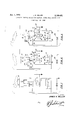
- Fig. l illustrates a side elevation of an aircraft showing the system of the present invention mounted thereon.
- Fig. 2 is a schematic diagram of the system of Fig. 1 illustrating the position of the various elements of the system when the aircraft is climbing after take-olf and the landing gear is in the process of retracting.
- Fig. 3 is a view similar to Fig. 2 showing the elements in landing position.
- FIG. l an aircraft I I having landing gear I'2 and the automatic control system I3 mounted thereon.
- the system I3 may be directly connected to the landing gear I2, or, preferably, may be connected to the actuating source (not shown) for the landing gear and positioned so as to control the operation of the source, and thereby the operation of the landing gear.
- the system I3, as shown in Fig. 2, comprises a landing gear position selector I4 connected to the actuating source (not shown) and operable by an electric motor I5, preferably of the reversible type.
- the motor is preferably provided with limit stops in its extreme forward and reverse positions wherein the landing gear is either fully retracted or extended.
- Motor I5 is controlled by an electromagnetic relay I6 having a coil Il and an armature I8,
- Relay I5 has four fixed contacts, interconnected in pairs, one of each pair being connected to motor I5 by means of leads 22 and 23, respectively, thereby forming a reversing switch for motor I5.
- Armature I8 is normally biased to the upper position, as shown in Fig. 3, whereby electrical connection is made to the motor in such manner as to maintain the landing gear I2 in extended position. It is to be understood that the specific switch connections are merely shown as illustrative and that any other reversing type connection may be used.
- Coil I1 or relay I6 has one of its ends connected to one end of a power supply, such as a battery 24, through limiting resistor 25, and to one contact 25 of an inclinometer switch 21.
- Battery 24 has its other end grounded and has its one end connected yto two other contacts 28, 29 of switch 21, the fourth contact 3i of switch 21 being connected to one of the xed contacts 32 of air speed switch 33.
- Inclinometer switch 21 preferably consists of a glass tube 34 with a small 'amount of mercury 35 contained therein, the mercury ./-electrically connecting the adjacent contacts when it .is in either of its extreme positions. "The travel of mercury 35 within tube 311. is governed by the off-level position of the tube having .its ends angularly spaced preferably approximately "five degrees from the thrust ⁇ line iof .the'f-aircraft.
- Air speed switch 33 has a second fixed contact 36 connected to ground and 'also connected to the other end of 4'coil I1 through a limiting resistor 31, while the movable contact 33 of switch 33 is 'connected to the other end of coil I1.
- Air speed switch 33 'further comprises an air tight case I59 vented tothe airspeed Venturi tube (static), not shown, the case 33 containing a sensi-tive bellows 4I joined to the air speed Pitot tube (pressure), ⁇ not shownfa'nd to a main shaft 42 Lto which thelmovablecontact 38A is connected. All :of the contacts of switch 33 are within case 39, movement of contact 38 being controlled by the yexpansion and contraction Vof bellows di.
- Contacts 32 and 3G are adjustable, onefbeing preferably set in ⁇ a kposition which corresponds to asafemargin 4above stalling speed while 'the other is preferably fixed to Vvcorrespond with va safe margin above -fiying speed.
- Therinvention'described herein may be manufactured and used by or for the Government of the 4United States ⁇ of America for Egovernmental purposes without the payment of ⁇ any royalties -thereon or therefor.
- an yautomatic control system comprising moti-ve means, means operable by said motive means for controlling the operation of said source, Vrelaymeans foractuating saidmotive means,land 'switch means responsive to the .speediand the 1nfclination of the aircraft for controlling the venergization of said relaymeans 2.
- an automatic control system comprising mo- ;tivemeans, selector means operable bysaid motive means for controlling the position of said gear, a ⁇ source of energy for said motive means, .relay means connected .between said source ⁇ and-said motive means for controlling the operation of said motive means, and switch means responsive tothe speed and the vinclination of the aircraft for controlling Vthe energization of said relay means.
- retractable landng fgear In an aircraft, in combination, retractable landng fgear, motive means jfor controlling 'the position of saidlanding gear, a source of energy for 'said 'motive means, relay means for controlling the energy supplied by said'source to said motive means, and switch means responsive to the speed and the inclination of the aircraft for controlling the energization of said relay means.
- said switch means comprises an inclinometer switch responsive to the vinclination of said aircraft and an air speed switch :responsive to the speed of said aircraft.
- Yan automatic icontrol ysystem icomprising motivemeans for controlling'the position of .said landing gear, afsourcevof energy, .relay .means 'for controlling the energy supplied by said sourcel to said motive means, and 'switch means -for controlling the .energization of said relay means,s ⁇ aid switch means comprising an inclinometer switch responsive Sto the inclination of said aircraft and an iair :speed "switch responsive to the speed of said aircraft.
- V6 In a system for automatically controllingthe operation of aircraft retractable landing gear, the combination comprising reversible motive Ameans foricontrolling the ⁇ position of said gear, a source ofelectrical energy, relaymeans for controlling thedirection of energization of said motive means from said source, a first switch responsiveto the inclination of the aircraft for controlling the en ergization of said relay means, and a second switch responsive to the airspeed of the aircraft for controlling the energization of said relay means, said switches being so arranged that actuation of either of them is insufiicient to energize said relay means but is suicient to maintain said relay means energized.
- a source of electrical energy having a coil energizable from said source for controlling the position of said gear, an inclinometer switch having a plurality of pairs of normally open contacts, one of each of said pairs being connected to one terminal of said source, and an airspeed switch having a movable contact responsive to airspeed and connected to one end of said coil and a pair of fixed contacts connected to the other terminal of said source and to the other of one of said pairs of contacts respectively, the other of another of said pairs of contacts being connected to the other terminal of said coil.
- said inclinometer switch has two pairs of normally open contacts arranged so that one of said two pairs of contacts closes when the aircraft is downwardly inclined beyond a predetermined angle and the other of said two pairs of contacts closes when the aircraft is upwardly inclined beyond a predetermined angle.
Landscapes
- Engineering & Computer Science (AREA)
- Mechanical Engineering (AREA)
- Aviation & Aerospace Engineering (AREA)
- Transmission Devices (AREA)
Description
.J. H. MILLER Jan. 1, 1952 AUTOMATIC CONTROL SYSTEM FOR AIRCRAFT RETRACTABLE LANDING GEAR Filed Sept. i0, 1948 TI'II JAMES H. MILLER ANW- Illin- Patented Jan. 1, 1952 UNITED STATES PATENT OFFICE AUTOMATIC CONTROL SYSTEM FOR AIR- CRAFT RETRACTABLE LANDING GEAR The present invention relates to an automatic control system for aircraft retractable landing gear and more particularly to an automatic control system for raising after take-off, and lowering prior to landing, aircraft retractable landing gear.
It is generally well known that a large percentage of aircraft crashes are caused by human error. This is particularly true of crashes resulting from landings wherein the wheels remain in retracted position. The present invention is concerned chiefly with the elimination of the function of the pilot in the lowering of the landing gear preparatory to landing and the concomitant elimination of one form of human error in aircraft travel.'
Briefly, this invention comprises an automatic device mounted in the aircraft and arranged to control the actuating source for raising and lowering the aircraft landing gear. The device comprises motive means, means operable by said motive means for controlling the actuating source, relay means for actuating said motive means, and switch means responsive to the speed and the inclination of the aircraft for controlling the operation of said relay means.
In operation, with the craft flying at a given altitude, at a safe flying speed and with the landing gear in retracted position, the pilot proceeds to prepare for landing by reducing the power and setting the craft in its angle of descent. As soon as the angle of descent reaches a predetermined degree and the air speed-de creases to a predetermined value, the switch means operates the motive means which causes the landing gear to be lowered. Upon the takeolf of the craft, the air speed and the angle of climb actuate the motive means in a reverse direction causing the landing gear to rise.
An object of the present invention is to provide an automatic control system for aircraft retractable landing gear which is responsive to the flight conditions of the craft.
Another object is the provision of an aircraft automatic control system responsive to the inclination and the air speed of the craft.
A further object of the invention is the provision of automatic control means for an aircraft for lowering the landing gear of the craft prior to landing and for raising the gear after take-off.
A still further object is to provide automatic .j i
control means for an aircraft for lowering the landing gear of the craft when the air speed reaches a predetermined minimum value and the inclination of the craft attains a predetermined angle of negative pitch. y
amended April 30, 1928: 370 O. G. 757) A final object of the present invention is the provision of automatic control means for raising the landing gear of an aircraft when the air speed attains a, predetermined maximum value and the inclination of the craft reaches a predetermined degree in another direction.
Other objects of the invention will hereinafter become more fully apparent from the following description of the annexed drawings, which illustrate a preferred embodiment, and wherein:
Fig. l illustrates a side elevation of an aircraft showing the system of the present invention mounted thereon.
Fig. 2 is a schematic diagram of the system of Fig. 1 illustrating the position of the various elements of the system when the aircraft is climbing after take-olf and the landing gear is in the process of retracting.
Fig. 3 is a view similar to Fig. 2 showing the elements in landing position.
Referring now to the drawings, wherein like reference characters designate like or corresponding parts throughout the several views, there is shown in Fig. l an aircraft I I having landing gear I'2 and the automatic control system I3 mounted thereon. The system I3 may be directly connected to the landing gear I2, or, preferably, may be connected to the actuating source (not shown) for the landing gear and positioned so as to control the operation of the source, and thereby the operation of the landing gear.
The system I3, as shown in Fig. 2, comprises a landing gear position selector I4 connected to the actuating source (not shown) and operable by an electric motor I5, preferably of the reversible type. The motor is preferably provided with limit stops in its extreme forward and reverse positions wherein the landing gear is either fully retracted or extended.
Motor I5 is controlled by an electromagnetic relay I6 having a coil Il and an armature I8,
the armature I8 carrying a pair of contacts I9A and 2l, one of which, 2| is grounded. Relay I5 has four fixed contacts, interconnected in pairs, one of each pair being connected to motor I5 by means of leads 22 and 23, respectively, thereby forming a reversing switch for motor I5. Armature I8 is normally biased to the upper position, as shown in Fig. 3, whereby electrical connection is made to the motor in such manner as to maintain the landing gear I2 in extended position. It is to be understood that the specific switch connections are merely shown as illustrative and that any other reversing type connection may be used.
Coil I1 or relay I6 has one of its ends connected to one end of a power supply, such as a battery 24, through limiting resistor 25, and to one contact 25 of an inclinometer switch 21. Battery 24 has its other end grounded and has its one end connected yto two other contacts 28, 29 of switch 21, the fourth contact 3i of switch 21 being connected to one of the xed contacts 32 of air speed switch 33.
In operation, the position of theelements shortlyaft'er take-off as Ythe craft II lis climbing is shown in-Fig. 2. The nose of craft I'I has risen sufliciently'to cause mercury 35 to move to the rear V-of tube 34 thereby connecting contacts 25 and 23, while thespeedof craft II has exceeded the flying speed so that diaphragm 4I has eX- panded sufficiently to move shaft 42 -so that contact 38 is connected to Contact 36. In this positionV a circuit Yis completed from battery 2d, contacts 26 and 28, coil i1, `contacts '3,5 and 38, to ground, thereby energizing coil I1 and drawing armature I3 downward to complete thevcircuit to motor I whichdrives selector I4 to the retracted position.
As craft II levels o'if the mercury 35 moves back toward the center' of. glass 34 disconnecting contacts 26 and 28, but the current passing through coil I1 from battery 24 and through resistor 25, although insufficient to energize the relay I6, is sufficient to maintain it energized. If the craft were to nose downward during ight and mercury 35 'connected contacts r25J and 3l, the landing gear would remain retracted so long as the air speed of the craft was above the minimum speed. If the speed of the craft fell below the speed necessary to maintain contacts 35 and 38 connected, the circuit would 'remain completed through resistor 31, and-the current through the coil would still be -suicient to maintain the relay energized.
As the craft approaches for a landing it noses downwardly so that mercury 35 connects contacts 29 and 3| while the speed is decreased sumciently -v so that bellows 4I contracts connecting contacts 32 and 38. In this position (see Fig. 3), coil I1 is shorted out of the circuit and the relay I6 is deenergized, armature I8 returning to its `normal position so that motor I5 is energized in the opposite `direction thereby driving selector I4 to the extended position, as shown. If desired, a switch maybe added .so .as to break the circuit of the system after the landing of the craft.
Various modifications are contemplated and may obviously be resorted to by those skilled in the 'art without departing from the spirit and scope of the invention, as hereinafter defined by the appended claims, as only a preferred embodiment thereof has been disclosed.
Therinvention'described herein may be manufactured and used by or for the Government of the 4United States `of America for Egovernmental purposes without the payment of `any royalties -thereon or therefor.
What is claimed is:
1. In van aircraft having retractable ,landing gear and an actuating source for controllingsaid gear, an yautomatic control system comprising moti-ve means, means operable by said motive means for controlling the operation of said source, Vrelaymeans foractuating saidmotive means,land 'switch means responsive to the .speediand the 1nfclination of the aircraft for controlling the venergization of said relaymeans 2. In 1an aircraft having retractable landing gear, an automatic control system comprising mo- ;tivemeans, selector means operable bysaid motive means for controlling the position of said gear, a `source of energy for said motive means, .relay means connected .between said source `and-said motive means for controlling the operation of said motive means, and switch means responsive tothe speed and the vinclination of the aircraft for controlling Vthe energization of said relay means.
3. In an aircraft, in combination, retractable landng fgear, motive means jfor controlling 'the position of saidlanding gear, a source of energy for 'said 'motive means, relay means for controlling the energy supplied by said'source to said motive means, and switch means responsive to the speed and the inclination of the aircraft for controlling the energization of said relay means.
'-4. The combinationaccording to claim 3, wherein said switch means comprises an inclinometer switch responsive to the vinclination of said aircraft and an air speed switch :responsive to the speed of said aircraft.
5. In an aircraft .having retractable .landing gear, Yan automatic icontrol ysystem icomprising motivemeans for controlling'the position of .said landing gear, afsourcevof energy, .relay .means 'for controlling the energy supplied by said sourcel to said motive means, and 'switch means -for controlling the .energization of said relay means,s`aid switch means comprising an inclinometer switch responsive Sto the inclination of said aircraft and an iair :speed "switch responsive to the speed of said aircraft.
V6. In a system for automatically controllingthe operation of aircraft retractable landing gear, the combination comprising reversible motive Ameans foricontrolling the `position of said gear, a source ofelectrical energy, relaymeans for controlling thedirection of energization of said motive means from said source, a first switch responsiveto the inclination of the aircraft for controlling the en ergization of said relay means, and a second switch responsive to the airspeed of the aircraft for controlling the energization of said relay means, said switches being so arranged that actuation of either of them is insufiicient to energize said relay means but is suicient to maintain said relay means energized.
7. In a system for automatically controlling the operation of aircraft retractable landing gear, the combination comprising a source of electrical energy, relay means having a coil energizable from said source for controlling the position of said gear, an inclinometer switch having a plurality of pairs of normally open contacts, one of each of said pairs being connected to one terminal of said source, and an airspeed switch having a movable contact responsive to airspeed and connected to one end of said coil and a pair of fixed contacts connected to the other terminal of said source and to the other of one of said pairs of contacts respectively, the other of another of said pairs of contacts being connected to the other terminal of said coil.
8. The combination according to claim 7, wherein said inclinometer switch has two pairs of normally open contacts arranged so that one of said two pairs of contacts closes when the aircraft is downwardly inclined beyond a predetermined angle and the other of said two pairs of contacts closes when the aircraft is upwardly inclined beyond a predetermined angle.
JAMES H. MILLER.
REFERENCES CITED The following references are of record in the le of this patent:
UNITED STATES PATENTS
Priority Applications (1)
| Application Number | Priority Date | Filing Date | Title |
|---|---|---|---|
| US48546A US2580452A (en) | 1948-09-10 | 1948-09-10 | Automatic control system for aircraft retractable landing gear |
Applications Claiming Priority (1)
| Application Number | Priority Date | Filing Date | Title |
|---|---|---|---|
| US48546A US2580452A (en) | 1948-09-10 | 1948-09-10 | Automatic control system for aircraft retractable landing gear |
Publications (1)
| Publication Number | Publication Date |
|---|---|
| US2580452A true US2580452A (en) | 1952-01-01 |
Family
ID=21955165
Family Applications (1)
| Application Number | Title | Priority Date | Filing Date |
|---|---|---|---|
| US48546A Expired - Lifetime US2580452A (en) | 1948-09-10 | 1948-09-10 | Automatic control system for aircraft retractable landing gear |
Country Status (1)
| Country | Link |
|---|---|
| US (1) | US2580452A (en) |
Cited By (7)
| Publication number | Priority date | Publication date | Assignee | Title |
|---|---|---|---|---|
| US2846890A (en) * | 1952-06-20 | 1958-08-12 | Nat Res Dev | Gyroscope apparatus |
| US3224713A (en) * | 1964-06-08 | 1965-12-21 | James C Pope | Landing gear system |
| US20060226286A1 (en) * | 2005-04-08 | 2006-10-12 | Geegle, Inc | Anti-flip landing gear for aircraft |
| US20150122945A1 (en) * | 2013-11-03 | 2015-05-07 | Peter Apostolos Kavounas | Passenger aircraft with automatically deployable and/or retractable landing gear |
| US10214283B2 (en) | 2013-09-12 | 2019-02-26 | E.B. Robinson Ltd. | Aircraft landing gear and method |
| GB2571708A (en) * | 2018-02-28 | 2019-09-11 | Airbus Operations Ltd | Landing gear system control |
| EP3725678A1 (en) | 2019-04-18 | 2020-10-21 | Airbus Operations Limited | System and method for landing gear retraction |
Citations (5)
| Publication number | Priority date | Publication date | Assignee | Title |
|---|---|---|---|---|
| US1142218A (en) * | 1914-10-30 | 1915-06-08 | Rushmore Wood | Standard of position for aircraft. |
| US2112253A (en) * | 1936-05-25 | 1938-03-29 | Wesley L Smith | Gear device |
| US2148471A (en) * | 1937-05-08 | 1939-02-28 | Robert F Jones | Safety device for use on aircraft employing retractable landing gear |
| US2176817A (en) * | 1938-12-31 | 1939-10-17 | Glenn L Martin Co | Aircraft construction |
| US2316682A (en) * | 1941-05-31 | 1943-04-13 | Bendix Aviat Corp | Landing gear control system |
-
1948
- 1948-09-10 US US48546A patent/US2580452A/en not_active Expired - Lifetime
Patent Citations (5)
| Publication number | Priority date | Publication date | Assignee | Title |
|---|---|---|---|---|
| US1142218A (en) * | 1914-10-30 | 1915-06-08 | Rushmore Wood | Standard of position for aircraft. |
| US2112253A (en) * | 1936-05-25 | 1938-03-29 | Wesley L Smith | Gear device |
| US2148471A (en) * | 1937-05-08 | 1939-02-28 | Robert F Jones | Safety device for use on aircraft employing retractable landing gear |
| US2176817A (en) * | 1938-12-31 | 1939-10-17 | Glenn L Martin Co | Aircraft construction |
| US2316682A (en) * | 1941-05-31 | 1943-04-13 | Bendix Aviat Corp | Landing gear control system |
Cited By (12)
| Publication number | Priority date | Publication date | Assignee | Title |
|---|---|---|---|---|
| US2846890A (en) * | 1952-06-20 | 1958-08-12 | Nat Res Dev | Gyroscope apparatus |
| US3224713A (en) * | 1964-06-08 | 1965-12-21 | James C Pope | Landing gear system |
| US20060226286A1 (en) * | 2005-04-08 | 2006-10-12 | Geegle, Inc | Anti-flip landing gear for aircraft |
| US7350751B2 (en) * | 2005-04-08 | 2008-04-01 | Icon Aviation, Inc. | Anti-flip landing gear for aircraft |
| US10214283B2 (en) | 2013-09-12 | 2019-02-26 | E.B. Robinson Ltd. | Aircraft landing gear and method |
| US10730612B2 (en) | 2013-09-12 | 2020-08-04 | E.B. Robinson Ltd. | Aircraft landing gear and method |
| US20150122945A1 (en) * | 2013-11-03 | 2015-05-07 | Peter Apostolos Kavounas | Passenger aircraft with automatically deployable and/or retractable landing gear |
| GB2571708A (en) * | 2018-02-28 | 2019-09-11 | Airbus Operations Ltd | Landing gear system control |
| US12037106B2 (en) | 2018-02-28 | 2024-07-16 | Airbus Operations Limited | Landing gear system control |
| EP3725678A1 (en) | 2019-04-18 | 2020-10-21 | Airbus Operations Limited | System and method for landing gear retraction |
| US11608160B2 (en) * | 2019-04-18 | 2023-03-21 | Airbus Operations Limited | System and method for landing gear retraction |
| EP4219298A1 (en) | 2019-04-18 | 2023-08-02 | Airbus Operations Limited | System and method for landing gear retraction |
Similar Documents
| Publication | Publication Date | Title |
|---|---|---|
| US2580452A (en) | Automatic control system for aircraft retractable landing gear | |
| CN106904281B (en) | A combined aircraft and its take-off and landing method | |
| US1418335A (en) | Automatic pilot for aeroplanes | |
| US2420932A (en) | Control system for airplanes | |
| US2311642A (en) | Electric throttle engine | |
| US2753835A (en) | Angle of attack governed aircraft apparatus | |
| US2665860A (en) | Aircraft control system for operating auxiliary power source at take-off | |
| US2115701A (en) | Aircraft control | |
| US1418131A (en) | Motive-power system for aircraft | |
| US2112253A (en) | Gear device | |
| US2630985A (en) | Helicopter stabilizer | |
| US2303713A (en) | Aircraft | |
| US2356339A (en) | Airplane pitch control | |
| US1754571A (en) | Aeroplane | |
| US2152144A (en) | Aircraft | |
| US2550806A (en) | Aircraft flight control apparatus | |
| US2384296A (en) | Tailless airplane with movable power plant | |
| US1990308A (en) | Airplane | |
| US2953327A (en) | Stall prevention system for aircraft | |
| US1840683A (en) | Airplane stabilizer | |
| US1018400A (en) | Stabilizing means for aeroplanes. | |
| US1904801A (en) | Automatic airplane and dirigible control apparatus | |
| US2098019A (en) | Mechanical automatic pilot | |
| US1565763A (en) | Automatic control of aircraft | |
| US2570316A (en) | Captive aircraft control |