US2580418A - High-frequency electrical - Google Patents
High-frequency electrical Download PDFInfo
- Publication number
- US2580418A US2580418A US2580418DA US2580418A US 2580418 A US2580418 A US 2580418A US 2580418D A US2580418D A US 2580418DA US 2580418 A US2580418 A US 2580418A
- Authority
- US
- United States
- Prior art keywords
- bar
- contacts
- insulation material
- panel
- extending
- Prior art date
- Legal status (The legal status is an assumption and is not a legal conclusion. Google has not performed a legal analysis and makes no representation as to the accuracy of the status listed.)
- Expired - Lifetime
Links
- 239000012774 insulation material Substances 0.000 description 53
- 239000007787 solid Substances 0.000 description 24
- 238000010276 construction Methods 0.000 description 8
- 210000001364 upper extremity Anatomy 0.000 description 7
- 125000006850 spacer group Chemical group 0.000 description 6
- 238000004804 winding Methods 0.000 description 5
- 238000004519 manufacturing process Methods 0.000 description 3
- 239000000969 carrier Substances 0.000 description 1
- 238000006073 displacement reaction Methods 0.000 description 1
- 210000003414 extremity Anatomy 0.000 description 1
- 239000011810 insulating material Substances 0.000 description 1
- 238000009413 insulation Methods 0.000 description 1
- 239000000463 material Substances 0.000 description 1
- 230000004048 modification Effects 0.000 description 1
- 238000012986 modification Methods 0.000 description 1
Images


Classifications
-
- H—ELECTRICITY
- H01—ELECTRIC ELEMENTS
- H01H—ELECTRIC SWITCHES; RELAYS; SELECTORS; EMERGENCY PROTECTIVE DEVICES
- H01H63/00—Details of electrically-operated selector switches
- H01H63/02—Contacts; Wipers; Connections thereto
- H01H63/04—Contact-making or contact-breaking wipers; Position indicators therefor
Definitions
- My invention relates broadly to high frequency high voltage electrical switches and contactors and more particularly to an improved construction of electromagnetically actuated high frequency switch and contactor system.
- One of the objects of my invention is to provide an improved construction of high frequency electrical switch and contactor system which is efficient in operation and capable of manufacture and production inexpensively on a mass production scale.
- Another object of my invention is to provide a high frequency electrical switch and contactor system having means for maintaining an alignment of groups of contactors with respect to coacting contact members while allowing safe spacial displacement of the contactors with respect to the coacting contacts for high potential operation.
- Another object of my invention is to provide a construction of high voltage high frequency electrical switch system including a carrier for a multiplicity of contacts which is electromagnetically displaceable for closing a multiplicity of contacts with yieldable means for individually maintaining the contactors in alignment with the coacting contacts.
- Still another object of my invention is to provide a construction of high voltage high frequency electrical switch in which a carrier of insulation material is arranged to be displaced by an electromagnetic actuator for controlling the opening and closing of a multiplicity of electrical contactors and coacting contacts where the contactors are each supported in spacial relation on the carrier.
- Still another object of my invention is to provide an improved construction of electrical contactors for cooperation with coacting contacts including means for yieldably mounting the contactor for maintaining alignment of the contactor with respect to the coacting contacts throughout the path of travel of displaceable supporting means for the contactor.
- FIG. 7 Figure l is a front elevational view of the high frequency high voltage switch of my invention with parts associated with the contact system broken away and illustrated in section;
- Fig. 2 is an end view of the switch and contact system of my invention with certain of the parts broken away and illustrated in section;
- Fig. 3 is a top plan view of the switch and contact system of my invention with the contact supporting panel broken away and illustrated in section;
- Fig. 4 is a fragmentary vertical sectional view through the switch and contact system taken on line 4-4 of Fig. 1; Fig.
- FIG. 5 is a bottom plan view of the electromagnetic actuator of the switch system of my invention with certain of the parts broken away and illustrated in section;
- Fig. 6 is a top plan view of a modified form of high frequency high voltage switch embodying my invention;
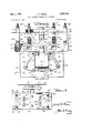
- Fig. 7 is a front elevational view of the modified form of switch illustrated in Fig. 6 with certain of the parts broken away and illustrated in section;
- Fig. 8 is an end view of the modified form of switch shown in Figs. 6 and 7 with parts broken away and illustrated in section for more clearly explaining the construction and operation of the switch system of my invention;
- Fig. 9 is a fragmentary longitudinal sectional view taken on line 99 of Fig. 6;
- Fig. 10 is a fragmentary cross-sectional view taken on line l0l0 of Fig. 6;
- Fig. 9 is a fragmentary longitudinal sectional view taken on line 99 of Fig. 6;
- Fig. 10 is a fragmentary cross-sectional view taken on line l0l0 of Fig.
- FIG. 11 is a horizontal sectional view taken substantially on line llll of Fig. 10;
- Fig. 12 is a fragmentary vertical sectional view taken on line 12-42 of Fig. 10; and
- Fig. 13 is a fragmentary vertical sectional view taken on line l3l3 of Fig. 7 and illustrating the arrangement of contacts carried by the insulated panel structure.
- reference character I indicates a mounting plate of insulation material which may be secured to any available supporting surface anad against which the spacers 2 are secured for mounting the panel of insulation material represented at 3.
- Spacer blocks 4 are secured against panel 3 and form the abutment means against which the mounting foot 5 is secured.
- Bolt members la extend through the spacers '2, panel 3 and spacer blocks 4 and through the inwardly directed end of each mounting foot 5 as shown.
- Nuts lb are secured over the ends of bolts la for securing each mounting foot 5 in position with the planes thereof extending substantially parallel and spaced one from the other.
- Each mounting foot 5 is provided with a multiplicity of parallelly disposed slot 5a through which projections on resilient mounting sheets 6 extend.
- projections are indicated as parallel extending interlocking members 6a which extend through coacting slots 5a in each mountingfoot 5.
- the members 6 also have oppositely directed projections 61) which ex tend through aligned slots lb in coacting mounting plates '1 which serve as mounting means for the electromagnetic actuator represented generally at 8.
- the mounting plates 1 are counterparts of mounting plates and are spacially related thereto through the intermediary of the resilient members 6.
- the oppositely directed projections 6a and 62) on resilient members 8 interlock mounting plates 5 and i and provide a sub stantial shock-proof mounting for the operating unit 8.
- the operating unit 8 comprises an electromagnetic core structure closed upon itself at the end 5 and terminating in pole pieces ill and M at its opposite end.
- An armature shown at E2 provided with a substantially T-shaped head i4 is arranged for longitudinal movement through the.
- a pair of drive links l5 are connected to opposite sides of the armature member l2 and extend through bracket members it mounted on opposite sides of the core structure. Bracketmembers it serve as guides through which the drive links i5 move.
- the drive links are thus confined to movement in a path coincident with the axis of the armature l2 according to the movement of the head 14 of the armature i2 with respect to the pole pieces Ill and H of the magnetic system.
- the operating winding for the magnetic actuator is represented at I? supported on magnetic core structure 8 by means of plates is of insulation material.
- a pad I9 is secured to the end of the magnetic frame 8 and serves as an abutment for limiting the movement of the bar of insulation material shown at 20.
- Bar 20 is carried by the drive links l5 through spacer members 2
- closing of a circuit through the operating winding ll electromagnetically controls the magnetic operating unit so that core structure 8 and the magnetized poles Ii] and l! attract the head M of the movable armature I2 thereby imparting movement through drive links I5 to the bar 23 of insulationmaterial.
- the bar 20 carries a plurality of sets of contactors in spaced position. These contactors are symmetrically arranged with respect to bar 20 and in the form of my invention illustrated in Figs. 1-5. Two sets of contactors are arranged to make before break while another set of contactors are arranged to move from open position to make positionv and make after break, of the aforesaid sets of contactors.
- the contactors 23 and 24 each consistv of a transverse member 25 having a central strip-like projection 26 extending therefrom into a slot 21 formed adjacent each end of the insulated bar 20.
- the slots 21 serve as pockets into which the projecting lug 26 extends.
- the transverse portion 25 of the contactor is constantly urged to a position in which the contactor is seated against bar 20 by means of coil springs 28'.
- Coil springs 28 are each arranged in tubular spring guides 29 which are seated in recesses 33. in the panel of insulation material represented at 3!. Panel 3! is the support for the sets of stationary contacts that coact with the contactors.
- the contactors 23 and 24 have their transverse portions 25 extending in opposite directions on either side of the insulated bar 20 and serving as carriers for the contact members represented at 32 and 33.
- Contact members 32 and 33 are normally urged into closed circuit position with coacting contacts 34 and 35.
- the coacting contacts 34 and are supported on bracket members represented at 35 and 31 extending from panel 3i.
- the bracket members 36 and 3'1 are supported on insulated panel 3! by binding posts 33 and 39.
- These bracket members 33 and 31 extend from panel 3i to positions which support contacts 34 and 35 clear of adjacent structures or ground.
- the contacts are so supported that maximum spacial relation is maintained with respect to objects or circuits of opposite polarity for thereby minimizing spark-over or discharge losses.
- the transverse portions 25 of the contactors 23 and 24 are each provided with central longitudinal extending lugs as which serve as center means for the surrounding coil springs 28.
- coil springs 28' acting in cuplike cylindrical ortubular guides 29 serve to continuously urge contact members 32 and 34 and 33 and 35 into make position. Movement of these contact members to open circuit position from normal closed circuit position is produced upon energization of the operating winding IT.
- the insulated bar 26 also carries a pair of symmetrically arranged contacts which I have shown at :3! each consisting of a transversely extending contactor 52' having a central plate portion 33 which is capable of reciprocative movementwithin the guide frame ea under control of coil spring es.
- the guide frame 53 consists of a strip slotted at opposite sides at Ma and 4317 with a solid central portion 458 and side securing portions 44d and Me which enter aligned grooves as which are milled in the opposite sides of bar 23 and secured thereto by rivet or other suitable means indicated at All.
- the contactor strip e2 substantially floats on coil spring 45 Within the confines of the frame-like member-file.
- the contactors :32 each carry contact members 38 and 49 adjacent opposite ends thereof which are adapted to establish connection with aligned contact members 50' and 5-! respectively supported on panel 35.
- the contact members and 5t are assembled on panel 3'! bymeans of binding posts 52 and 53.
- the spacial relation of contact members 50 and 5! with respect to contact members 18 and 49 is such that a safe distance against spark-over is maintained and the instant of circuit closing between contact members 48 and lli'and contact members 353 and 5! is predetermined at an instant time after the breaking of circuit connection between contact members 35 and 33 and contact members 32 and 33.
- Panel 3 I is supported with respect to the panel of insulation material represented at 3 by means of transversely extending bar member 5d which is supported in bracket device 55 which is secured. to panel 3- by screw means 53. Securing screw 5? extends through panel 3 and bracket 55 engages bar 54 which serves as the supporting means for panel 3!.
- Suitable terminal boards of insulation material represented at 58 aresecured to the frame of the magnetic operating structure 8 as represented at 59. and serve as mounting means for binding posts 60. by which the electromagnetic operating system may be connected in an electrical control circuit.
- I may employ auxiliary spring means for normally maintaining the armature structure in a position ready for actuation upon energization of the operating winding according to the form of my invention illustrated in Figs. 6-13.
- the drive links ii are connected through spacer blocks 2
- One contactor corresponds to the sets of contactors 44 heretofore explained and represented at 62 as mounted in the floating spring support 63.
- is of the type heretofore represented at and is shown in the instant arrangement at (it.
- Contactor 52 carries contact members 65 and 66 (not shown) which i coact with aligned contacts 61 and 68 which are supported upon insulated panel 69.
- Contactor 64 carries contact members 19 and H which coact with contact members I2 and 73 which are supported on brackets 74 and '15 extending from insulated panel 59.
- Contact members 67 and 68 are secured by binding posts 16 and H to insulated panel 89 while contact members 12 and i3 carried by brackets 74 and '15 have electrical connection established therewith by binding posts 18 and 19 carried by panel 69.
- the contactor 64 is maintained in alignment with bar Si by the lug member 89 which enters slot 8
- Lug 89 projects upwardly as represented at 82 to form a centering means for coil spring 83 which is housed within tubular guide 84 set into panel 65.
- a bar support 85 extends transversely from the mounting panel represented at 86 and is secured in bracket 87 by means of securing screw 8%. Bracket 8'! is secured to panel 86 by screw means 89.
- the feature of the form of my invention illustrated in Figs. 6-13 is the provision of the spring member 90 having the convolutions 9
- Coil springs 63 and 83 continuously guide the contactors in their movement I and the switch is thus ready for operation upon closing of the circuit through the actuating magnetic winding l l.
- a spring guide 98 extends from transversely extending bar 85 and serves as a centering means for the hook shaped spring 96.
- spring 95 is cont nrously active in urging the armature member in the position illustrated in Fig. '7 limited by abutment with stop 99.
- a contact supporting panel pairs of spaced contacts carried by said panel, a movable actuator carrying a bar of insulation material displaceable toward and away from said contacts symmetrically therebetween, said bar of insulation material having aligned grooves in opposite sides thereof disposed in alignment with the pairs of spaced contacts on said panel, a substantially U-shaped strip member having a solid central portion and solid end portions interconnected by perforated side portions, the solid end portions of said strip member extending into the aligned rooves in said bar of insulation material and secured thereto and the solid central portion of said strip member extending in spaced relation to said bar of insulation material and directed between said spaced contacts, a conductive bar member extending through the perforated side portions of said strip member transversely of said bar of insulation material, contacts carried by opposite ends of said conductive bar member in alignment with the contacts on said panel and a coil spring interposed between said bar of insulation material and said conductive bar member for continuously urging the contacts on said conductive bar member into yieldable connection
- a contact supporting panel pairs of spaced contacts carried by said panel, a movable actuator carrying a bar of insulation material displaceable toward and away from said contacts symmetrically therebetween, said bar of insulation material having aligned grooves in opposite sides thereof disposed in alignment with the pairs of spaced contacts on said panel, a substantially U-shaped strip member having a solid central portion and solid end portions interconnected by perforated side portions, the solid end portions of said strip member extending into the aligned grooves in said bar of insulation material and secured thereto and the solid central portion of said strip member extending in spaced relation to said bar of insulation material and directed between said spaced contacts, a conductive bar member extendin through the perforated side i portions of said strip member transversely of said bar of insulation material, contacts carried by opposite ends of said conductive bar member in alignment with the contacts on said panel and a coil spring interposed between said bar of insulation material and said conductive bar member for continuously urging the contacts on said conductive bar member into yieldable connection with the
- a movable actuator carrying a bar of insulation material displaceable toward and away from said con tacts symmetrically therebetween, a substantially U-shaped strip member having a solid central portion and solid end portions interconnected by perforated side portions, the solid and portions of said strip member being secured to opposite sides of said bar of insulation material and the solid central portion of said strip member extendin in spaced relation to said bar of insulation material and directed between said spaced contacts, a conductive bar member extending through the perforated side portions of said strip member transversely of said bar of insulation material, contacts carried by opposite ends of said conductive bar member in alignment with the contacts on said panel and a coil spring inter'posed between said bar of insulation material and said conductive bar member for continuously urging the contacts on said conductive bar member into yieldable connection with the contacts on said panel when said bar of insulation material is shifted to actuated position with the solid central portion of said strip member constituting a, limiting stop for said conductive bar member under the action of said coil spring.
- a contact supporting panel pairs of spaced contacts carried by said panel, a movable actuator carrying a bar of insulation material displaceable: toward and away from said contacts symmetrically therebetween, a substantially U-shaped strip member having a solid central portion and solid end portions interconnected by perforated side portions, the solid end porf tions of said strip member being secured to ppositev sidesof said bar of insulation material and the solid central portion of said strip memberextending in spaced relation to said bar of insulation material and directed between said spaced contacts, a conductive bar member extending through the perforated side portions of said strip member transversely of said bar of insulation material, contacts carried by opposite ends of said conductive bar member in alignment with the contacts on said panel and a coil spring interposed between said bar of insulation mate-'- rial and said conductive bar member for continuously urging the contacts on said conductive bar member-into yieldable connection with the contacts on said panel when said bar of insulation material is, shifted to actuated position with the solid central portion
- a panel of insulation material In a high frequency high voltage electrical switch, a panel of insulation material, a pair of brackets depending from opposite sides of said panel and terminating in upwardly directed contacts, a bar of insulation material operative in a plane extending between said contacts, said bar of insulation material being slotted in the upper extremity thereof, a conductive bar member extendin transversely of said bar of insulation material, a strip member extending downwardly into the slotted upper extremity of said bar of insulation material, and supporting said transversely extending bar member and projecting vertically therefrom, said panel of insulation material being recessed immediately above the up" per extremity of said strip member, a tubular member disposed in the said recess and depending downwardly toward said strip member, a coil spring centered within said tubular member and extending around said strip member and operative against said conductive bar member, and contacts carried by the lower races of the opposite ends of said conductive bar member and operative to establish electrical connection with the upper faces of the contacts carried by said brackets.
- a panel of insulation material In a high frequency high voltage electrical switch, a panel of insulation material, a pair of brackets depending from opposite sides of said panel and terminating in upwardly directed contacts, a bar of insulation material operative ina plane extending between said contacts, said bar of insulating material being slotted in the upper extremity thereof, a conductive bar member ex-' tending transversely of said bar of insulation material, a strip member extendin downwardly into the slotted upper extremity of said bar of insulation material, and supporting, said transversely extending bar member and projecting vertically therefrom, said panel of insulation material being recessed immediately above the upper extremity of said strip member, a tubular member disposed in the said recess and depending downwardly toward said strip member, a coil spring centered within said tubular member and extending around said strip member and opera tive against said conductive bar member, and contacts carried by the lower faces of the opposite ends of said conductive bar member and operative to establish electrical connection with the upper faces of the contacts carried by said brackets, said conductive bar member having
- a panel of insulation material In a high frequency high voltage electrical switch, a panel of insulation material, a pair of brackets depending from opposite sides of said panel and terminating in upwardly directed con-'- tacts, a bar of insulation material operative in a plane extending between said contacts, said bar of insulation material being slotted in the upper extremity thereof, a conductive bar member extending transversely of said bar of insulation material and having a central flattened portion and a pair of upwardly directed end portions each carrying contacts thereon with contacting faces adapted to establish electrical connection with the aforesaid upwardly directed contacts,- a thimble-like device carried by said panel of insulation material in alignment with the flattened central portion of said conductive bar member, a
- strip member extending vertically from the slotted upper extremity of said bar of insulation material and through the flat central portion of said conductive bar member and extending vertically therefrom, and a coil spring disposed in saidthimble-likemember and directed toward said conductive bar member and extending around said strip member and seated against the flat central portion of said conductive bar member for normally urging the contacts on said conductive bar member into" electrical connec tion with the contacts on said brackets preparatory to a circuit opening operation upon vertical movement of said bar of insulation material.
Landscapes
- Push-Button Switches (AREA)
Description
Jan. 1, 1952 J FRESE 2,580,418
HIGH-FREQUENCY ELECTRICAL APPARATUS Filed May 27, 1944 6 Sheets-Sheet l grwwm 90/349192 5 1 Emu 6 Sheets-Sheet 2 Jan. 1, 1952 J. F. FRESE HIGH-FREQUENCY ELECTRICAL APPARATUS Filed May 27, 1944 1 l I I l l- 1 n T n A (L 5 0/0129: dnfi 8 Emma? Jan. 1, 1952 J. F. FRESE 2,580,418
HIGH-FREQUENCY ELECTRICAL APPARATUS Filed May 27, 1944 6 Sheets-Sheet 3 awumvlm (To/M 04? E7 gt wow,
Jam. 1, 1952 J. F. FRESE 2,580,418
HIGH-FREQUENCY ELECTRICAL APPARATUS Filed May 27, 1944 6 Sheets-Sheet 4 gin/um 0 a 0 3 0/0230? it wow Jan. 1, 1952 J. F. FRESE HIGH-FREQUENCY ELECTRICAL APPARATUS 6 Sheets-Sheet 5 Filed May 27, 1944 ZOO/3&5)? f @4200, 3% d 5 1952 J. F. FRESE 2,580,413
HIGH-FREQUENCY ELECTRICAL APPARATUS Filed May 27, 1944 6 Sheets-Sheet 6 Tail Patented Jan. 1, 1952 HIGH-FREQUEN CY ELECTRICAL APPARATUS Joseph F. Frese, Baltimore, Md., assignor to The Monitor Controller Company, Baltimore, Md., a corporation of Maryland Application May 27, 1944, Serial No. 537,703
7 Claims.
My invention relates broadly to high frequency high voltage electrical switches and contactors and more particularly to an improved construction of electromagnetically actuated high frequency switch and contactor system.
One of the objects of my invention is to provide an improved construction of high frequency electrical switch and contactor system which is efficient in operation and capable of manufacture and production inexpensively on a mass production scale.
Another object of my invention is to provide a high frequency electrical switch and contactor system having means for maintaining an alignment of groups of contactors with respect to coacting contact members while allowing safe spacial displacement of the contactors with respect to the coacting contacts for high potential operation.
Another object of my invention is to provide a construction of high voltage high frequency electrical switch system including a carrier for a multiplicity of contacts which is electromagnetically displaceable for closing a multiplicity of contacts with yieldable means for individually maintaining the contactors in alignment with the coacting contacts.
Still another object of my invention is to provide a construction of high voltage high frequency electrical switch in which a carrier of insulation material is arranged to be displaced by an electromagnetic actuator for controlling the opening and closing of a multiplicity of electrical contactors and coacting contacts where the contactors are each supported in spacial relation on the carrier.
Still another object of my invention is to provide an improved construction of electrical contactors for cooperation with coacting contacts including means for yieldably mounting the contactor for maintaining alignment of the contactor with respect to the coacting contacts throughout the path of travel of displaceable supporting means for the contactor.
Other and further objects of my invention reside in a construction of aligning means for multiplicity of displaceable cont-actors in an electrical switch assembly as set forth more fully in the specification hereinafter following by reference to the accompanying drawings in which: 7 Figure l is a front elevational view of the high frequency high voltage switch of my invention with parts associated with the contact system broken away and illustrated in section; Fig. 2 is an end view of the switch and contact system of my invention with certain of the parts broken away and illustrated in section; Fig. 3 is a top plan view of the switch and contact system of my invention with the contact supporting panel broken away and illustrated in section; Fig. 4 is a fragmentary vertical sectional view through the switch and contact system taken on line 4-4 of Fig. 1; Fig. 5 is a bottom plan view of the electromagnetic actuator of the switch system of my invention with certain of the parts broken away and illustrated in section; Fig. 6 is a top plan view of a modified form of high frequency high voltage switch embodying my invention; Fig. 7 is a front elevational view of the modified form of switch illustrated in Fig. 6 with certain of the parts broken away and illustrated in section; Fig. 8 is an end view of the modified form of switch shown in Figs. 6 and 7 with parts broken away and illustrated in section for more clearly explaining the construction and operation of the switch system of my invention; Fig. 9 is a fragmentary longitudinal sectional view taken on line 99 of Fig. 6; Fig. 10 is a fragmentary cross-sectional view taken on line l0l0 of Fig. 6; Fig. 11 is a horizontal sectional view taken substantially on line llll of Fig. 10; Fig. 12 is a fragmentary vertical sectional view taken on line 12-42 of Fig. 10; and Fig. 13 is a fragmentary vertical sectional view taken on line l3l3 of Fig. 7 and illustrating the arrangement of contacts carried by the insulated panel structure.
Referring to the drawings in detail reference character I indicates a mounting plate of insulation material which may be secured to any available supporting surface anad against which the spacers 2 are secured for mounting the panel of insulation material represented at 3. Spacer blocks 4 are secured against panel 3 and form the abutment means against which the mounting foot 5 is secured. Bolt members la extend through the spacers '2, panel 3 and spacer blocks 4 and through the inwardly directed end of each mounting foot 5 as shown. Nuts lb are secured over the ends of bolts la for securing each mounting foot 5 in position with the planes thereof extending substantially parallel and spaced one from the other. Each mounting foot 5 is provided with a multiplicity of parallelly disposed slot 5a through which projections on resilient mounting sheets 6 extend. These projections are indicated as parallel extending interlocking members 6a which extend through coacting slots 5a in each mountingfoot 5. The members 6 also have oppositely directed projections 61) which ex tend through aligned slots lb in coacting mounting plates '1 which serve as mounting means for the electromagnetic actuator represented generally at 8. The mounting plates 1 are counterparts of mounting plates and are spacially related thereto through the intermediary of the resilient members 6. The oppositely directed projections 6a and 62) on resilient members 8 interlock mounting plates 5 and i and provide a sub stantial shock-proof mounting for the operating unit 8.
The operating unit 8 comprises an electromagnetic core structure closed upon itself at the end 5 and terminating in pole pieces ill and M at its opposite end. An armature shown at E2 provided with a substantially T-shaped head i4 is arranged for longitudinal movement through the.
core structure of the magnetic actuator. A pair of drive links l5 are connected to opposite sides of the armature member l2 and extend through bracket members it mounted on opposite sides of the core structure. Bracketmembers it serve as guides through which the drive links i5 move. The drive links are thus confined to movement in a path coincident with the axis of the armature l2 according to the movement of the head 14 of the armature i2 with respect to the pole pieces Ill and H of the magnetic system. The operating winding for the magnetic actuator is represented at I? supported on magnetic core structure 8 by means of plates is of insulation material.
A pad I9 is secured to the end of the magnetic frame 8 and serves as an abutment for limiting the movement of the bar of insulation material shown at 20. Bar 20 is carried by the drive links l5 through spacer members 2| and interconnecting bolts 22 as shown in Figs. 1 and 2. Thus closing of a circuit through the operating winding ll electromagnetically controls the magnetic operating unit so that core structure 8 and the magnetized poles Ii] and l! attract the head M of the movable armature I2 thereby imparting movement through drive links I5 to the bar 23 of insulationmaterial.
The bar 20 carries a plurality of sets of contactors in spaced position. These contactors are symmetrically arranged with respect to bar 20 and in the form of my invention illustrated in Figs. 1-5. Two sets of contactors are arranged to make before break while another set of contactors are arranged to move from open position to make positionv and make after break, of the aforesaid sets of contactors.
I have shown make before break contactors at opposite ends of the insulated bar 20 at 23 and 24. The contactors 23 and 24 each consistv of a transverse member 25 having a central strip-like projection 26 extending therefrom into a slot 21 formed adjacent each end of the insulated bar 20. The slots 21 serve as pockets into which the projecting lug 26 extends. The transverse portion 25 of the contactor is constantly urged to a position in which the contactor is seated against bar 20 by means of coil springs 28'. Coil springs 28 are each arranged in tubular spring guides 29 which are seated in recesses 33. in the panel of insulation material represented at 3!. Panel 3! is the support for the sets of stationary contacts that coact with the contactors.
The contactors 23 and 24 have their transverse portions 25 extending in opposite directions on either side of the insulated bar 20 and serving as carriers for the contact members represented at 32 and 33. Contact members 32 and 33 are normally urged into closed circuit position with coacting contacts 34 and 35. The coacting contacts 34 and are supported on bracket members represented at 35 and 31 extending from panel 3i. The bracket members 36 and 3'1 are supported on insulated panel 3! by binding posts 33 and 39. These bracket members 33 and 31 extend from panel 3i to positions which support contacts 34 and 35 clear of adjacent structures or ground. The contacts are so supported that maximum spacial relation is maintained with respect to objects or circuits of opposite polarity for thereby minimizing spark-over or discharge losses. The spacial relation of the inwardly directed ends of brackets as and 3'! is such that bar 23 of insulation material may reciprocate therebetween and the proportions are such that contact is made between contact members 32 and 35 and contact members 33 and 36 before insulated bar 20 reaches a position abutting with pad IS. The transverse portions 25 of the contactors 23 and 24 are each provided with central longitudinal extending lugs as which serve as center means for the surrounding coil springs 28. Thus coil springs 28' acting in cuplike cylindrical ortubular guides 29 serve to continuously urge contact members 32 and 34 and 33 and 35 into make position. Movement of these contact members to open circuit position from normal closed circuit position is produced upon energization of the operating winding IT.
The insulated bar 26 also carries a pair of symmetrically arranged contacts which I have shown at :3! each consisting of a transversely extending contactor 52' having a central plate portion 33 which is capable of reciprocative movementwithin the guide frame ea under control of coil spring es. The guide frame 53 consists of a strip slotted at opposite sides at Ma and 4317 with a solid central portion 458 and side securing portions 44d and Me which enter aligned grooves as which are milled in the opposite sides of bar 23 and secured thereto by rivet or other suitable means indicated at All. The contactor strip e2 substantially floats on coil spring 45 Within the confines of the frame-like member-file. The contactors :32 each carry contact members 38 and 49 adjacent opposite ends thereof which are adapted to establish connection with aligned contact members 50' and 5-! respectively supported on panel 35. The contact members and 5t are assembled on panel 3'! bymeans of binding posts 52 and 53. The spacial relation of contact members 50 and 5! with respect to contact members 18 and 49 is such that a safe distance against spark-over is maintained and the instant of circuit closing between contact members 48 and lli'and contact members 353 and 5! is predetermined at an instant time after the breaking of circuit connection between contact members 35 and 33 and contact members 32 and 33.
Panel 3 I is supported with respect to the panel of insulation material represented at 3 by means of transversely extending bar member 5d which is supported in bracket device 55 which is secured. to panel 3- by screw means 53. Securing screw 5? extends through panel 3 and bracket 55 engages bar 54 which serves as the supporting means for panel 3!.
Suitable terminal boards of insulation material represented at 58 aresecured to the frame of the magnetic operating structure 8 as represented at 59. and serve as mounting means for binding posts 60. by which the electromagnetic operating system may be connected in an electrical control circuit.
I may employ auxiliary spring means for normally maintaining the armature structure in a position ready for actuation upon energization of the operating winding according to the form of my invention illustrated in Figs. 6-13. In this arrangement the drive links ii are connected through spacer blocks 2| and bolt members 22 (shown in Figs. 1 and 2) to opposite sides of an insulated bar of shorter proportions represented at 6| for supporting dissimilar unit contactors adjacent opposite ends thereof. One contactor corresponds to the sets of contactors 44 heretofore explained and represented at 62 as mounted in the floating spring support 63. The contactor at the opposite end of bar 6| is of the type heretofore represented at and is shown in the instant arrangement at (it. Contactor 52 carries contact members 65 and 66 (not shown) which i coact with aligned contacts 61 and 68 which are supported upon insulated panel 69. Contactor 64 carries contact members 19 and H which coact with contact members I2 and 73 which are supported on brackets 74 and '15 extending from insulated panel 59. Contact members 67 and 68 are secured by binding posts 16 and H to insulated panel 89 while contact members 12 and i3 carried by brackets 74 and '15 have electrical connection established therewith by binding posts 18 and 19 carried by panel 69.
The contactor 64 is maintained in alignment with bar Si by the lug member 89 which enters slot 8| in insulated bar 6|. Lug 89 projects upwardly as represented at 82 to form a centering means for coil spring 83 which is housed within tubular guide 84 set into panel 65. A bar support 85 extends transversely from the mounting panel represented at 86 and is secured in bracket 87 by means of securing screw 8%. Bracket 8'! is secured to panel 86 by screw means 89.
The feature of the form of my invention illustrated in Figs. 6-13 is the provision of the spring member 90 having the convolutions 9| thereof secured concentrically about member 92 extending transversely of bracket 81 and having one end thereof at 95 anchored in a socket 96 formed in bar 85 and the other end thereof shaped as a hook at 94 which continuously bears against the bar of insulat on material 5! tending to urge bar Bl to a position in which the armature is retracted and contact members 12-'!!! and ES-1| closed and contact members 6561 and 66-68 maintained open. Coil springs 63 and 83 continuously guide the contactors in their movement I and the switch is thus ready for operation upon closing of the circuit through the actuating magnetic winding l l. A spring guide 98 extends from transversely extending bar 85 and serves as a centering means for the hook shaped spring 96. Thus spring 95 is cont nrously active in urging the armature member in the position illustrated in Fig. '7 limited by abutment with stop 99.
Although the arrangement of contactors illustrated in Figs. 6-13 is unsymmetrical in that one set of contactors are maintained open while the other set of contactors are maintained closed, nevertheless accurate and efficient operation of the switch system is maintained due to the centering action of the coil springs and the resilient action of the wire hook shaped spring.
Both forms of my invention have been found to be highly practical in construction and successful tion in certain preferred embodiments I realize that modifications maybe made and I desire that it be understood that no limitations upon my invention are intended other than may be imposed by the scope of the appended claims.
What I claim as new and desire to secure by Letters Patent of the United States is as follows:
1. In a high frequency high voltage electrical switch, a contact supporting panel, pairs of spaced contacts carried by said panel, a movable actuator carrying a bar of insulation material displaceable toward and away from said contacts symmetrically therebetween, said bar of insulation material having aligned grooves in opposite sides thereof disposed in alignment with the pairs of spaced contacts on said panel, a substantially U-shaped strip member having a solid central portion and solid end portions interconnected by perforated side portions, the solid end portions of said strip member extending into the aligned rooves in said bar of insulation material and secured thereto and the solid central portion of said strip member extending in spaced relation to said bar of insulation material and directed between said spaced contacts, a conductive bar member extending through the perforated side portions of said strip member transversely of said bar of insulation material, contacts carried by opposite ends of said conductive bar member in alignment with the contacts on said panel and a coil spring interposed between said bar of insulation material and said conductive bar member for continuously urging the contacts on said conductive bar member into yieldable connection with the contacts on said panel when said bar of insulation material is shifted to actuated position with the solid central portion of said strip member constituting a limiting stop for said conductive bar member under the action of said coil spring.
2. In a high frequency high voltage electrical switch, a contact supporting panel, pairs of spaced contacts carried by said panel, a movable actuator carrying a bar of insulation material displaceable toward and away from said contacts symmetrically therebetween, said bar of insulation material having aligned grooves in opposite sides thereof disposed in alignment with the pairs of spaced contacts on said panel, a substantially U-shaped strip member having a solid central portion and solid end portions interconnected by perforated side portions, the solid end portions of said strip member extending into the aligned grooves in said bar of insulation material and secured thereto and the solid central portion of said strip member extending in spaced relation to said bar of insulation material and directed between said spaced contacts, a conductive bar member extendin through the perforated side i portions of said strip member transversely of said bar of insulation material, contacts carried by opposite ends of said conductive bar member in alignment with the contacts on said panel and a coil spring interposed between said bar of insulation material and said conductive bar member for continuously urging the contacts on said conductive bar member into yieldable connection with the contacts on said panel when said bar of insulation material is shifted to actuated position i with the solid central portion of said strip memin operation. While I have described my invenber constituting a limiting stop for said conductive bar member under the action of said coil spring, said conductive bar extending upwardly on each side of the solid central portion of said strip member for centering said conductive bar with respect to the some central portion of said strip memben 3. In a high frequency" high voltage electrical switch, a contact supporting panel, pairs of.
spaced contacts carried by said panel, a movable actuator carrying a bar of insulation material displaceable toward and away from said con tacts symmetrically therebetween, a substantially U-shaped strip member having a solid central portion and solid end portions interconnected by perforated side portions, the solid and portions of said strip member being secured to opposite sides of said bar of insulation material and the solid central portion of said strip member extendin in spaced relation to said bar of insulation material and directed between said spaced contacts, a conductive bar member extending through the perforated side portions of said strip member transversely of said bar of insulation material, contacts carried by opposite ends of said conductive bar member in alignment with the contacts on said panel and a coil spring inter'posed between said bar of insulation material and said conductive bar member for continuously urging the contacts on said conductive bar member into yieldable connection with the contacts on said panel when said bar of insulation material is shifted to actuated position with the solid central portion of said strip member constituting a, limiting stop for said conductive bar member under the action of said coil spring.
4. In a. high frequency high voltage electrical switch, a contact supporting panel, pairs of spaced contacts carried by said panel, a movable actuator carrying a bar of insulation material displaceable: toward and away from said contacts symmetrically therebetween, a substantially U-shaped strip member having a solid central portion and solid end portions interconnected by perforated side portions, the solid end porf tions of said strip member being secured to ppositev sidesof said bar of insulation material and the solid central portion of said strip memberextending in spaced relation to said bar of insulation material and directed between said spaced contacts, a conductive bar member extending through the perforated side portions of said strip member transversely of said bar of insulation material, contacts carried by opposite ends of said conductive bar member in alignment with the contacts on said panel and a coil spring interposed between said bar of insulation mate-'- rial and said conductive bar member for continuously urging the contacts on said conductive bar member-into yieldable connection with the contacts on said panel when said bar of insulation material is, shifted to actuated position with the solid central portion of said strip member constituting alimiting stop for said conductive bar member under the action of said coil spring, said conductive bar member extending upwardly on each side of the solid central portion of said strip member for centering said conductive bar with respect to said solid central portion of said strip member.
'. In a high frequency high voltage electrical switch, a panel of insulation material, a pair of brackets depending from opposite sides of said panel and terminating in upwardly directed contacts, a bar of insulation material operative in a plane extending between said contacts, said bar of insulation material being slotted in the upper extremity thereof, a conductive bar member extendin transversely of said bar of insulation material, a strip member extending downwardly into the slotted upper extremity of said bar of insulation material, and supporting said transversely extending bar member and projecting vertically therefrom, said panel of insulation material being recessed immediately above the up" per extremity of said strip member, a tubular member disposed in the said recess and depending downwardly toward said strip member, a coil spring centered within said tubular member and extending around said strip member and operative against said conductive bar member, and contacts carried by the lower races of the opposite ends of said conductive bar member and operative to establish electrical connection with the upper faces of the contacts carried by said brackets.
6, In a high frequency high voltage electrical switch, a panel of insulation material, a pair of brackets depending from opposite sides of said panel and terminating in upwardly directed contacts, a bar of insulation material operative ina plane extending between said contacts, said bar of insulating material being slotted in the upper extremity thereof, a conductive bar member ex-' tending transversely of said bar of insulation material, a strip member extendin downwardly into the slotted upper extremity of said bar of insulation material, and supporting, said transversely extending bar member and projecting vertically therefrom, said panel of insulation material being recessed immediately above the upper extremity of said strip member, a tubular member disposed in the said recess and depending downwardly toward said strip member, a coil spring centered within said tubular member and extending around said strip member and opera tive against said conductive bar member, and contacts carried by the lower faces of the opposite ends of said conductive bar member and operative to establish electrical connection with the upper faces of the contacts carried by said brackets, said conductive bar member having a flattened portion immediately adjacent said strip member and forming a seat for said coil spring and ex-' tending upwardly on each side of said coil spring for centering said coil spring with respect to said strip member.
'7. In a high frequency high voltage electrical switch, a panel of insulation material, a pair of brackets depending from opposite sides of said panel and terminating in upwardly directed con-'- tacts, a bar of insulation material operative in a plane extending between said contacts, said bar of insulation material being slotted in the upper extremity thereof, a conductive bar member extending transversely of said bar of insulation material and having a central flattened portion and a pair of upwardly directed end portions each carrying contacts thereon with contacting faces adapted to establish electrical connection with the aforesaid upwardly directed contacts,- a thimble-like device carried by said panel of insulation material in alignment with the flattened central portion of said conductive bar member, a
. strip member extending vertically from the slotted upper extremity of said bar of insulation material and through the flat central portion of said conductive bar member and extending vertically therefrom, and a coil spring disposed in saidthimble-likemember and directed toward said conductive bar member and extending around said strip member and seated against the flat central portion of said conductive bar member for normally urging the contacts on said conductive bar member into" electrical connec tion with the contacts on said brackets preparatory to a circuit opening operation upon vertical movement of said bar of insulation material.
JOSEPH F. FRESE.
REFERENCES CITED The following references are of record in the file of this patent:
Number UNITED STATES PATENTS Name Date Wilms Feb. 16, 1937 Bierenfeid et a1 Apr. 22, 1941 Pierce Mar. 17, 1942 Van Valkenburg et a1. -Dec. 15, 1942
Publications (1)
| Publication Number | Publication Date |
|---|---|
| US2580418A true US2580418A (en) | 1952-01-01 |
Family
ID=3438597
Family Applications (1)
| Application Number | Title | Priority Date | Filing Date |
|---|---|---|---|
| US2580418D Expired - Lifetime US2580418A (en) | High-frequency electrical |
Country Status (1)
| Country | Link |
|---|---|
| US (1) | US2580418A (en) |
Cited By (3)
| Publication number | Priority date | Publication date | Assignee | Title |
|---|---|---|---|---|
| US2649521A (en) * | 1950-04-13 | 1953-08-18 | Furnas Electric Co | Magnetic switch |
| US2895026A (en) * | 1957-04-26 | 1959-07-14 | Gen Motors Corp | Switch operating means |
| US3235683A (en) * | 1961-04-12 | 1966-02-15 | Beeman Lyle | Air compressor control mechanism |
Citations (4)
| Publication number | Priority date | Publication date | Assignee | Title |
|---|---|---|---|---|
| US2071149A (en) * | 1935-07-11 | 1937-02-16 | Allen Bradley Co | Electric switch |
| US2239031A (en) * | 1936-08-24 | 1941-04-22 | Square D Co | Electric switch |
| US2276698A (en) * | 1939-09-30 | 1942-03-17 | Westinghouse Electric & Mfg Co | Contactor |
| US2304972A (en) * | 1939-11-24 | 1942-12-15 | Square D Co | Electric switch |
-
0
- US US2580418D patent/US2580418A/en not_active Expired - Lifetime
Patent Citations (4)
| Publication number | Priority date | Publication date | Assignee | Title |
|---|---|---|---|---|
| US2071149A (en) * | 1935-07-11 | 1937-02-16 | Allen Bradley Co | Electric switch |
| US2239031A (en) * | 1936-08-24 | 1941-04-22 | Square D Co | Electric switch |
| US2276698A (en) * | 1939-09-30 | 1942-03-17 | Westinghouse Electric & Mfg Co | Contactor |
| US2304972A (en) * | 1939-11-24 | 1942-12-15 | Square D Co | Electric switch |
Cited By (3)
| Publication number | Priority date | Publication date | Assignee | Title |
|---|---|---|---|---|
| US2649521A (en) * | 1950-04-13 | 1953-08-18 | Furnas Electric Co | Magnetic switch |
| US2895026A (en) * | 1957-04-26 | 1959-07-14 | Gen Motors Corp | Switch operating means |
| US3235683A (en) * | 1961-04-12 | 1966-02-15 | Beeman Lyle | Air compressor control mechanism |
Similar Documents
| Publication | Publication Date | Title |
|---|---|---|
| US3296567A (en) | Electric control device | |
| US2276698A (en) | Contactor | |
| GB480026A (en) | Improvements in and relating to electromagnetic devices | |
| GB2117974A (en) | Power switching device | |
| US2266536A (en) | Electric relay | |
| CN208045411U (en) | A high voltage DC contactor | |
| US2580418A (en) | High-frequency electrical | |
| US2448650A (en) | Electric control switch | |
| US2516772A (en) | Cross-wire switch | |
| US2562091A (en) | Relay | |
| US3320392A (en) | Electric control device with improved contact structure | |
| US3736538A (en) | Electric control devices with mechanical interlock | |
| US3519967A (en) | Relay with modular contact assembly | |
| CN213781936U (en) | A non-polar high voltage DC contactor | |
| CN112382533A (en) | Non-polar high-voltage direct-current contactor | |
| US2945107A (en) | Electrical relays | |
| KR102827387B1 (en) | Vehicle contactors, vehicle charging and power distribution systems, charging piles, and vehicles | |
| US2956140A (en) | Electromagnetic relay spring assembly | |
| US3088058A (en) | Contactor | |
| US2326760A (en) | Electric snap switch | |
| US3673525A (en) | Contactor | |
| US2312493A (en) | Relay | |
| US2867691A (en) | Crossbar switch | |
| US4652707A (en) | Power switch | |
| US3277409A (en) | Electromagnetic relay assembly having a flat coil and whose armature assembly is formed with a deformable stem |