US2577458A - Apparatus for regulating air pressure in automobile tires - Google Patents
Apparatus for regulating air pressure in automobile tires Download PDFInfo
- Publication number
- US2577458A US2577458A US781894A US78189447A US2577458A US 2577458 A US2577458 A US 2577458A US 781894 A US781894 A US 781894A US 78189447 A US78189447 A US 78189447A US 2577458 A US2577458 A US 2577458A
- Authority
- US
- United States
- Prior art keywords
- air
- pressure
- automobile
- valve
- air pressure
- Prior art date
- Legal status (The legal status is an assumption and is not a legal conclusion. Google has not performed a legal analysis and makes no representation as to the accuracy of the status listed.)
- Expired - Lifetime
Links
- 230000001105 regulatory effect Effects 0.000 title description 2
- 238000012856 packing Methods 0.000 description 4
- 238000005192 partition Methods 0.000 description 4
- 230000008520 organization Effects 0.000 description 2
- 208000009989 Posterior Leukoencephalopathy Syndrome Diseases 0.000 description 1
- 241001225883 Prosopis kuntzei Species 0.000 description 1
- 230000015572 biosynthetic process Effects 0.000 description 1
- 238000004891 communication Methods 0.000 description 1
- 239000000470 constituent Substances 0.000 description 1
- 230000001276 controlling effect Effects 0.000 description 1
- 239000000463 material Substances 0.000 description 1
- 238000000034 method Methods 0.000 description 1
- 238000007789 sealing Methods 0.000 description 1
Images
Classifications
-
- B—PERFORMING OPERATIONS; TRANSPORTING
- B60—VEHICLES IN GENERAL
- B60C—VEHICLE TYRES; TYRE INFLATION; TYRE CHANGING; CONNECTING VALVES TO INFLATABLE ELASTIC BODIES IN GENERAL; DEVICES OR ARRANGEMENTS RELATED TO TYRES
- B60C23/00—Devices for measuring, signalling, controlling, or distributing tyre pressure or temperature, specially adapted for mounting on vehicles; Arrangement of tyre inflating devices on vehicles, e.g. of pumps or of tanks; Tyre cooling arrangements
- B60C23/001—Devices for manually or automatically controlling or distributing tyre pressure whilst the vehicle is moving
- B60C23/003—Devices for manually or automatically controlling or distributing tyre pressure whilst the vehicle is moving comprising rotational joints between vehicle-mounted pressure sources and the tyres
- B60C23/00345—Details of the rotational joints
-
- B—PERFORMING OPERATIONS; TRANSPORTING
- B60—VEHICLES IN GENERAL
- B60C—VEHICLE TYRES; TYRE INFLATION; TYRE CHANGING; CONNECTING VALVES TO INFLATABLE ELASTIC BODIES IN GENERAL; DEVICES OR ARRANGEMENTS RELATED TO TYRES
- B60C23/00—Devices for measuring, signalling, controlling, or distributing tyre pressure or temperature, specially adapted for mounting on vehicles; Arrangement of tyre inflating devices on vehicles, e.g. of pumps or of tanks; Tyre cooling arrangements
- B60C23/001—Devices for manually or automatically controlling or distributing tyre pressure whilst the vehicle is moving
- B60C23/003—Devices for manually or automatically controlling or distributing tyre pressure whilst the vehicle is moving comprising rotational joints between vehicle-mounted pressure sources and the tyres
- B60C23/00309—Devices for manually or automatically controlling or distributing tyre pressure whilst the vehicle is moving comprising rotational joints between vehicle-mounted pressure sources and the tyres characterised by the location of the components, e.g. valves, sealings, conduits or sensors
- B60C23/00318—Devices for manually or automatically controlling or distributing tyre pressure whilst the vehicle is moving comprising rotational joints between vehicle-mounted pressure sources and the tyres characterised by the location of the components, e.g. valves, sealings, conduits or sensors on the wheels or the hubs
-
- B—PERFORMING OPERATIONS; TRANSPORTING
- B60—VEHICLES IN GENERAL
- B60C—VEHICLE TYRES; TYRE INFLATION; TYRE CHANGING; CONNECTING VALVES TO INFLATABLE ELASTIC BODIES IN GENERAL; DEVICES OR ARRANGEMENTS RELATED TO TYRES
- B60C23/00—Devices for measuring, signalling, controlling, or distributing tyre pressure or temperature, specially adapted for mounting on vehicles; Arrangement of tyre inflating devices on vehicles, e.g. of pumps or of tanks; Tyre cooling arrangements
- B60C23/001—Devices for manually or automatically controlling or distributing tyre pressure whilst the vehicle is moving
- B60C23/003—Devices for manually or automatically controlling or distributing tyre pressure whilst the vehicle is moving comprising rotational joints between vehicle-mounted pressure sources and the tyres
- B60C23/00345—Details of the rotational joints
- B60C23/00347—Details of the rotational joints comprising two or more feedthrough
-
- B—PERFORMING OPERATIONS; TRANSPORTING
- B60—VEHICLES IN GENERAL
- B60C—VEHICLE TYRES; TYRE INFLATION; TYRE CHANGING; CONNECTING VALVES TO INFLATABLE ELASTIC BODIES IN GENERAL; DEVICES OR ARRANGEMENTS RELATED TO TYRES
- B60C23/00—Devices for measuring, signalling, controlling, or distributing tyre pressure or temperature, specially adapted for mounting on vehicles; Arrangement of tyre inflating devices on vehicles, e.g. of pumps or of tanks; Tyre cooling arrangements
- B60C23/001—Devices for manually or automatically controlling or distributing tyre pressure whilst the vehicle is moving
- B60C23/003—Devices for manually or automatically controlling or distributing tyre pressure whilst the vehicle is moving comprising rotational joints between vehicle-mounted pressure sources and the tyres
- B60C23/00354—Details of valves
Definitions
- the pneumatic tubes within the tires are tubularly connected with a control valve compartment, which in turn is supplied with air from a compressor operated by the engine of the automobile.
- An object of my invention is to provide a tireinflating and. air-controlling means which has pneumatic connection with all the tires of an automobile, and with an indicator and controllingmeans located upon the instrument board of the automobile.
- Another object of my invention is the inclusion 'therein of an indicator upon the instrument board of an automobile to set the tire inflation to any desired pressure.
- a further object of my invention is the inclusion therein of an automatically operated series of valves to keep the inflated tires to the pressure set by the control unit on the instrument board of an automobile.
- a still further object of my invention is the inclusion therein of a swivel connecting means between the chassis and wheels of an automobile to permit the flow of air to and from the wheels.
- a still further object of this invention is the provision of an organization in which the constituent elements are so arranged structurally andfunctionally as to assure improved results with materials and members which may be manufactured at reasonable cost, may be easily assembled, and which will be eflicient in operation with minimum wear to the parts.
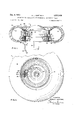
- Figure 1 is a sectional view through an automobile wheel approximately at the hub and brake drum, and shows parts in section.
- Figure 2 is a side elevational view, partly broken away at the line 2-2 of Figure 1, of an automobile wheel showing the swivel connecting means for supplying air to the inner tube.
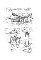
- Figure 3 is a fragmentary section View, showing a modified form of a swivel connection at the wheel hub.
- Figure 4 is a fragmentary view, showing a portion of the instrument board in full view, and an air compartment in section.
- FIG. 5 is a diagrammatic view, in plan, showing a chassis and the tubular connections to the Referring in detail to the parts, designates an automobile wheel'carrying an outer shoe I2,
- the drum H is suitably secured to a fiat, annular member l9, which forms the inner wall of the hub l6, and to which there is attached, in any suitable manner, a valve chamber 20, having an outer air compart ment 2
- the said divide ing partition 23, has an air inlet valve 24, and
- Theair compartment 2 I i connected with the inner tube I3, through the flexible tube 28, and the valve 24, is adapted to lock the air in theinnertube regardless of the air pressure v therein.
- An annular air channel 33 is provided, into which air is directed from the flexible tube connection 34, and a channel 35, in the said instrument board 43, and indicates the pressure of the air in the tires.
- a pressure control compartment 4 4,- is provic ledf in the box 31, and is separated from the'first" mentioned distributor compartment 38, by a partition 45, having an opening 45, whicha valve 41, is seated and held withinthe openinga by a crossbar 48, slidable upon rods 49, which are fixed upon the partition 45. mounted upon the upper ends of the said rods 49,4sa second crossbar 5ll, the upward movement of which is limited by thenut heads, 5I.
- Springs 52 engage around the saidrods 49-, between the crossbars 48 and 50. The pressure of the said springs against the crossbar 48, will hold the valve 41, upon its: seat, and thispressure may be varied by adjusting the cross bar 50, toshorten the distance between the two said crossbars and increasethe'pressure -of the springs.
- the said flexible cable is also connected with a manipulating, knob. 51, turnable'upon adial 58 on the instrument board 43.
- the position of-the cross bar 50, with respect to the crossbar 48, will determine the pressure of the springs 52 which, in turn, will transmit. their pressureto Slidalili the valve 41.
- the said pressure is nieasured' by pounds as indicated by. the numerals upon the dialv 58.
- Figure: 3 illustratesamodified form of packing and air sealing meansbetween the stationary member upon thechassis ofthe car-and the'rotatingI member upon, the wheels.
- the said modified" form shows thfstatioriary member designated by the numeral I30',1aridhas formed thereon a stem I3'I, which has a' chan'nel I32, and which providesa means. for'connectm g the tube 34 The inner end' ofthclia'nnel' I32,
- the knob 51 on the instrument board is set to the pressure desired and the springs 52, in the control compartment 44, will exert a corresponding pressure againstthevalve 41. will enter from the compressed, into thedistributor compartment 38, through the inlet tube 40, and will register on the gauge 42. The air in the distributor compartment-38, will-pass through the tube connectloiis- 35,, td tlf'flexible connecting members 34,
- Means, not shown may be-provided to discontinue the compressor operation when same is -not required.-
- a pressure relief T valve means having a manually adjustable air pressure indicator and a dial disposed in communication compartments-air inlet valves and-air-pressure controLvalves -in the valve-cliambersdisposed between the said air. inlet and outlet compartments, thesaidair inlet valvesadapted to maintain-the desired air pressure in-the tires andthe said air pressure control valves: adaptedto release-any excessive air pressure -from the tires.
Landscapes
- Engineering & Computer Science (AREA)
- Mechanical Engineering (AREA)
- Control Of Fluid Pressure (AREA)
Description
Dec. 4, 1951 GAlPTMAN 2,577,458
APPARATUS FOR REGULATING AIR PRESSURE IN AUTOMOBILE TIRES Filed Oct. 24, 1947 2 SHEETS-SHEET 1 28 l2 n A l2 x l4 2 23 I A l3 l3 20 I6 I I 24 25 26 27 m I9 I I I Q; 29 3s v 30 j 7 22 IF? 30 T 29 1 I I I V INVENTOR ARNOLD L.GAIPTMAN F l G. 2.
ATTORNEY Dec. 4, 1951 A. L. GAIPTMAN Filed Oct. 24, 1947 El 6. a.
2 SHEETS-SHEET 43 "W Wm W 49 45; H1 3 flfi' -37 H w "H 4746 U 40 F I G. 4.
FIG.5.
ATTORNEY This invention relates Patented Dec. 4, 1951 APPARATUS FOR REGULATINGAIR PRES- SURE IN AUTOMOBILE TIRES Arnold L. Gaiptman, York, N. Y. Application October 24, 1947 ,Serial N o.- 781,894
to means for automatically maintaining a predetermined pressure in automobile tires while the vehicle is in motion or at a standstill but with the engine idling.
In my invention, the pneumatic tubes within the tires are tubularly connected witha control valve compartment, which in turn is supplied with air from a compressor operated by the engine of the automobile.
An object of my invention is to provide a tireinflating and. air-controlling means which has pneumatic connection with all the tires of an automobile, and with an indicator and controllingmeans located upon the instrument board of the automobile.
Another object of my invention is the inclusion 'therein of an indicator upon the instrument board of an automobile to set the tire inflation to any desired pressure.
A further object of my invention is the inclusion therein of an automatically operated series of valves to keep the inflated tires to the pressure set by the control unit on the instrument board of an automobile.
A still further object of my invention is the inclusion therein of a swivel connecting means between the chassis and wheels of an automobile to permit the flow of air to and from the wheels.
A still further object of this invention is the provision of an organization in which the constituent elements are so arranged structurally andfunctionally as to assure improved results with materials and members which may be manufactured at reasonable cost, may be easily assembled, and which will be eflicient in operation with minimum wear to the parts.
My invention possesses other objects and features of advantage some of which, with the foregoing, will be set forth in the following description and in the claim wherein parts will be identified by specific names for convenience, but they are intended to be as generic in their application tosimilar parts as the art will permit. In the accompanying drawings, there has been illustrated the best embodiment of the invention known to me, but such embodiment is to regarded as typical only of many possible embodiments, and the invention is not to be limited thereto.
The novel features considered characteristic of my invention are set forth with particularity in the appended claim. The invention, itself, however, both as to its organization and its method of operation, together with additional objects and advantages thereof, will best be understood 1-Claim. (01.152416) parts. I
in the usual manner.
from the following description of a, specific 'em bodiment when read in connection with the accompanying drawings, in which:
Figure 1 is a sectional view through an automobile wheel approximately at the hub and brake drum, and shows parts in section.
Figure 2 is a side elevational view, partly broken away at the line 2-2 of Figure 1, of an automobile wheel showing the swivel connecting means for supplying air to the inner tube.
Figure 3 is a fragmentary section View, showing a modified form of a swivel connection at the wheel hub. i
Figure 4 is a fragmentary view, showing a portion of the instrument board in full view, and an air compartment in section.
Figure 5 is a diagrammatic view, in plan, showing a chassis and the tubular connections to the Referring in detail to the parts, designates an automobile wheel'carrying an outer shoe I2,
andan inner tube l3, which are attached in the usual'way to the rim l4. Securely attached to the rim at l5, there is a hub [6, having the usual brake drum" integrally attached thereto, the whole being rotative with the wheel upon the axle l8, which is, in turn, secured to the chassis The drum H, is suitably secured to a fiat, annular member l9, which forms the inner wall of the hub l6, and to which there is attached, in any suitable manner, a valve chamber 20, having an outer air compart ment 2|, and an inner air compartment 22, separated'by a dividing partition 23. The said divide ing partition 23, has an air inlet valve 24, and
an air pressure control valve 25, both valves having spring adjustment means 26 and 21 respectively. Theair compartment 2 I, i connected with the inner tube I3, through the flexible tube 28, and the valve 24, is adapted to lock the air in theinnertube regardless of the air pressure v therein.
which the said member 29, moves while it rotates with the turning wheel and, with the packing 32,
form an air seal between the stationary and rotating parts. An annular air channel 33, is provided, into which air is directed from the flexible tube connection 34, and a channel 35, in the said instrument board 43, and indicates the pressure of the air in the tires.
A pressure control compartment 4 4,- is provic ledf in the box 31, and is separated from the'first" mentioned distributor compartment 38, by a partition 45, having an opening 45, whicha valve 41, is seated and held withinthe openinga by a crossbar 48, slidable upon rods 49, which are fixed upon the partition 45. mounted upon the upper ends of the said rods 49,4sa second crossbar 5ll, the upward movement of which is limited by thenut heads, 5I. Springs 52, engage around the saidrods 49-, between the crossbars 48 and 50. The pressure of the said springs against the crossbar 48, will hold the valve 41, upon its: seat, and thispressure may be varied by adjusting the cross bar 50, toshorten the distance between the two said crossbars and increasethe'pressure -of the springs.
Thisi increase in pressure is accomplished by means of a threaded bar 53, engaging in corresponding threads at 54, inthe wall of the box 31, and having a swivel connection at;5 5,=- with thesaid cross bar 50, The said bar 53, is attached to a flexible cable connection 58, The turning of the flexible cable 58, andits connected threaded bar 53, will move the said: crossbar 50', against the pressure of the spring 52, thereby increasing the spring pressure upon the valve 41.
The said flexible cable is also connected with a manipulating, knob. 51, turnable'upon adial 58 on the instrument board 43. The position of-the cross bar 50, with respect to the crossbar 48, will determine the pressure of the springs 52 which, in turn, will transmit. their pressureto Slidalili the valve 41. The said pressure is nieasured' by pounds as indicated by. the numerals upon the dialv 58.
Figure: 3 illustratesamodified form of packing and air sealing meansbetween the stationary member upon thechassis ofthe car-and the'rotatingI member upon, the wheels.
The said modified" form shows thfstatioriary member designated by the numeral I30',1aridhas formed thereon a stem I3'I, which has a' chan'nel I32, and which providesa means. for'connectm g the tube 34 The inner end' ofthclia'nnel' I32,
opens into a broadened section I33, fromwfiich vupon the said stationary member I30, andisimbedded in any suitable packing element- I31", in
said box formation I36, to form an air seal. A plate I38, formed upon the said fin-shaped member I35, affords a means for pressing the packing in place.
When the apparatus is in use, the knob 51, on the instrument board is set to the pressure desired and the springs 52, in the control compartment 44, will exert a corresponding pressure againstthevalve 41. will enter from the compressed, into thedistributor compartment 38, through the inlet tube 40, and will register on the gauge 42. The air in the distributor compartment-38, will-pass through the tube connectloiis- 35,, td tlf'flexible connecting members 34,
to the air channel 33, from whence it will enter the air inlet' 35, into the air compartment 22,
through. the-valve 24, through the air compartmeat 21, and flexible connection 28, into the innen'tub'e I3.
When the air pressure in the inner tubes exceedsthepressure-which may be indicated by the knob 51-, and dial 58,.uponthe instrument board, a back flow will be created through the valve 25, and into the connecting tubes 36, to the'distributor compartment 38, and force the valve seatup to allow the excess pressure toescape through the relief valve 59. This flow of excess air willcontinue until the pressur reduced to the dsiredpoint, as indicated upon the control-knob. 7
Means, not shown may be-provided to discontinue the compressor operation when same is -not required.-
In an apparatus for controlling air: pressure in automobile tirescomprising an aii: compressor, tubularconnections. between the air compressor and the automobile tires,- a pressure relief T valve means having a manually adjustable air pressure indicator and a dial disposed in communication compartments-air inlet valves and-air-pressure controLvalves -in the valve-cliambersdisposed between the said air. inlet and outlet compartments, thesaidair inlet valvesadapted to maintain-the desired air pressure in-the tires andthe said air pressure control valves: adaptedto release-any excessive air pressure -from the tires.
ARNOLD L. GAIPTMAN.
arr-Emerson's erase Tfie'followl'fig references are of 'recoidin the file of this patenti UNITED STATES PATENTS Number Name Date 1 17885699 zinsitrzuecu-u-n r Jain;- 13, 1931 1&99458'74 samsetal MarZ1-19,-1935 2,446,102 Wiegand Feb; 7, 1939
Priority Applications (1)
| Application Number | Priority Date | Filing Date | Title |
|---|---|---|---|
| US781894A US2577458A (en) | 1947-10-24 | 1947-10-24 | Apparatus for regulating air pressure in automobile tires |
Applications Claiming Priority (1)
| Application Number | Priority Date | Filing Date | Title |
|---|---|---|---|
| US781894A US2577458A (en) | 1947-10-24 | 1947-10-24 | Apparatus for regulating air pressure in automobile tires |
Publications (1)
| Publication Number | Publication Date |
|---|---|
| US2577458A true US2577458A (en) | 1951-12-04 |
Family
ID=25124295
Family Applications (1)
| Application Number | Title | Priority Date | Filing Date |
|---|---|---|---|
| US781894A Expired - Lifetime US2577458A (en) | 1947-10-24 | 1947-10-24 | Apparatus for regulating air pressure in automobile tires |
Country Status (1)
| Country | Link |
|---|---|
| US (1) | US2577458A (en) |
Cited By (17)
| Publication number | Priority date | Publication date | Assignee | Title |
|---|---|---|---|---|
| US2789617A (en) * | 1954-08-27 | 1957-04-23 | Cardi Paul | Pressure equalizing valve |
| US2944579A (en) * | 1958-09-10 | 1960-07-12 | Wunibald I E Kamm | Tire pressure control device |
| US3108520A (en) * | 1960-08-01 | 1963-10-29 | Bros Inc | Variable compaction |
| US4418737A (en) * | 1981-07-31 | 1983-12-06 | Am General Corporation | Automatic tire inflation system |
| US4431043A (en) * | 1981-07-31 | 1984-02-14 | Am General Corporation | Automatic tire inflation system |
| US4470506A (en) * | 1981-10-16 | 1984-09-11 | Am General Corporation | Automatic tire inflation system retrofitting kit |
| US5325902A (en) * | 1992-06-19 | 1994-07-05 | Loewe Richard T | Automatic tire pressure monitor and inflation system |
| US5429167A (en) * | 1993-08-13 | 1995-07-04 | Oshkosh Truck Corporation | Universal central tire inflation system for trailers |
| US5591281A (en) * | 1995-08-09 | 1997-01-07 | Loewe; Richard T. | Flywheel tire inflation device |
| US5616196A (en) * | 1995-08-09 | 1997-04-01 | Loewe; Richard T. | Deformation-based tire inflation device |
| US5865917A (en) * | 1995-08-09 | 1999-02-02 | Loewe; Richard Thomas | Deformation-based tire inflation device |
| US5928444A (en) * | 1995-06-07 | 1999-07-27 | Loewe; Richard Thomas | Battery-powered, wheel-mounted tire pressure monitor and inflation system |
| US5975174A (en) * | 1997-03-18 | 1999-11-02 | Loewe; Richard T. | Rim mountable tire inflation maintenance device |
| US6145558A (en) * | 1998-12-10 | 2000-11-14 | Case Corporation | Seal arrangement for a central tire inflation system |
| US6457502B1 (en) | 2000-12-15 | 2002-10-01 | Caterpillar Inc | Dual tire pressure balance system |
| US20080149243A1 (en) * | 2006-12-22 | 2008-06-26 | Lars Johan Resare | Apparatus and system for integration of a Central Tire Inflation valve into a wheel |
| US20090205764A1 (en) * | 2008-02-15 | 2009-08-20 | Am General Llc | Tire inflation system |
Citations (4)
| Publication number | Priority date | Publication date | Assignee | Title |
|---|---|---|---|---|
| US1788699A (en) * | 1929-05-15 | 1931-01-13 | Matthew G Zinsitz | Tire inflation |
| US1994874A (en) * | 1934-08-03 | 1935-03-19 | Sams Virgil James | Automobile tire pump |
| US2146102A (en) * | 1937-06-15 | 1939-02-07 | Wiegand Carl | Tire inflation control system |
| US2168690A (en) * | 1936-10-28 | 1939-08-08 | Uksila William John | Air control device |
-
1947
- 1947-10-24 US US781894A patent/US2577458A/en not_active Expired - Lifetime
Patent Citations (4)
| Publication number | Priority date | Publication date | Assignee | Title |
|---|---|---|---|---|
| US1788699A (en) * | 1929-05-15 | 1931-01-13 | Matthew G Zinsitz | Tire inflation |
| US1994874A (en) * | 1934-08-03 | 1935-03-19 | Sams Virgil James | Automobile tire pump |
| US2168690A (en) * | 1936-10-28 | 1939-08-08 | Uksila William John | Air control device |
| US2146102A (en) * | 1937-06-15 | 1939-02-07 | Wiegand Carl | Tire inflation control system |
Cited By (19)
| Publication number | Priority date | Publication date | Assignee | Title |
|---|---|---|---|---|
| US2789617A (en) * | 1954-08-27 | 1957-04-23 | Cardi Paul | Pressure equalizing valve |
| US2944579A (en) * | 1958-09-10 | 1960-07-12 | Wunibald I E Kamm | Tire pressure control device |
| US3108520A (en) * | 1960-08-01 | 1963-10-29 | Bros Inc | Variable compaction |
| US4418737A (en) * | 1981-07-31 | 1983-12-06 | Am General Corporation | Automatic tire inflation system |
| US4431043A (en) * | 1981-07-31 | 1984-02-14 | Am General Corporation | Automatic tire inflation system |
| US4470506A (en) * | 1981-10-16 | 1984-09-11 | Am General Corporation | Automatic tire inflation system retrofitting kit |
| US5325902A (en) * | 1992-06-19 | 1994-07-05 | Loewe Richard T | Automatic tire pressure monitor and inflation system |
| US5429167A (en) * | 1993-08-13 | 1995-07-04 | Oshkosh Truck Corporation | Universal central tire inflation system for trailers |
| US5928444A (en) * | 1995-06-07 | 1999-07-27 | Loewe; Richard Thomas | Battery-powered, wheel-mounted tire pressure monitor and inflation system |
| US5591281A (en) * | 1995-08-09 | 1997-01-07 | Loewe; Richard T. | Flywheel tire inflation device |
| US5865917A (en) * | 1995-08-09 | 1999-02-02 | Loewe; Richard Thomas | Deformation-based tire inflation device |
| US5616196A (en) * | 1995-08-09 | 1997-04-01 | Loewe; Richard T. | Deformation-based tire inflation device |
| US5975174A (en) * | 1997-03-18 | 1999-11-02 | Loewe; Richard T. | Rim mountable tire inflation maintenance device |
| US6145558A (en) * | 1998-12-10 | 2000-11-14 | Case Corporation | Seal arrangement for a central tire inflation system |
| US6457502B1 (en) | 2000-12-15 | 2002-10-01 | Caterpillar Inc | Dual tire pressure balance system |
| US20080149243A1 (en) * | 2006-12-22 | 2008-06-26 | Lars Johan Resare | Apparatus and system for integration of a Central Tire Inflation valve into a wheel |
| US8006731B2 (en) * | 2006-12-22 | 2011-08-30 | Hutchinson S.A. | Apparatus and system for integration of a central tire inflation valve into a wheel |
| US8915275B2 (en) | 2006-12-22 | 2014-12-23 | Hutchinson S.A. | Apparatus and system for integration of a central tire inflation valve into a wheel |
| US20090205764A1 (en) * | 2008-02-15 | 2009-08-20 | Am General Llc | Tire inflation system |
Similar Documents
| Publication | Publication Date | Title |
|---|---|---|
| US2577458A (en) | Apparatus for regulating air pressure in automobile tires | |
| US2693841A (en) | Tire inflation and deflation system | |
| US5553647A (en) | Central tire inflation system | |
| US2156841A (en) | Tire pressure controlling apparatus | |
| US3836161A (en) | Leveling system for vehicles with optional manual or automatic control | |
| US2452527A (en) | Apparatus for effecting and controlling the inflation of pneumatic tires for vehiclewheels | |
| US2634783A (en) | Tire inflation control system | |
| GB2094447A (en) | Tyre pressure regulating system | |
| US4598750A (en) | Tire inflation/deflation system | |
| US4708184A (en) | Tire pressure regulating unit | |
| US2242207A (en) | Air distributing head for tire inflation devices | |
| US3314440A (en) | Valve for tire stems | |
| US3487870A (en) | Tire | |
| US3154099A (en) | Manually adjustable high-low pressure control valve | |
| US2059045A (en) | Valve structure | |
| US2939504A (en) | Tire pressure maintaining means | |
| US3160118A (en) | Apparatus for controlling pressurization of inflatable dunnage members on freight cars | |
| US1134701A (en) | Pneumatic tire. | |
| US3934622A (en) | Tire saver | |
| US1016896A (en) | System for inflating pneumatic tires. | |
| US2206737A (en) | Combination automobile wheel and tire | |
| US1801716A (en) | Tire-inflation device | |
| US3937077A (en) | Tire pressure indicators and methods of making and using the same | |
| US3076472A (en) | Apparatus for controlling pressurization of inflatable dunnage members on freight cars | |
| US2719560A (en) | Automatic tire pump control |