US257646A - Carl beseler - Google Patents
Carl beseler Download PDFInfo
- Publication number
- US257646A US257646A US257646DA US257646A US 257646 A US257646 A US 257646A US 257646D A US257646D A US 257646DA US 257646 A US257646 A US 257646A
- Authority
- US
- United States
- Prior art keywords
- light
- rod
- carl
- cylinder
- mirror
- Prior art date
- Legal status (The legal status is an assumption and is not a legal conclusion. Google has not performed a legal analysis and makes no representation as to the accuracy of the status listed.)
- Expired - Lifetime
Links
- 210000003128 head Anatomy 0.000 description 3
- 238000002485 combustion reaction Methods 0.000 description 1
- 239000012141 concentrate Substances 0.000 description 1
- 238000010276 construction Methods 0.000 description 1
- 239000000463 material Substances 0.000 description 1
- 239000002184 metal Substances 0.000 description 1
- 230000001105 regulatory effect Effects 0.000 description 1
- 230000002441 reversible effect Effects 0.000 description 1
Images

Classifications
-
- A—HUMAN NECESSITIES
- A61—MEDICAL OR VETERINARY SCIENCE; HYGIENE
- A61B—DIAGNOSIS; SURGERY; IDENTIFICATION
- A61B1/00—Instruments for performing medical examinations of the interior of cavities or tubes of the body by visual or photographical inspection, e.g. endoscopes; Illuminating arrangements therefor
- A61B1/06—Instruments for performing medical examinations of the interior of cavities or tubes of the body by visual or photographical inspection, e.g. endoscopes; Illuminating arrangements therefor with illuminating arrangements
-
- Y—GENERAL TAGGING OF NEW TECHNOLOGICAL DEVELOPMENTS; GENERAL TAGGING OF CROSS-SECTIONAL TECHNOLOGIES SPANNING OVER SEVERAL SECTIONS OF THE IPC; TECHNICAL SUBJECTS COVERED BY FORMER USPC CROSS-REFERENCE ART COLLECTIONS [XRACs] AND DIGESTS
- Y10—TECHNICAL SUBJECTS COVERED BY FORMER USPC
- Y10S—TECHNICAL SUBJECTS COVERED BY FORMER USPC CROSS-REFERENCE ART COLLECTIONS [XRACs] AND DIGESTS
- Y10S362/00—Illumination
- Y10S362/804—Surgical or dental spotlight
Definitions
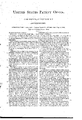
- Figure 1 is a side elevation of my improved laryngoscope.
- Fig. 2 is a sectional plan view of the light-chamber, taken on the line m a: of Fig. 1; and
- Fig. 3 is a perspective view of the removable shade.
- Fig. 4 is an elevation enlarged in size to show the mirror-arm with its adjustments.
- the light-chamber is composed of the cylinder A, ofsheet metal, which is provided with the downward extension I) and the upward extension a, which are fitted and secured in suitable openings formed in the material of the light chamber, the extension I) serving to admit the burner D into the center of the light-chamber, the extension a forming a passage immediately above the burner for the escape of the products of combustion from the burner.
- the concaved metallic reflector B In one end of the cylinder is placed the concaved metallic reflector B, and in the cylinder, near the other end thereof, is secured, by means of thethumb-screw d, the convex lens E, which concentrates and intensifies the rays of light from the burner.
- the concaved mirror G In front of the burner, upon the bent arm F,is placed the concaved mirror G, which reflects the intensified light from the burnerback into the mouth of the patient.
- This mirror isheld by the set-screw 6 upon the arm, and is fitted with ball-andsocket joints, so that it maybe adjusted to refleet the light to suit the different positions of the head of the patient while operations are being performed in different parts of the mouth.
- the arm F is externally screw-threaded at its rear end, and is secured upon'the top of the light-chamber by passing through the postf and screwing into a threaded perforation made in theextension a.
- h? represents the arm which connects the mirror with the rod F.
- Onthis arm is a sleeve, h having a threaded branch tube, [L3, through which worksthe clam p-screw h, and aside tube, 7L which slides on rod F, and may be held at i any desired point by the screw it, while the 1 distance of the mirror from the rod F may be regulated by sliding the rod in the sleeve k and clamping it at the desired point.
- h lt h represent the ball-and-socket joint connecting the rodwith the mirror, so that the latter may be placed at any desired angle.
- 7 1) represents a shade, which is placed on or within the forward end of the cylinder A, to shield the eyes of the operator from the reflected light which comes from the lens. This shade is provided with acollar, d, that abuts against an end collar, 61, of the cylinder A and works on the cylinder, so that it can be turned with the hand and held by friction in any desired position.
- the rod F and the shade D are correspondingly reversible, so that the operator can work on the right or left of the instrument.
- H represents a common mirror, which is also universally adjustable upon the rod F, .so that it may be set for reflecting light upon the bracket where the tools are placed, or so that the patient himself,or any person back of the chair, may see the operation performed.
- the head K of the stand J upon which the light-chamber is placed, is vertically adjustable, and is held at any desired point by means of the set-screw j, which passes through the sleeve j and impinges upon a rod or post of the stand, as will beclearly understood.
- the head K is formed of the two armsor supports 9 g, which reach up from the square enlargement 1", and are made integral therewith and with the sleevej, and upon the upper ends of these arms or supports is secured the rim I, which is formed with the flange i, as shown. This rim is of a size to just fit in the extension I), the loose edge thereof being adapted to rest upon flange i, as shown in Fig. 1, these parts hein g secured by the set-screws h h.
- the central tubeflc is the central tubeflc, upon which the burnerDis placed.
- This tube screws into the square enlargement i, and is intersected by the small short tube l, which also enters the square portion i, and upon which the pipe L is placed for conducting gas from an ordinary burner or other supply to the burner D.
- the stand is provided with the circular shelf or bracket N for holding the dentists tools.
- the dentist may use the instrument to advantage, he must not throw from the concave mirror a reflected light greater than about three and one-halfinches in diameter, so as to cover a space slightly larger than the patients mouth, and in order to do this the metallic reflector at the'rear end of cylinder must have a focus of about three inches.
- the focus of the piano-convex lens should be about five and one-fourth inches, and that of the concave mirror near the extreme end of rod F should be about nine inches.
- the plane mirror H is placed at the elbow of rod F for the convenience of the patient and for lighting thebracket where the tools are placed.
- the diameter of the main tube is made about four inches, and the distance from the lens to the concave mirror about eighteen inches, so as to' give the light an opportunity to cool before entering the patients mouth.
- the light-chamber In use the light-chamber is first to be raised five or six inches above the mouth of the pa tient, and the stand is to be placed upon the opposite side ot'the chair from that upon which the operator is to stand. The reflector is then to be arranged to throw the light from the light-chamber downward into the mouth of the patient, so that the tool used will not shade the tooth or pa'rtof the mouth to be operated in.
Landscapes
- Health & Medical Sciences (AREA)
- Life Sciences & Earth Sciences (AREA)
- Surgery (AREA)
- Nuclear Medicine, Radiotherapy & Molecular Imaging (AREA)
- Biomedical Technology (AREA)
- Optics & Photonics (AREA)
- Pathology (AREA)
- Radiology & Medical Imaging (AREA)
- Biophysics (AREA)
- Engineering & Computer Science (AREA)
- Physics & Mathematics (AREA)
- Heart & Thoracic Surgery (AREA)
- Medical Informatics (AREA)
- Molecular Biology (AREA)
- Animal Behavior & Ethology (AREA)
- General Health & Medical Sciences (AREA)
- Public Health (AREA)
- Veterinary Medicine (AREA)
- Endoscopes (AREA)
Description
N "STATES PATENT QFFICEO CARL BESELEB, on NEW YORK,'N. .Y.
LARYNGOSCOPE.
SPECIFICATION forming part of Letters Patent No; 257,646, dated May 9, 1882.
Application filed December 15, 18 81. (Modeh) To all whom it may concern:
Be it known that I, CARL BESELER, of the city, county, and State of New York, have invented a new and Improved Laryngoscope, of
which the following'is a full, clear, and exact description. a a i a a t This invention is especial] y adapted for dentists use for reflecting a strong light into the mouth of the patient during any operation upon the teeth; and the invention consists in the construction, combination, and arrangement of parts, as hereinafter fully described and claimed. a
Reference is to be had to the accompanying drawings, forming a part of this specification, in which similar letters of reference indicate corresponding parts in all the figures.
Figure 1 is a side elevation of my improved laryngoscope. Fig. 2 is a sectional plan view of the light-chamber, taken on the line m a: of Fig. 1; and Fig. 3 is a perspective view of the removable shade. Fig. 4 is an elevation enlarged in size to show the mirror-arm with its adjustments.
The light-chamber is composed of the cylinder A, ofsheet metal, which is provided with the downward extension I) and the upward extension a, which are fitted and secured in suitable openings formed in the material of the light chamber, the extension I) serving to admit the burner D into the center of the light-chamber, the extension a forming a passage immediately above the burner for the escape of the products of combustion from the burner. In one end of the cylinder is placed the concaved metallic reflector B, and in the cylinder, near the other end thereof, is secured, by means of thethumb-screw d, the convex lens E, which concentrates and intensifies the rays of light from the burner. In front of the burner, upon the bent arm F,is placed the concaved mirror G, which reflects the intensified light from the burnerback into the mouth of the patient. This mirror isheld by the set-screw 6 upon the arm, and is fitted with ball-andsocket joints, so that it maybe adjusted to refleet the light to suit the different positions of the head of the patient while operations are being performed in different parts of the mouth. The arm F is externally screw-threaded at its rear end, and is secured upon'the top of the light-chamber by passing through the postf and screwing into a threaded perforation made in theextension a.
h? represents the arm which connects the mirror with the rod F. Onthis arm is a sleeve, h having a threaded branch tube, [L3, through which worksthe clam p-screw h, and aside tube, 7L which slides on rod F, and may be held at i any desired point by the screw it, while the 1 distance of the mirror from the rod F may be regulated by sliding the rod in the sleeve k and clamping it at the desired point.
h lt h represent the ball-and-socket joint connecting the rodwith the mirror, so that the latter may be placed at any desired angle. 7 1) represents a shade, which is placed on or within the forward end of the cylinder A, to shield the eyes of the operator from the reflected light which comes from the lens. This shade is provided with acollar, d, that abuts against an end collar, 61, of the cylinder A and works on the cylinder, so that it can be turned with the hand and held by friction in any desired position. The rod F and the shade D are correspondingly reversible, so that the operator can work on the right or left of the instrument. a I
H represents a common mirror, which is also universally adjustable upon the rod F, .so that it may be set for reflecting light upon the bracket where the tools are placed, or so that the patient himself,or any person back of the chair, may see the operation performed.
The head K of the stand J, upon which the light-chamber is placed, is vertically adjustable, and is held at any desired point by means of the set-screw j, which passes through the sleeve j and impinges upon a rod or post of the stand, as will beclearly understood. The head K is formed of the two armsor supports 9 g, which reach up from the square enlargement 1", and are made integral therewith and with the sleevej, and upon the upper ends of these arms or supports is secured the rim I, which is formed with the flange i, as shown. This rim is of a size to just fit in the extension I), the loose edge thereof being adapted to rest upon flange i, as shown in Fig. 1, these parts hein g secured by the set-screws h h.
Between the arms orsupports gig is the central tubeflc, upon which the burnerDis placed. This tube It screws into the square enlargement i, and is intersected by the small short tube l, which also enters the square portion i, and upon which the pipe L is placed for conducting gas from an ordinary burner or other supply to the burner D.
The stand is provided with the circular shelf or bracket N for holding the dentists tools.
In order that the dentist may use the instrument to advantage, he must not throw from the concave mirror a reflected light greater than about three and one-halfinches in diameter, so as to cover a space slightly larger than the patients mouth, and in order to do this the metallic reflector at the'rear end of cylinder must have a focus of about three inches. The focus of the piano-convex lens should be about five and one-fourth inches, and that of the concave mirror near the extreme end of rod F should be about nine inches. The plane mirror H is placed at the elbow of rod F for the convenience of the patient and for lighting thebracket where the tools are placed. As the dental surgeon uses artificial light for several hours consecutively, the diameter of the main tube is made about four inches, and the distance from the lens to the concave mirror about eighteen inches, so as to' give the light an opportunity to cool before entering the patients mouth.
In use the light-chamber is first to be raised five or six inches above the mouth of the pa tient, and the stand is to be placed upon the opposite side ot'the chair from that upon which the operator is to stand. The reflector is then to be arranged to throw the light from the light-chamber downward into the mouth of the patient, so that the tool used will not shade the tooth or pa'rtof the mouth to be operated in.
It is better to have no other light in the room but that of the laryngoscope. It used in daylight, the shades of the window should be drawn.
A, and to be turned, raised, or lowered in the socket of a stand, as described.
2. The combination, with the cylinder A, having the upward extension at and a post, f, with a guide-aperture at the top, of the rod F, end-threaded to screw into a threaded perforation on said extension a, passing through the guide-aperture of post, and provided with a bend or elbow, whereby the mirrors may be held in their true relative position to the cylinder, whether the dentist works on the right or left of the instrument, as described.
3. Thecombination,withthecylinder A,ofthe shade D, swiveled on the end thereof and cut at an angle of about forty-five degrees, whereby it may be held by friction in any desired 7 position to protect the eyes of the operator from the light which comes from the lens, as described.
4. The combination, with the rod F and mirrors connected therewith by arms h, of the sleeves k having threaded branch tubes h, clamp-screws h, side tubes, [V5, with clampscrews h, and the ball-and-socket joint h h h whereby the mirrors G H may be adjusted with great nicety to each other and to the cylinder, as described.
CARL BESELER.
Witnesses:
H. A. West, 0. SEDGWIGK.
Publications (1)
| Publication Number | Publication Date |
|---|---|
| US257646A true US257646A (en) | 1882-05-09 |
Family
ID=2326931
Family Applications (1)
| Application Number | Title | Priority Date | Filing Date |
|---|---|---|---|
| US257646D Expired - Lifetime US257646A (en) | Carl beseler |
Country Status (1)
| Country | Link |
|---|---|
| US (1) | US257646A (en) |
Cited By (8)
| Publication number | Priority date | Publication date | Assignee | Title |
|---|---|---|---|---|
| US4995712A (en) * | 1989-03-28 | 1991-02-26 | Kei Mori | Light radiation stand |
| US8196872B1 (en) | 2009-12-16 | 2012-06-12 | Mcgrath Andrew H | Adjustable bracket assembly |
| US8302919B1 (en) | 2010-02-03 | 2012-11-06 | Mcgrath Andrew H | Adjustable bracket assembly |
| US8403430B2 (en) | 2011-02-07 | 2013-03-26 | Brass Smith, Llc | Adjustable food shield |
| US8936223B1 (en) | 2012-05-03 | 2015-01-20 | Andrew H. McGrath | Adjustable bracket assembly |
| USD756759S1 (en) | 2015-02-18 | 2016-05-24 | Brass Smith Llc | Support column for a food shield |
| US9782022B2 (en) | 2015-02-12 | 2017-10-10 | Brass Smith Llc | Adjustable food shield with detents |
| US10750887B2 (en) | 2013-06-18 | 2020-08-25 | Brass Smith Innovations, Llc | Food service equipment and systems |
-
0
- US US257646D patent/US257646A/en not_active Expired - Lifetime
Cited By (9)
| Publication number | Priority date | Publication date | Assignee | Title |
|---|---|---|---|---|
| US4995712A (en) * | 1989-03-28 | 1991-02-26 | Kei Mori | Light radiation stand |
| US8196872B1 (en) | 2009-12-16 | 2012-06-12 | Mcgrath Andrew H | Adjustable bracket assembly |
| US8302919B1 (en) | 2010-02-03 | 2012-11-06 | Mcgrath Andrew H | Adjustable bracket assembly |
| US8403430B2 (en) | 2011-02-07 | 2013-03-26 | Brass Smith, Llc | Adjustable food shield |
| US8585160B2 (en) | 2011-02-07 | 2013-11-19 | Brass Smith, LLC (BSI Designs) | Adjustable food shield |
| US8936223B1 (en) | 2012-05-03 | 2015-01-20 | Andrew H. McGrath | Adjustable bracket assembly |
| US10750887B2 (en) | 2013-06-18 | 2020-08-25 | Brass Smith Innovations, Llc | Food service equipment and systems |
| US9782022B2 (en) | 2015-02-12 | 2017-10-10 | Brass Smith Llc | Adjustable food shield with detents |
| USD756759S1 (en) | 2015-02-18 | 2016-05-24 | Brass Smith Llc | Support column for a food shield |
Similar Documents
| Publication | Publication Date | Title |
|---|---|---|
| US10247965B2 (en) | Ergonomic surgical loupes | |
| US257646A (en) | Carl beseler | |
| US5230622A (en) | Articulated mirror attachment for dental suction tips | |
| US6086228A (en) | Sterile illuminated magnifier and method for surgical use | |
| US1509041A (en) | Dental appliance | |
| US7217241B2 (en) | Device for orthodontic interventions | |
| US20100021863A1 (en) | Dental Retractor | |
| US5348470A (en) | Fiber-optic illuminated dental mirror | |
| US624392A (en) | Seaechroom | |
| US432614A (en) | Surgical apparatus | |
| US4538888A (en) | Binocular ophthalmoscope | |
| US20180303335A1 (en) | Shortened Slit Lamp Microscope | |
| US2459711A (en) | Dental unit | |
| US4637699A (en) | Binocular ophthalmoscope | |
| JPWO2015173851A1 (en) | Surgical light | |
| US4850688A (en) | Optical personal inpection instrument | |
| US2088735A (en) | Forehead lamp for doctors | |
| US1927181A (en) | Surgical light | |
| US1963279A (en) | Operating lamp | |
| US2633122A (en) | Ophthalmoscope | |
| US341873A (en) | Electric laryngoscope | |
| US281033A (en) | Laryngoscope | |
| Shetty et al. | Magnification-An endodontic review | |
| US370547A (en) | Dental illuminating apparatus | |
| US3462842A (en) | Dental sensing device |