US2576155A - Submarine compressional wave receptive apparatus - Google Patents
Submarine compressional wave receptive apparatus Download PDFInfo
- Publication number
- US2576155A US2576155A US657320A US65732046A US2576155A US 2576155 A US2576155 A US 2576155A US 657320 A US657320 A US 657320A US 65732046 A US65732046 A US 65732046A US 2576155 A US2576155 A US 2576155A
- Authority
- US
- United States
- Prior art keywords
- receptive
- dome
- submarine
- cable
- compressional wave
- Prior art date
- Legal status (The legal status is an assumption and is not a legal conclusion. Google has not performed a legal analysis and makes no representation as to the accuracy of the status listed.)
- Expired - Lifetime
Links
- 239000007799 cork Substances 0.000 description 15
- 239000004020 conductor Substances 0.000 description 10
- 229920001342 Bakelite® Polymers 0.000 description 9
- 239000004637 bakelite Substances 0.000 description 9
- 239000013078 crystal Substances 0.000 description 9
- 229920001971 elastomer Polymers 0.000 description 6
- 239000007788 liquid Substances 0.000 description 6
- 229910052751 metal Inorganic materials 0.000 description 5
- 239000002184 metal Substances 0.000 description 5
- 230000035939 shock Effects 0.000 description 5
- 230000033001 locomotion Effects 0.000 description 4
- XLYOFNOQVPJJNP-UHFFFAOYSA-N water Substances O XLYOFNOQVPJJNP-UHFFFAOYSA-N 0.000 description 4
- 239000003921 oil Substances 0.000 description 3
- 238000007792 addition Methods 0.000 description 2
- 238000010276 construction Methods 0.000 description 2
- 239000012530 fluid Substances 0.000 description 2
- 239000004033 plastic Substances 0.000 description 2
- 241000899771 Arenga undulatifolia Species 0.000 description 1
- 238000013459 approach Methods 0.000 description 1
- 239000004359 castor oil Substances 0.000 description 1
- 235000019438 castor oil Nutrition 0.000 description 1
- 238000004891 communication Methods 0.000 description 1
- 230000000694 effects Effects 0.000 description 1
- 239000004744 fabric Substances 0.000 description 1
- ZEMPKEQAKRGZGQ-XOQCFJPHSA-N glycerol triricinoleate Natural products CCCCCC[C@@H](O)CC=CCCCCCCCC(=O)OC[C@@H](COC(=O)CCCCCCCC=CC[C@@H](O)CCCCCC)OC(=O)CCCCCCCC=CC[C@H](O)CCCCCC ZEMPKEQAKRGZGQ-XOQCFJPHSA-N 0.000 description 1
- 239000004816 latex Substances 0.000 description 1
- 229920000126 latex Polymers 0.000 description 1
- 239000013521 mastic Substances 0.000 description 1
- 238000005259 measurement Methods 0.000 description 1
- 238000000034 method Methods 0.000 description 1
- 239000000203 mixture Substances 0.000 description 1
- 230000007935 neutral effect Effects 0.000 description 1
- ISWSIDIOOBJBQZ-UHFFFAOYSA-N phenol group Chemical group C1(=CC=CC=C1)O ISWSIDIOOBJBQZ-UHFFFAOYSA-N 0.000 description 1
- 239000013535 sea water Substances 0.000 description 1
- 229910052709 silver Inorganic materials 0.000 description 1
- 239000004332 silver Substances 0.000 description 1
- 239000000126 substance Substances 0.000 description 1
- 239000000725 suspension Substances 0.000 description 1
- 239000002023 wood Substances 0.000 description 1
Images

Classifications
-
- B—PERFORMING OPERATIONS; TRANSPORTING
- B06—GENERATING OR TRANSMITTING MECHANICAL VIBRATIONS IN GENERAL
- B06B—METHODS OR APPARATUS FOR GENERATING OR TRANSMITTING MECHANICAL VIBRATIONS OF INFRASONIC, SONIC, OR ULTRASONIC FREQUENCY, e.g. FOR PERFORMING MECHANICAL WORK IN GENERAL
- B06B1/00—Methods or apparatus for generating mechanical vibrations of infrasonic, sonic, or ultrasonic frequency
- B06B1/02—Methods or apparatus for generating mechanical vibrations of infrasonic, sonic, or ultrasonic frequency making use of electrical energy
- B06B1/06—Methods or apparatus for generating mechanical vibrations of infrasonic, sonic, or ultrasonic frequency making use of electrical energy operating with piezoelectric effect or with electrostriction
- B06B1/0607—Methods or apparatus for generating mechanical vibrations of infrasonic, sonic, or ultrasonic frequency making use of electrical energy operating with piezoelectric effect or with electrostriction using multiple elements
- B06B1/0622—Methods or apparatus for generating mechanical vibrations of infrasonic, sonic, or ultrasonic frequency making use of electrical energy operating with piezoelectric effect or with electrostriction using multiple elements on one surface
- B06B1/0629—Square array
-
- B—PERFORMING OPERATIONS; TRANSPORTING
- B06—GENERATING OR TRANSMITTING MECHANICAL VIBRATIONS IN GENERAL
- B06B—METHODS OR APPARATUS FOR GENERATING OR TRANSMITTING MECHANICAL VIBRATIONS OF INFRASONIC, SONIC, OR ULTRASONIC FREQUENCY, e.g. FOR PERFORMING MECHANICAL WORK IN GENERAL
- B06B1/00—Methods or apparatus for generating mechanical vibrations of infrasonic, sonic, or ultrasonic frequency
- B06B1/02—Methods or apparatus for generating mechanical vibrations of infrasonic, sonic, or ultrasonic frequency making use of electrical energy
- B06B1/06—Methods or apparatus for generating mechanical vibrations of infrasonic, sonic, or ultrasonic frequency making use of electrical energy operating with piezoelectric effect or with electrostriction
- B06B1/0644—Methods or apparatus for generating mechanical vibrations of infrasonic, sonic, or ultrasonic frequency making use of electrical energy operating with piezoelectric effect or with electrostriction using a single piezoelectric element
- B06B1/0662—Methods or apparatus for generating mechanical vibrations of infrasonic, sonic, or ultrasonic frequency making use of electrical energy operating with piezoelectric effect or with electrostriction using a single piezoelectric element with an electrode on the sensitive surface
- B06B1/0681—Methods or apparatus for generating mechanical vibrations of infrasonic, sonic, or ultrasonic frequency making use of electrical energy operating with piezoelectric effect or with electrostriction using a single piezoelectric element with an electrode on the sensitive surface and a damping structure
Definitions
- Objects of the invention are to provide direetive receiving apparatus for use in compressional wave systems which will maintain a vertical beam axis under all conditions, and which will be rugged and simple of construction, so that it may be committed to the water with severe shock and yet preserve its receptive properties for long periods of time.
- submarine compressional wave receptive apparatus which will maintain a" vertical beam axis.
- such apparatus may be disposed in the approaches to a water lock.
- the speed of a vessel approachin the lock can be automatically taken into account from the information provided by the responses from the receptive apparatus; and the lock may be opened at the proper time; It is easily seen that in such a case, the information given by the receptive apparatus must be accurate under all conditions.
- Another example may arise in connection with operations for detecting sources of compressional wave disturbances. If an area of the sea can be quickly covered with transducers, it can be determined with a satisfactory degree of certi tude whether or not a source of compressional wave disturbances is present, and if so, movements of this source can be followed with facility.
- data gleaned from measurements of various compressional Wave disturbances by the receptive apparatus of the invention will indicate the nature of the source. The coverage of a lar'gearea of sea in a short time may be accomplished by droppingsuch receptive aping and highly shock-resistant.
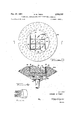
- Fig. 2 is a section on line 2"-'2 of Fig. 1, on a smaller scale; 7
- Fig. 3 shows a race View or the transducer of theen'ibodirneiitof'F'ig'iires land 2, and
- Fig. 4 snows a cutaway side View of the same transducer.
- Fig. 5 is an enlarged fragmentary view showmg s'triitii-r' of the mastic came"
- the elements of an rribodieririt of theiriViition are ilhis'tratd in Figure '1. These are an array of piezoelectric elements forming an elec troaccusuc transducer 10, a flexible "able n susg pending the iiiou'ritin'g of the transduc'er'm; and a rubber donie l2 filled with Castor oil or other the construction of this cablethe conductors. are formed spirally and "then are dipped in latex, the ensuing com ination be'fiiig eitreiiiely elast'ic';
- the leads it ll and H32 are brought out from cable ll throughan' opening near the bottom of Bakelite tube late terminals I93 and J0 0n terminal board Hi5.
- the terminal board l05. is;;- mounted can-s plate l9, which in this embodiment may be vise Flexible cable It ualiz'ed as a part of a side plate of a water tight box or enclosure 50 containing an electronic amplifier 200, and associated gear.
- the terminals I03 and I04 and a neutral terminal I06 on the board serve as binding posts for the conductors of output cable I1 which passes through frame plate I9, in going to electronic amplifier 200.
- This cable is shown in a position elevated from its normal.
- a screw 23 plugs an opening in the plate I9 through which oil may be introduced and evacuated from the dome I2.
- the rubber dome I2 is molded to a metal ring 25. Bolts 26 and nuts 21, regularly spaced around the ring, secure the dome to the frame plate I9.
- FIG 2 is shown a top view of the same embodiment in which a part of the dome I2 is cut away to bring the interior into evidence.
- the metal ring 25 surrounds the cutaway part of the dome, and the tops of bolts 26 and nuts 21 are seen to be regularly spaced around the ring 25.
- Elastic cable II issues from the top of the Bakelite tube I3, which is seen to be located centrally in respect to the base plate and rubber dome.
- the conductors IOI and I02 are depicted issuing from the flexible cable. II which protrudes from Bakelite tube I 3 near its bottom.
- the conductors IN and I02 are fastened to terminals I03, I04 on the Bakelite terminal strip I05. Two of the conductors of output cable I?
- Figure 3 depicts a face view of the piezoelectric transducer I0 mounted in a truncated biconically shaped cork mounting 300.
- the cork mounting 300 is of sufficient size as to easily float the combination; the dimensions must be such that it must not touch the sides of the dome or base plate in its possible motions and at the same time its geometrical center must be close to the geometrical center of the dome, as illustrated in Figure 1.
- a square array of nine crystals 30 is shown in Figure 3.
- U-shaped electrodes 32 in contact with crystals 30 place these crystals in effective parallel connection. Each electrode 32 is in contact with half the side area of the crystals.
- the respective electrodes 32 are connected within the cork mounting 300 to conductors IOI and I02 as shown in the section view of Figure 4.
- FIG. 4 shows flexible cable II entering the biconical cork mounting 300.
- the flexible cable II has a knob III) molded at its upper end.
- the cable is put through the side of the cork mounting 300 in the space 30I which is filled with a rubber chemical composition, not shown in thefigure, at the end of the process, and pulled through the-hole at the bottom of the cork mounting 300.
- leads II" and I02 extending beyond the knob IIO are cleaned of illsulation for a short length III and H2 so that the conductors are exposed, and then this ex posed conductor section is wound spirally backand forth around the further insulated sectionof the leads IM and I02. This is to provide added resistance to shock. Since the conductors may be of very fine wire, such added precaution is necessary.
- Leads WI and I02 are then brought through the guide holes filled in the cork body, and soldered to their respective electrodes. The transducer is then inserted in the cork mounting. The crystals 30 are seen to be cemented to a plastic backing member 3!. Bakelite insulating strips 35 are added around the entire transducer proper and cemented to the cork mounting.
- the plastic backing member 3I fits under the Bakelite strip so that when these are cemented to the cork mounting the transducer is secured.
- the cork mounting reflects acoustic energy well because of its acoustic impedance.
- a Bakelite top plate 36 fits into a slight depression in the flat face of the cork mounting and is cemented therein, making the cork mounting 300 into the geometrical shape of a truncated cone.
- the viscosity of the liquid medium in which the transducer freely floats prevents the flexible elastic cord from wrapping around the Bakelite tube due to movements of the box or enclosure on which the housing is mounted.
- the action of the viscous medium will generally substantially dissipate the effect of any disturbances. Owing to the degrees of freedom provided by the elastic cable suspension in the liquid medium the transducer will always regain its receptive properties despite the shock of entering the water or shock arising from severe compressional disturbances, and despite motions of the box or enclosure on which the apparatus may be mounted.
- a receptive apparatus for submarine compressional waves comprising a base plate, a dome mounted on the base plate to form with the plate a fluid tight chamber, a body of liquid contained in the chamber formed by the dome and plate, a supporting tube mounted on the base plate within the chamber and extending from near the center of the plate to near the center of the chamber, a cork imbedded-directional hydrophone situated in the chamber and an elastic flexible cable extending through the supporting tube to the cork-imbedded hydrophone and constituting the sole support therefor, the length of cable extending from the unmounted end of the tube to the hydrophone and the overall size of the cork embedded-hydrophone being limited to prevent contact of the hydrophone with the dome, whereby the hydrophone is floated upwardly from the unmounted end of the supporting tube in various positionsof the dome and base plate without contacting the dome.
Landscapes
- Engineering & Computer Science (AREA)
- Mechanical Engineering (AREA)
- Transducers For Ultrasonic Waves (AREA)
Description
SUBMARINE COMPR-ESSIONAL WAVE RECEPTIVE APPARATUS Filed March 26, 1946 2 Sl-IEETSSHEET l Nov. 27, 1951 H. M. TRENT 2,576,155
SUBMARINE COMPRESSIONAL WAVE RECEPTIVE APPARATUS Filed March 26, 1946 2 SHEETSSHEET 2 HORACE M. TRENT Patented Nov. 2 7, 1951 UNITED STAT SUBMARINE COMPRESSIONAL WAVE RECEPTIVE APPARATUS V Horace Trent, Alexandria, Va. Application March 26, 1946, Serial No: 657,32 2 Claims. (01. 1i7 3') (Granted under the act of March 8, iscaas amended April 30, 1928; 370 O; G: 757) This invention relates to receiving apparatus for submarine compressional waves. It has ar ticular application to a directional receivin apparatus which will maintain a single orientation of beam pattern in space.
Objects of the invention are to provide direetive receiving apparatus for use in compressional wave systems which will maintain a vertical beam axis under all conditions, and which will be rugged and simple of construction, so that it may be committed to the water with severe shock and yet preserve its receptive properties for long periods of time.
Features of the invention are the correlation of the directional receptive properties of an ar-' ray of piezoelectric crystals with the verticalseeking property of a fioatable mounting for the array, the use of a rubber housing mounted on a frame plate and containing an oil-like liquid to' provide acoustic communication and an impedance match between the sea water and the crystals, and the use of a flexible and stretchable cable to suspend the array with two degrees of rotational freedom and one degree of elastic freedom.
In a number of recent applications, it has been found desirable to have submarine compressional wave receptive apparatus which will maintain a" vertical beam axis. For example, such apparatus may be disposed in the approaches to a water lock. The speed of a vessel approachin the lock can be automatically taken into account from the information provided by the responses from the receptive apparatus; and the lock may be opened at the proper time; It is easily seen that in such a case, the information given by the receptive apparatus must be accurate under all conditions.
Another example may arise in connection with operations for detecting sources of compressional wave disturbances. If an area of the sea can be quickly covered with transducers, it can be determined with a satisfactory degree of certi tude whether or not a source of compressional wave disturbances is present, and if so, movements of this source can be followed with facility. In addition, data gleaned from measurements of various compressional Wave disturbances by the receptive apparatus of the invention will indicate the nature of the source. The coverage of a lar'gearea of sea in a short time may be accomplished by droppingsuch receptive aping and highly shock-resistant.
As will appear hereinunder', it has been found entirely practicable in this invention to con struct receptive apparatus for use with subma rine compressional wave systems which win meet the requirements pointed out above. In addi tion, the invention provides for the cooperative use of electronic amplifiers and other devices; 7
The principles of this invention will be more readny understood from the following detailed "description and (11 Wings", of whichf Figure 1 is a section throng'lithecenter' of an embodiment of the invention which is attached to the top side are water-tight box or enclosure which cdritams. electronic and other associated apparatus; v
Fig. 2 is a section on line 2"-'2 of Fig. 1, on a smaller scale; 7
Fig. 3 shows a race View or the transducer of theen'ibodirneiitof'F'ig'iires land 2, and
Fig. 4 snows a cutaway side View of the same transducer.
Fig. 5 is an enlarged fragmentary view showmg s'triitii-r' of the mastic came";
The elements of an rribodiriirit of theiriViition are ilhis'tratd in Figure '1. These are an array of piezoelectric elements forming an elec troaccusuc transducer 10, a flexible "able n susg pending the iiiou'ritin'g of the transduc'er'm; and a rubber donie l2 filled with Castor oil or other the construction of this cablethe conductors. are formed spirally and "then are dipped in latex, the ensuing com ination be'fiiig eitreiiiely elast'ic';
well as serving to insulate one condense frorr'i fouling, and long enough to permit rotational freedom of the transducer. The leads it ll and H32 are brought out from cable ll throughan' opening near the bottom of Bakelite tube late terminals I93 and J0 0n terminal board Hi5. The terminal board l05.is;;- mounted can-s plate l9, which in this embodiment may be vise Flexible cable It ualiz'ed as a part of a side plate of a water tight box or enclosure 50 containing an electronic amplifier 200, and associated gear. The terminals I03 and I04 and a neutral terminal I06 on the board serve as binding posts for the conductors of output cable I1 which passes through frame plate I9, in going to electronic amplifier 200. This cable is shown in a position elevated from its normal. A rubber gasket 29, a metal washer 20 and a larger washer 2|, secured to the metal plate I9 by means of four screws 22, forms an oil-tight seal through which output cable Il may pass without having the oil or other liquid seep into the interior of the enclosure 50 containing electronic amplifier 200. A screw 23 plugs an opening in the plate I9 through which oil may be introduced and evacuated from the dome I2. The rubber dome I2 is molded to a metal ring 25. Bolts 26 and nuts 21, regularly spaced around the ring, secure the dome to the frame plate I9.
In Figure 2 is shown a top view of the same embodiment in which a part of the dome I2 is cut away to bring the interior into evidence. The metal ring 25 surrounds the cutaway part of the dome, and the tops of bolts 26 and nuts 21 are seen to be regularly spaced around the ring 25. Elastic cable II issues from the top of the Bakelite tube I3, which is seen to be located centrally in respect to the base plate and rubber dome. The conductors IOI and I02 are depicted issuing from the flexible cable. II which protrudes from Bakelite tube I 3 near its bottom. The conductors IN and I02 are fastened to terminals I03, I04 on the Bakelite terminal strip I05. Two of the conductors of output cable I? are arranged to be fastened on the same terminals, (with the addition of a single conductor fastened to a ground terminal), and the output cable I1 is fixed in a special position relatively to the terminal board I by means of a clamp 28. In Figure 1 the output cable is shown unclamped and elevated for purposes of illustration.
Figure 3 depicts a face view of the piezoelectric transducer I0 mounted in a truncated biconically shaped cork mounting 300. The cork mounting 300 is of sufficient size as to easily float the combination; the dimensions must be such that it must not touch the sides of the dome or base plate in its possible motions and at the same time its geometrical center must be close to the geometrical center of the dome, as illustrated in Figure 1. A square array of nine crystals 30 is shown in Figure 3. U-shaped electrodes 32 in contact with crystals 30 place these crystals in effective parallel connection. Each electrode 32 is in contact with half the side area of the crystals. The respective electrodes 32 are connected within the cork mounting 300 to conductors IOI and I02 as shown in the section view of Figure 4. The other sides of the crystals are insulated from each other by means of Bakelite, impregnated cloth or phenolic strips 34. The electrodes 32 may be of thin silver or other suitable metal, and the crystal side in contact with the electrode may be silvered or tinned in any well-known manner. Figure 4 shows flexible cable II entering the biconical cork mounting 300. When it is formed, the flexible cable II has a knob III) molded at its upper end. In assembling the transducer and mounting, the cable is put through the side of the cork mounting 300 in the space 30I which is filled with a rubber chemical composition, not shown in thefigure, at the end of the process, and pulled through the-hole at the bottom of the cork mounting 300. The leads II" and I02 extending beyond the knob IIO are cleaned of illsulation for a short length III and H2 so that the conductors are exposed, and then this ex posed conductor section is wound spirally backand forth around the further insulated sectionof the leads IM and I02. This is to provide added resistance to shock. Since the conductors may be of very fine wire, such added precaution is necessary. Leads WI and I02 are then brought through the guide holes filled in the cork body, and soldered to their respective electrodes. The transducer is then inserted in the cork mounting. The crystals 30 are seen to be cemented to a plastic backing member 3!. Bakelite insulating strips 35 are added around the entire transducer proper and cemented to the cork mounting. The plastic backing member 3I fits under the Bakelite strip so that when these are cemented to the cork mounting the transducer is secured. The cork mounting reflects acoustic energy well because of its acoustic impedance. A Bakelite top plate 36, of suitable dimensions, fits into a slight depression in the flat face of the cork mounting and is cemented therein, making the cork mounting 300 into the geometrical shape of a truncated cone.
The viscosity of the liquid medium in which the transducer freely floats prevents the flexible elastic cord from wrapping around the Bakelite tube due to movements of the box or enclosure on which the housing is mounted. The action of the viscous medium will generally substantially dissipate the effect of any disturbances. Owing to the degrees of freedom provided by the elastic cable suspension in the liquid medium the transducer will always regain its receptive properties despite the shock of entering the water or shock arising from severe compressional disturbances, and despite motions of the box or enclosure on which the apparatus may be mounted.
No attempt has here been made to exhaustively cover or point out all applications of the invention. Numerous features and applications other than those pointed out will be apparent to those skilled in the art. The scope of the invention is to be defined in the following claims.
The invention described herein may be manufactured and used by or for the Government of the United States of America for governmental purposes without the payment of any royalty thereon or therefor.
What is claimed is:
1. A receptive apparatus for submarine compressional waves comprising a base plate, a dome mounted on the base plate to form with the plate a fluid tight chamber, a body of liquid contained in the chamber formed by the dome and plate, a supporting tube mounted on the base plate within the chamber and extending from near the center of the plate to near the center of the chamber, a cork imbedded-directional hydrophone situated in the chamber and an elastic flexible cable extending through the supporting tube to the cork-imbedded hydrophone and constituting the sole support therefor, the length of cable extending from the unmounted end of the tube to the hydrophone and the overall size of the cork embedded-hydrophone being limited to prevent contact of the hydrophone with the dome, whereby the hydrophone is floated upwardly from the unmounted end of the supporting tube in various positionsof the dome and base plate without contacting the dome.
5 ispherical fluid tight dome element, a body of liquid filling the interior of said dome, an oil floatable hydrophone assembly, an elastic flexible circuit cable for the hydrophone, a cable supporting member within the dome fixed relative to the dome, said cable being held by the supporting member at substantially the geometric center of the dome and constituting the sole support means between the supporting member and the hydrophone assembly.
HORACE M. TRENT.
REFERENCES CITED The following references are of record in the file of this patent:
Number Number 6 UNITED STATES PATENTS Name Date Sawyer Nov. 1'7 ,1896 Wood et a1 Dec. 20, 1921 Williams Oct. 18, 1932 Kunze Nov. 5, 1935 Canon et a1 Feb. 2, 1943 Williams Sept. 1'7, 1946 Benioff Feb. 11, 1947 Massa Feb. 1 1, 1950 Massa Sept. 5, 1950 FOREIGN PATENTS Country Date Great Britain Mar. 6, 1919
Priority Applications (1)
| Application Number | Priority Date | Filing Date | Title |
|---|---|---|---|
| US657320A US2576155A (en) | 1946-03-26 | 1946-03-26 | Submarine compressional wave receptive apparatus |
Applications Claiming Priority (1)
| Application Number | Priority Date | Filing Date | Title |
|---|---|---|---|
| US657320A US2576155A (en) | 1946-03-26 | 1946-03-26 | Submarine compressional wave receptive apparatus |
Publications (1)
| Publication Number | Publication Date |
|---|---|
| US2576155A true US2576155A (en) | 1951-11-27 |
Family
ID=24636672
Family Applications (1)
| Application Number | Title | Priority Date | Filing Date |
|---|---|---|---|
| US657320A Expired - Lifetime US2576155A (en) | 1946-03-26 | 1946-03-26 | Submarine compressional wave receptive apparatus |
Country Status (1)
| Country | Link |
|---|---|
| US (1) | US2576155A (en) |
Cited By (8)
| Publication number | Priority date | Publication date | Assignee | Title |
|---|---|---|---|---|
| US2783449A (en) * | 1953-08-28 | 1957-02-26 | Texas Co | Seismic velocity measurement |
| DE1016611B (en) * | 1954-12-13 | 1957-09-26 | Electroacustic Gmbh | Echosounder device with a display device with visual reading of the measured values, preferably a cathode ray tube |
| US2875352A (en) * | 1953-03-04 | 1959-02-24 | Gulton Ind Inc | Blast gauge |
| US3002179A (en) * | 1952-09-03 | 1961-09-26 | Donald W Kuester | Low frequency hydrophone |
| US3048815A (en) * | 1952-11-05 | 1962-08-07 | Edward G Thurston | Low frequency transducer |
| DE1158881B (en) * | 1959-07-10 | 1963-12-05 | Phil Nat Siegfried Fahrentholz | Device and method for echo sounding, in particular for purposes of deep sea research |
| DE977439C (en) * | 1955-08-05 | 1966-06-08 | Electroacustic Ges M B H | Floating plumb bob |
| US4899845A (en) * | 1987-12-11 | 1990-02-13 | Consiglio Nazionale Delle Ricerche | Echographic technique-based method and apparatus to detect structure and anomalies of the subsoil and/or sea bottom and the like |
Citations (10)
| Publication number | Priority date | Publication date | Assignee | Title |
|---|---|---|---|---|
| US571539A (en) * | 1896-11-17 | Island | ||
| GB191503695A (en) * | 1915-03-08 | 1916-06-08 | Charles James Richardson | Improvements in Relief Valves. |
| US1401024A (en) * | 1917-11-12 | 1921-12-20 | Submarine Signal Co | Diaphragm-mounting |
| US1883433A (en) * | 1927-09-12 | 1932-10-18 | Submarine Signal Corp | System and apparatus for submarine signaling |
| US2019497A (en) * | 1933-05-29 | 1935-11-05 | Submarine Signal Co | Acoustic echo distance measuring system |
| US2310017A (en) * | 1941-05-05 | 1943-02-02 | Wells Gardner & Co | Emergency transmitter |
| US2407697A (en) * | 1935-09-14 | 1946-09-17 | Submarine Signal Co | Apparatus for submarine signaling |
| US2415407A (en) * | 1942-12-09 | 1947-02-11 | Submarine Signal Co | Submarine signaling apparatus |
| US2497680A (en) * | 1942-03-26 | 1950-02-14 | Brush Dev Co | Piezoelectric crystal unit |
| US2521642A (en) * | 1945-11-29 | 1950-09-05 | Brush Dev Co | Transducer means |
-
1946
- 1946-03-26 US US657320A patent/US2576155A/en not_active Expired - Lifetime
Patent Citations (10)
| Publication number | Priority date | Publication date | Assignee | Title |
|---|---|---|---|---|
| US571539A (en) * | 1896-11-17 | Island | ||
| GB191503695A (en) * | 1915-03-08 | 1916-06-08 | Charles James Richardson | Improvements in Relief Valves. |
| US1401024A (en) * | 1917-11-12 | 1921-12-20 | Submarine Signal Co | Diaphragm-mounting |
| US1883433A (en) * | 1927-09-12 | 1932-10-18 | Submarine Signal Corp | System and apparatus for submarine signaling |
| US2019497A (en) * | 1933-05-29 | 1935-11-05 | Submarine Signal Co | Acoustic echo distance measuring system |
| US2407697A (en) * | 1935-09-14 | 1946-09-17 | Submarine Signal Co | Apparatus for submarine signaling |
| US2310017A (en) * | 1941-05-05 | 1943-02-02 | Wells Gardner & Co | Emergency transmitter |
| US2497680A (en) * | 1942-03-26 | 1950-02-14 | Brush Dev Co | Piezoelectric crystal unit |
| US2415407A (en) * | 1942-12-09 | 1947-02-11 | Submarine Signal Co | Submarine signaling apparatus |
| US2521642A (en) * | 1945-11-29 | 1950-09-05 | Brush Dev Co | Transducer means |
Cited By (8)
| Publication number | Priority date | Publication date | Assignee | Title |
|---|---|---|---|---|
| US3002179A (en) * | 1952-09-03 | 1961-09-26 | Donald W Kuester | Low frequency hydrophone |
| US3048815A (en) * | 1952-11-05 | 1962-08-07 | Edward G Thurston | Low frequency transducer |
| US2875352A (en) * | 1953-03-04 | 1959-02-24 | Gulton Ind Inc | Blast gauge |
| US2783449A (en) * | 1953-08-28 | 1957-02-26 | Texas Co | Seismic velocity measurement |
| DE1016611B (en) * | 1954-12-13 | 1957-09-26 | Electroacustic Gmbh | Echosounder device with a display device with visual reading of the measured values, preferably a cathode ray tube |
| DE977439C (en) * | 1955-08-05 | 1966-06-08 | Electroacustic Ges M B H | Floating plumb bob |
| DE1158881B (en) * | 1959-07-10 | 1963-12-05 | Phil Nat Siegfried Fahrentholz | Device and method for echo sounding, in particular for purposes of deep sea research |
| US4899845A (en) * | 1987-12-11 | 1990-02-13 | Consiglio Nazionale Delle Ricerche | Echographic technique-based method and apparatus to detect structure and anomalies of the subsoil and/or sea bottom and the like |
Similar Documents
| Publication | Publication Date | Title |
|---|---|---|
| US3187300A (en) | Pressure-compensated transducer | |
| US4733379A (en) | Line array transducer assembly | |
| US4345473A (en) | Vertical component accelerometer | |
| US2384465A (en) | Submarine signaling appabatus | |
| US3970878A (en) | Piezoelectric transducer unit and hydrophone assembly | |
| CA1134939A (en) | Polymeric piezoelectric microprobe having a damper | |
| CA1264371A (en) | Flexible piezoelectric transducer assembly | |
| US4166229A (en) | Piezoelectric polymer membrane stress gage | |
| US3718898A (en) | Transducer | |
| US4004266A (en) | Transducer array having low cross-coupling | |
| US4536862A (en) | Seismic cable assembly having improved transducers | |
| US2576155A (en) | Submarine compressional wave receptive apparatus | |
| US4864179A (en) | Two-dimensional piezoelectric transducer assembly | |
| US1345717A (en) | Acoustic device | |
| US2923916A (en) | woodworth | |
| US2416314A (en) | Electroacoustic transducer | |
| US3277436A (en) | Hollow electro-acoustic transducer | |
| US2939106A (en) | High frequency electromechanical transducer | |
| US2413462A (en) | Transducer | |
| US2797399A (en) | Underwater transducer | |
| US6275448B1 (en) | Pressure-compensated acceleration-insensitive hydrophone | |
| US3113288A (en) | Supersensitive shielded crystal hydrophone | |
| US3286227A (en) | Line hydrophone | |
| US4926397A (en) | Depth alarm for a seismic sensor | |
| US3054982A (en) | Hydrostatic pressure transducer |