US257585A - hobbs - Google Patents
hobbs Download PDFInfo
- Publication number
- US257585A US257585A US257585DA US257585A US 257585 A US257585 A US 257585A US 257585D A US257585D A US 257585DA US 257585 A US257585 A US 257585A
- Authority
- US
- United States
- Prior art keywords
- bullet
- bullets
- patching
- disk
- periphery
- Prior art date
- Legal status (The legal status is an assumption and is not a legal conclusion. Google has not performed a legal analysis and makes no representation as to the accuracy of the status listed.)
- Expired - Lifetime
Links
- 230000033001 locomotion Effects 0.000 description 7
- 238000002788 crimping Methods 0.000 description 3
- 230000008933 bodily movement Effects 0.000 description 2
- 238000009963 fulling Methods 0.000 description 2
- 230000000284 resting effect Effects 0.000 description 2
- 206010001052 Acute respiratory distress syndrome Diseases 0.000 description 1
- 229920000715 Mucilage Polymers 0.000 description 1
- 239000000853 adhesive Substances 0.000 description 1
- 201000000028 adult respiratory distress syndrome Diseases 0.000 description 1
- 229940090045 cartridge Drugs 0.000 description 1
- 238000010276 construction Methods 0.000 description 1
- 238000000151 deposition Methods 0.000 description 1
- 230000000694 effects Effects 0.000 description 1
- 230000002452 interceptive effect Effects 0.000 description 1
- 230000001105 regulatory effect Effects 0.000 description 1
- 230000000630 rising effect Effects 0.000 description 1
- 238000005096 rolling process Methods 0.000 description 1
Images


Classifications
-
- F—MECHANICAL ENGINEERING; LIGHTING; HEATING; WEAPONS; BLASTING
- F42—AMMUNITION; BLASTING
- F42B—EXPLOSIVE CHARGES, e.g. FOR BLASTING, FIREWORKS, AMMUNITION
- F42B10/00—Means for influencing, e.g. improving, the aerodynamic properties of projectiles or missiles; Arrangements on projectiles or missiles for stabilising, steering, range-reducing, range-increasing or fall-retarding
Definitions
- the first part of our invention includes the automatic feeding of bullets into the recesses in the periphery of the continuously-rotating patching-machine disk, which we accomplish by imparting to each bullet while standing upright upon its base a sidewise bodily movement in a path bisecting the circle de- 2 5 scribed by the periphery of the patchingmachine disk.
- the direction and velocity of this movement are such as to carry the bullet progressively forward with the recess which it is to occupy, and at the same time move the 0 bullet radially inward, and thus deposit it in the bottom of the recess, after which the further progress of the bullet is efi'ected by the rotation of the patching-machine disk.
- Our invention alsoincludes certainimprove 3 5 ments of the bullet-patching machine.
- ⁇ Ve construct the magazine with a yielding side wall, which bears with an elastic pressure upon the tail ends of the massed slips of paper.
- a reciprocating bar for tucking a portion of the projecting patch under the base of the 4 5 bullet preparatory to the crimping operation;
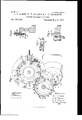
- Figure 1 is a top view of a patching-machine provided with our improvements.
- Fig. 2 is a vertical section through the line 8 s on Fig. 1, showing the groove in the face of the transferwheel, which admits the end of the stationary cam for forcing the bullets radially outward from the transfer-wheel.
- Fig. 3 is a vertical section upon an enlarged scale, taken through the radial line if t on Fig. 1, showing a portion of the top guide for the bullets and an adjusting-screw for regulating the position thereof.
- Fig. 4 is a vertical section, also upon an enlarged scale, taken through the radial line a n on Fig.
- FIG. 5 is a top view of the magazine containing the paper slips, showing a portion of the patching-machine disk and a bullet about to be rolled across the face of the magazine.
- Fig. 6 is avertical section through the line v n on Fig. 5.
- Fig. 7 is avertical section through the line 20 w on Fig. Fig. 8is a vertical section, through the line 00 a; on Fig. 1, of a reciprocating tuckerand mechanism for operating it.
- Fig. 9 is a horizontal section through the line'y y on Fig. 8.
- Fig. 10 is a horizontal section through the linezzon Fig. 8. So
- the drawings show a friction-dial, A, of the 5 ordinary construction, excepting that the end section, a, of the outermost of the two curved stationary guide-walls A and A is made capable of yielding in a horizontal plane outward from the dial A by being provided with too gle column and pushed successively outward against the periphery of our transfer-wheel B, provided with the hooks or ratchet-teeth b.
- each of the teeth I is circularly recessed to enable it to partially embrace a bullet resting upright upon its base, and the periphery of the transfer-wheel from the inner edge of the recess b to the apex b of the next preceding tooth presents the convex bearing b so that this part of the transfer-wheel gradually diminishes in radius, and hence affords aconstant support for the bullet while the latter is being gradually pushed outward from between the guide-walls A and A It is usual to make one or both of the guidewalls A and A vibratory; but as this is well known and forms no part of ourinvention, we have not deemed it necessary to show the vibratingmechanism.
- Thetransfer-wheelB has the circumferential groove 0 formed in itsperiphery, and is surrounded by the curved guardwall B, which is secured to the stationary table B immediately beneath the transferwheel.
- the bullets caught by the teeth I) are successively swept away from the end of the column of bullets presented by the frictiondial.
- the movable end section, a, of the outer guide-wall yields, if necessary, to permit the lateral sidewise movement of the end bullet, and in yielding presses upon and forces the bullet toward the periphery of the transferwheel, and thus acts to fully seat the bullet in the recessed face of the tooth b.
- the bullets are carried around in the arc of a circle, and are prevented from tipping over partly by means of the guard-wall B and partly by means of the light springs B the free ends of which project respectively through horizontal slots B in the eurved'guard-wall, and bear against the bodies of the bullets as they are carried around by the teeth of the transfer-wheel.
- the end portions, B and B, of tlieguarch wall B may be made flexible and arranged to springtoward the periphery of the transferwheel, so as to yield in an outward direction as the bullets are carried along theirinner faces.
- the transfer wheel is arranged in the same horizontal plane as the continuously-rotating patching-machine disk D, and is so geared thereto that its periphery and the periphery of the patching machine disk move with like speed, the transfer-wheel rotating in one direction and the patching-machine disk rotating in the opposite direction.
- the stationary tangential cam c the face of which forms a part of a right line bisecting the peripheries of the trausfer-wh eel and the patchin g-m achine disk.
- the end dot the cam 0 projects into the groove 0 in the periphery of the transfer-wheel.
- the timing of the motions of the transferwhcel and patching-machine disk is such as to keep one of the recesses d in the periphery of the patching-machine disk immediately opposite the bullet which is being pushed along the face of the stationary cam c.
- the bullets therefore, forced radially outward from the transfer-wheel by the action of the stationary depositedin the recesses ing finger, e, which bears lightly upon the top of the outer stratum of paper slips in the maga zine near their forward endsthat is, the endswith which the bullets in their progress through the machine first acquire contact.
- the inner end of the spring-bar c is provided with the rounded projection 6 which projects slightly across the path of the bullet.
- the mass of slipsin the magazine is gradually fed toward the patching-machine disk by the usual curved follower, E, and a device which is not a part of our invention is employed to deposita drop of mucilage near the corner of the patch with which the bullet first acquires contact.
- the spiral retracting-spring f 2 holds the inner end, f of the slide-bar F against the face of the cam F and'canses it to drop into the recesses f as they are successively brought opposite to it by the rotation of the cam F
- the inner end of the tucker F moves under the bullet and tucks one side of the projecting paper patch against the base of the bullet.
- the tucker is then gradually withdrawn as the end of the slide-bar F travels along the inclined wall f t of the recess f.
- the projecting lower portion of the patch being thus partially tucked under the base of the bullet, is thereafter more easily acted upon by the usual eccentric rail, F which completes the crimping operation.
- the top guardrail, G which bears upon the upper ends of the bullets with a yielding pressure.
- the rail G is supported in the heads of the vertical bolts 9, the shanks of which project upward respectively through perforations in the horizontal arms G, projecting laterally from the upper ends of the stationary posts G.
- the projecting upper portion, 9, of each bolt is provided with the adjusting-nut g, which bears upon the top of the horizontal arm G.
- An expanding spiral spring, 9 bears at its lower end upon the head of the boltg, and at its upper end upon the under side of the horizontal arm G.
- a horizontally-rotati n g disk provided with recesses in its periphery, in combination with a table or other support for a bullet in proximity to the periphery of the rotating disk, and a suitably moving carrier or pusher for imparting to the bullet a sidewise bodily movement in a path bisecting the circle described by the periphery of the rotating disk for the purpose of depositing the bullet in one of the said recesses without arresting or interfering with the continuous rotation of the disk.
- the patching-machine disk D provided with the recesses d in its periphery, in combination with tho hooked or ratchet-toothed wheel B and the stationary cam 0, arranged and operating substantially as and for the purpose set forth.
- the patching-machine disk D provided with the recesses d in its periphery, in combination with the friction feed-dial A, for arranging and presenting a series of bullets in column, and a suitably-moving carrier or pusher for. moving the bullets from the end of such column and carrying them along the face of a stationary guide, by which they are forced sidewise into the recesses d while the disk D is continuing its rotation.
- a magazine for holding a package of paper slips or bullet-patches in combination with a rotating disk adapted to roll a bullet across the face of the magazine, and an agitator for transversely rubbing back and forth the edges of the paper slips for the purpose of preventing the adhesion of the superposed slips to each other.
- the finger 6 arranged to bear lightly upon the outer stratum of paper slips or patches contained in the magazine, and connected with the spring-bar e, the end 0 of which projects partially across the path of the bullets as they are successively rolled along by therotating disk D, as and for the purpose set forth.
- the tucker F operated by means of the cam F for tucking or folding part of the downwardly-projcctin g patch under the base of the bullet, and thus preparing the lower part of the patch for the action of the eccentric crimping-rail, by
Landscapes
- Physics & Mathematics (AREA)
- Fluid Mechanics (AREA)
- Engineering & Computer Science (AREA)
- General Engineering & Computer Science (AREA)
- Portable Nailing Machines And Staplers (AREA)
Description
s D wR WA mm I R R & N E D Y O B T S B B 0 H G Am (No Model.)
B N I H 0 A M G N I H G T A P T E L L U B Z oo 00 1 9 VJ m d B t n DU t a P m 0 t n w M Qt /01w N. PETERS, PhoXwLilhogrlphlr. wnhinglem. me
(No Model.) 3 Sheets-Sheet 2 A. G. HOBBS, T. V. BOYDEN & O. R. RICHARDS.
BULLET PATGHING MACHINE.
(No Model.) 3Sheets-Sheet 3. A. G. HOBBS. T. V. BOYDEN 81; G. R. RICHARDS.
BULLET PATGHING MACHINE.
Patented May 9, 1882.
.. magma I UNITED STATES ALFRED C. HOBBS, THEODORE V. BOYDEN, AND CHARLES R. RICHARDS, OF
BRIDGEPORT, CONNECTICUT, ASSIGNORS TO THE UNION METALLIC CAR- TRIDGE COMPANY, OF SAME PLACE.
BULLET-PATCHING MACHINE.
SPECIFICATION forming part of Letters Patent No. 257,585, dated May 9, 1882. Application filed February 9, 1882. (No model.)
To all whom it may concern Be it known that we, ALFRED C. HOBBS, THEODORE V. BoYDEN, an d CHARLES It. Bron- ARDS, all of Bridgeport, Connecticut,haveinvented certain Improvementsin Bul1et- Patching Machines, of which the following is a specification.
Our improvements are applicable .to that class of bullet-patching machines in whichbul- 1o lets deposited in recesses in the periphery of a continuously-r0tatinghorizontal disk are rolled along the concave face of a concentric walland enwrap their lower portions with a slip of paper, which they pick up as they are successively rolled across the exterior of a mass of such slips contained in a magazine inserted into and forming a part of the concentric wall.- The first part of our invention includes the automatic feeding of bullets into the recesses in the periphery of the continuously-rotating patching-machine disk, which we accomplish by imparting to each bullet while standing upright upon its base a sidewise bodily movement in a path bisecting the circle de- 2 5 scribed by the periphery of the patchingmachine disk. The direction and velocity of this movement are such as to carry the bullet progressively forward with the recess which it is to occupy, and at the same time move the 0 bullet radially inward, and thus deposit it in the bottom of the recess, after which the further progress of the bullet is efi'ected by the rotation of the patching-machine disk.
Our invention alsoincludes certainimprove 3 5 ments of the bullet-patching machine. Thus we provide a device for agitating the forward ends of the slips of paper massed together in the magazine for the purpose of preventing their adhesion to each other. \Ve construct the magazine with a yielding side wall, which bears with an elastic pressure upon the tail ends of the massed slips of paper. We employ a reciprocating bar for tucking a portion of the projecting patch under the base of the 4 5 bullet preparatory to the crimping operation;
and, finally, we provide an adjustable horizontal guard-rail which bears with an elastic pressure upon the tops of the bullets and prevents them from rising during their passage through 0 the machine.
The accompanying drawings, illustrating our invention, are as follows:
Figure 1 is a top view of a patching-machine provided with our improvements. Fig. 2 is a vertical section through the line 8 s on Fig. 1, showing the groove in the face of the transferwheel, which admits the end of the stationary cam for forcing the bullets radially outward from the transfer-wheel. Fig. 3 is a vertical section upon an enlarged scale, taken through the radial line if t on Fig. 1, showing a portion of the top guide for the bullets and an adjusting-screw for regulating the position thereof. Fig. 4 is a vertical section, also upon an enlarged scale, taken through the radial line a n on Fig. 1, illustrating the action of the top guide upon the bullet and showing one of the elastic rollers against which the body of the bullet bears. Fig. 5 is a top view of the magazine containing the paper slips, showing a portion of the patching-machine disk and a bullet about to be rolled across the face of the magazine. Fig. 6 is avertical section through the line v n on Fig. 5. Fig. 7 is avertical section through the line 20 w on Fig. Fig. 8is a vertical section, through the line 00 a; on Fig. 1, of a reciprocating tuckerand mechanism for operating it. Fig. 9 is a horizontal section through the line'y y on Fig. 8. Fig. 10 is a horizontal section through the linezzon Fig. 8. So
In carrying out the first part of our invention-the automatic feeding of the patchingmachine-we employ the ordinary friction-dial feed, by which the bullets resting upon their bases are. gradually brought into column and pushed forward. In imparting to the bullets successively the bodily sidewise movement required to introduce them into the recesses in the periphery of the patching-machine disk, we may employ 0 either a reciprocating pusher, moving in the proper direction and with the proper speed, or wemay employ a continuously-rotating hooked transfer-wheel and a stationary tangential cam.
The drawings show a friction-dial, A, of the 5 ordinary construction, excepting that the end section, a, of the outermost of the two curved stationary guide-walls A and A is made capable of yielding in a horizontal plane outward from the dial A by being provided with too gle column and pushed successively outward against the periphery of our transfer-wheel B, provided with the hooks or ratchet-teeth b. The forward face of each of the teeth I) is circularly recessed to enable it to partially embrace a bullet resting upright upon its base, and the periphery of the transfer-wheel from the inner edge of the recess b to the apex b of the next preceding tooth presents the convex bearing b so that this part of the transfer-wheel gradually diminishes in radius, and hence affords aconstant support for the bullet while the latter is being gradually pushed outward from between the guide-walls A and A It is usual to make one or both of the guidewalls A and A vibratory; but as this is well known and forms no part of ourinvention, we have not deemed it necessary to show the vibratingmechanism. Thetransfer-wheelBhas the circumferential groove 0 formed in itsperiphery, and is surrounded by the curved guardwall B, which is secured to the stationary table B immediately beneath the transferwheel. The bullets caught by the teeth I) are successively swept away from the end of the column of bullets presented by the frictiondial. The movable end section, a, of the outer guide-wall yields, if necessary, to permit the lateral sidewise movement of the end bullet, and in yielding presses upon and forces the bullet toward the periphery of the transferwheel, and thus acts to fully seat the bullet in the recessed face of the tooth b. Thereafter the bullets are carried around in the arc of a circle, and are prevented from tipping over partly by means of the guard-wall B and partly by means of the light springs B the free ends of which project respectively through horizontal slots B in the eurved'guard-wall, and bear against the bodies of the bullets as they are carried around by the teeth of the transfer-wheel. I
The end portions, B and B, of tlieguarch wall B may be made flexible and arranged to springtoward the periphery of the transferwheel, so as to yield in an outward direction as the bullets are carried along theirinner faces. The transfer wheel is arranged in the same horizontal plane as the continuously-rotating patching-machine disk D, and is so geared thereto that its periphery and the periphery of the patching machine disk move with like speed, the transfer-wheel rotating in one direction and the patching-machine disk rotating in the opposite direction.
Between the transfer-wheel and the patch in g-machine disk there is provided the stationary tangential cam c, the face of which forms a part of a right line bisecting the peripheries of the trausfer-wh eel and the patchin g-m achine disk. The end dot the cam 0 projects into the groove 0 in the periphery of the transfer-wheel. By the rotation of the transfer-wheel the bullets carried around by the teeth I) are successively brought into contact with the face of the stationary cam c, and are thereby gradually forced radially outward from the transferwheel and made to travel in a path which ultimately bisects the circle described by the peripnery ot' thepatching-machine disk D.
The timing of the motions of the transferwhcel and patching-machine disk is such as to keep one of the recesses d in the periphery of the patching-machine disk immediately opposite the bullet which is being pushed along the face of the stationary cam c. The bullets, therefore, forced radially outward from the transfer-wheel by the action of the stationary depositedin the recesses ing finger, e, which bears lightly upon the top of the outer stratum of paper slips in the maga zine near their forward endsthat is, the endswith which the bullets in their progress through the machine first acquire contact. The inner end of the spring-bar c is provided with the rounded projection 6 which projects slightly across the path of the bullet. As the bullet rolls across the face of the projection e the spring-bar e is pushed back, and as the bullet passes along theexpanding spring a pushes the spring-bar a forward into its normal position. Thefinger 6 also projects partly across the path of the bullet, and another re-. ciprocating motion is imparted to the springbar 0 as the bullet rolls along the edge of the finger By these reciprocating motions of the spring-bar e the under surface of the fingers is made to rubback and forth across the edges of the outer stratum of paper slipsin the magazine, and thereby tends to separate them from each other, so that the bullet in rolling along will pick up only the external slip. The mass of slipsin the magazineis gradually fed toward the patching-machine disk by the usual curved follower, E, and a device which is not a part of our invention is employed to deposita drop of mucilage near the corner of the patch with which the bullet first acquires contact.
In order to hold the mass of slips firmly against the forward side, E of the magazine, we provide the yielding side wall, E which is simply a metallic spring-plate secured to the frame of the machine by the screws E E and bearing in a forward and downward direction against the tail ends of the slips of paper massed in the magazine. After the paper slip or patch has been wrapped around the body of the bullet the projecting lower portion of the paper is folded or crimped'upon the base of the bullet by the action of the usual eccentric crimping-rail.
To facilitate the crimping operation we have found it advisable to first fold or tuck one side of the projecting part of the patch under the base of the bullet, and we effect this object by means of the reciprocating tucker F, which is affixed to and carried by the slide-bar F. The
. necessary inward movement of the slide-bar F in order to carry the tucker under the base of the bullet is permitted by the recess f in the cam F adjustably secured tot-he cylindrical rim f, which is affixed to or forms a: partof, and thus rotates with, the patching-machine disk D. The spiral retracting-spring f 2 holds the inner end, f of the slide-bar F against the face of the cam F and'canses it to drop into the recesses f as they are successively brought opposite to it by the rotation of the cam F When the end of the slide-bar 1 drops into one of the recesses f the inner end of the tucker F moves under the bullet and tucks one side of the projecting paper patch against the base of the bullet. The tucker is then gradually withdrawn as the end of the slide-bar F travels along the inclined wall f t of the recess f. The projecting lower portion of the patch, being thus partially tucked under the base of the bullet, is thereafter more easily acted upon by the usual eccentric rail, F which completes the crimping operation.
In their progress through the machine the bullets sometimes tend to ride,upward. In orderto prevent this we provide the top guardrail, G, which bears upon the upper ends of the bullets with a yielding pressure. The rail G is supported in the heads of the vertical bolts 9, the shanks of which project upward respectively through perforations in the horizontal arms G, projecting laterally from the upper ends of the stationary posts G The projecting upper portion, 9, of each bolt is provided with the adjusting-nut g, which bears upon the top of the horizontal arm G. An expanding spiral spring, 9 bears at its lower end upon the head of the boltg, and at its upper end upon the under side of the horizontal arm G. By screwing or unscrewing the nut 9, therefore, the rail G may be raised or lowered as required.
We claim as our invention- 1. In a bullet patching machine substantially such as described, a horizontally-rotati n g disk provided with recesses in its periphery, in combination with a table or other support for a bullet in proximity to the periphery of the rotating disk, and a suitably moving carrier or pusher for imparting to the bullet a sidewise bodily movement in a path bisecting the circle described by the periphery of the rotating disk for the purpose of depositing the bullet in one of the said recesses without arresting or interfering with the continuous rotation of the disk.
2. The patching-machine disk D, provided with the recesses d in its periphery, in combination with tho hooked or ratchet-toothed wheel B and the stationary cam 0, arranged and operating substantially as and for the purpose set forth.
3. The patching-machine disk D, provided with the recesses d in its periphery, in combination with the friction feed-dial A, for arranging and presenting a series of bullets in column, and a suitably-moving carrier or pusher for. moving the bullets from the end of such column and carrying them along the face of a stationary guide, by which they are forced sidewise into the recesses d while the disk D is continuing its rotation.
4. The continuously-rotating transfer-wheel B, provided with the teeth b, and with the circumferential groove 0, in combination with the stationary tangential cam c, and the continuously-rotating patching-machine disk D, provided with the recesses d, substantially as and for the purpose set forth.
5. The yielding end section, a, of the outer guide-wall of the friction-dial A, in combination with a suitably-moving carrier or pusher .for moving aside successively the end bullets ot' the column fed forward by the friction-dial, substantially as shown and described.
6. A magazine for holding a package of paper slips or bullet-patches, in combination with a rotating disk adapted to roll a bullet across the face of the magazine, and an agitator for transversely rubbing back and forth the edges of the paper slips for the purpose of preventing the adhesion of the superposed slips to each other.
7. The finger 6, arranged to bear lightly upon the outer stratum of paper slips or patches contained in the magazine, and connected with the spring-bar e, the end 0 of which projects partially across the path of the bullets as they are successively rolled along by therotating disk D, as and for the purpose set forth..
8. In combination with bullet-patchin g mechanism substantially such as described, the tucker F, operated by means of the cam F for tucking or folding part of the downwardly-projcctin g patch under the base of the bullet, and thus preparing the lower part of the patch for the action of the eccentric crimping-rail, by
which the remainder of the downwardly-projecting patch is crimped upon the base of the bullet.
9. In combination with the rotating patcherdisk D, the magazine E, provided with the follower E, and with the inclined side wall, E
for bearing with elastic pressure upon the tail ends of the mass of slips contained in the magazine.
' A. O. HOBBS.
T. V. BOYDEN. O. B. RIOHARDS. Witnesses:
HENRY O. RYLANns,
A. J. HoBBs.
'IIS
Publications (1)
| Publication Number | Publication Date |
|---|---|
| US257585A true US257585A (en) | 1882-05-09 |
Family
ID=2326870
Family Applications (1)
| Application Number | Title | Priority Date | Filing Date |
|---|---|---|---|
| US257585D Expired - Lifetime US257585A (en) | hobbs |
Country Status (1)
| Country | Link |
|---|---|
| US (1) | US257585A (en) |
-
0
- US US257585D patent/US257585A/en not_active Expired - Lifetime
Similar Documents
| Publication | Publication Date | Title |
|---|---|---|
| US257585A (en) | hobbs | |
| US353866A (en) | Cigarette-bundling machine | |
| US1108876A (en) | Delivery mechanism for labeling-machines. | |
| US323799A (en) | ethridge | |
| US788494A (en) | Cigarette-packing machine. | |
| US510844A (en) | crowell | |
| US1024493A (en) | Bottle-capping machine. | |
| US546193A (en) | Wrapping-machine | |
| US2639070A (en) | Separating and packaging of rook matches | |
| US544764A (en) | Paper-feeding machine | |
| US237276A (en) | hobbs | |
| US452325A (en) | Envelope-machine | |
| US918642A (en) | Wrapping-machine. | |
| US629574A (en) | Can-capping machine. | |
| US830551A (en) | Machine for sealing bottles. | |
| US1200918A (en) | Feeding attachment for crown-cork-making machines. | |
| US239456A (en) | Paper-bag machine | |
| US981017A (en) | Machine for banding cigars. | |
| US833451A (en) | Wrapping-machine. | |
| US188223A (en) | Improvement in spool-printing machines | |
| US1091235A (en) | Apparatus for making bags or pockets. | |
| US699750A (en) | Wrapping-machine. | |
| US579038A (en) | Cigarette boxes and packing cigarettes | |
| US396359A (en) | Cartridge-loading machine | |
| US1132343A (en) | Machine for heading receptacles. |