US2575813A - Conveyer belt - Google Patents
Conveyer belt Download PDFInfo
- Publication number
- US2575813A US2575813A US658633A US65863346A US2575813A US 2575813 A US2575813 A US 2575813A US 658633 A US658633 A US 658633A US 65863346 A US65863346 A US 65863346A US 2575813 A US2575813 A US 2575813A
- Authority
- US
- United States
- Prior art keywords
- face
- grooves
- belt
- fabric
- indentations
- Prior art date
- Legal status (The legal status is an assumption and is not a legal conclusion. Google has not performed a legal analysis and makes no representation as to the accuracy of the status listed.)
- Expired - Lifetime
Links
- 239000000463 material Substances 0.000 description 56
- 239000004744 fabric Substances 0.000 description 37
- 238000007373 indentation Methods 0.000 description 30
- 239000011159 matrix material Substances 0.000 description 22
- 238000000465 moulding Methods 0.000 description 10
- 239000004033 plastic Substances 0.000 description 7
- 239000004753 textile Substances 0.000 description 7
- 238000003892 spreading Methods 0.000 description 6
- 238000004519 manufacturing process Methods 0.000 description 3
- 239000002184 metal Substances 0.000 description 3
- 238000000034 method Methods 0.000 description 2
- 239000000203 mixture Substances 0.000 description 2
- 230000033458 reproduction Effects 0.000 description 2
- 244000198134 Agave sisalana Species 0.000 description 1
- 244000025254 Cannabis sativa Species 0.000 description 1
- 235000012766 Cannabis sativa ssp. sativa var. sativa Nutrition 0.000 description 1
- 235000012765 Cannabis sativa ssp. sativa var. spontanea Nutrition 0.000 description 1
- 229910000831 Steel Inorganic materials 0.000 description 1
- 235000009120 camo Nutrition 0.000 description 1
- 235000005607 chanvre indien Nutrition 0.000 description 1
- 238000005336 cracking Methods 0.000 description 1
- 238000010410 dusting Methods 0.000 description 1
- 239000000945 filler Substances 0.000 description 1
- 239000011487 hemp Substances 0.000 description 1
- 239000012779 reinforcing material Substances 0.000 description 1
- 239000010959 steel Substances 0.000 description 1
- 238000004073 vulcanization Methods 0.000 description 1
- 239000002759 woven fabric Substances 0.000 description 1
Images
Classifications
-
- B—PERFORMING OPERATIONS; TRANSPORTING
- B65—CONVEYING; PACKING; STORING; HANDLING THIN OR FILAMENTARY MATERIAL
- B65G—TRANSPORT OR STORAGE DEVICES, e.g. CONVEYORS FOR LOADING OR TIPPING, SHOP CONVEYOR SYSTEMS OR PNEUMATIC TUBE CONVEYORS
- B65G15/00—Conveyors having endless load-conveying surfaces, i.e. belts and like continuous members, to which tractive effort is transmitted by means other than endless driving elements of similar configuration
- B65G15/30—Belts or like endless load-carriers
- B65G15/32—Belts or like endless load-carriers made of rubber or plastics
- B65G15/34—Belts or like endless load-carriers made of rubber or plastics with reinforcing layers, e.g. of fabric
-
- B—PERFORMING OPERATIONS; TRANSPORTING
- B65—CONVEYING; PACKING; STORING; HANDLING THIN OR FILAMENTARY MATERIAL
- B65G—TRANSPORT OR STORAGE DEVICES, e.g. CONVEYORS FOR LOADING OR TIPPING, SHOP CONVEYOR SYSTEMS OR PNEUMATIC TUBE CONVEYORS
- B65G2201/00—Indexing codes relating to handling devices, e.g. conveyors, characterised by the type of product or load being conveyed or handled
- B65G2201/02—Articles
Definitions
- This invention relates to molding surfaces of plastic material and is especially useful in producing a rough patterned surface over the face of a conveyor belt or other flat article of rubberlike material.
- Objects of the present invention are to provide for resisting cracking of the matrix to provide a molding surface of the desired complex roughness, to provide projection and indentations of greater depthl and variety of form, to provide an improved matrix of increased useful life, and to provide an improved belt product.
- further object is to provide for making a multiplicity of molds and resulting products from each original fabric used for reproduction.
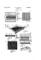
- Fig. 1 is a cross-sectional view illustrating a step in the operation of forming a primary matrix, showing a pair of press platens and interposed materials.
- Fig. 2 is a perspective view showing a textile material partially embedded in rubber-like material to form a pair of primary matrices. and partially removed therefrom.
- Fig. 3 is a plan view of a portion of-a layer of wire fabric.
- Fig. 4 is a cross-sectional view illustrating another step in the operation of forming a final molding matrix or mold, showing a pair of press platens and interposed materials.
- Fig. 5 is 4a cross-sectional view of a finished l wire fabric reinforced matrix or mold.
- Fig. 6 is a plan view of a portion of the completed belt surface.
- Fig. 7 is a cross-sectional view of the completed belt.
- Fig. 1 the first step in preparing a molding matrix corresponding to and embodying the invention is illustrated in Fig. 1.
- Pads I0, il of unvulcanized rubber or other rubber-like material, backed against spreading by layers l2, Il respectively of rubberized fabric are placed between heated press platens Il, Il.
- a layer I6 of coarsely woven textile material is placed between the two pads, the pads being dusted with powdered soapstone or other dusting material to prevent sticking of the pads t0 the fabric.
- a suitable fabric for the purpose is a stiif coarse fabric formed of heavy hemp or sisal yarns of which straight nller yarns Il and straight warps il are interwoven with crimped filler yarns I8 forming upstanding loops 2li at each face of the fabric.
- the heated platens are forced toward each other to embed the fabric in the rubber-like material and are heated to flow the material and vulcanize it.
- the platens are separated and the assembled material is removed. Then the pad material is separated from the fabric, as illustrated in Fig. 2, to provide a pair of primary matrices. either of which may be employed in the succeeding operations. Each matrix will have the impression of the textile material in its face and is useful in :making a number lof final matrices or molds.
- One of the primary matrices produced by the preceding steps, and designated 28 in Fig. 4. is then placed between heated press platens 2l, 22 together with a pad of unvulcanized rubber or other rubber-like material 23 and a layer 2l of metallic fabric.
- the pad 23 has a backing 25 of rubberized fabric or other reinforcing material afilxed thereto to prevent spreading thereof.
- the metal fabric is substantially as thick as the unvulcanized pad and is of stiff metal wire, prefy erably steel. which may be .formed with a field of upstanding loops 26 or intercoiled wire coils and straight wires 21 extending through intercalated loops of adjoining coils.
- Such a wire fabric is illustrated in Fig. 3 of the drawings. Other suitable wire fabrics may, however, be employed.
- the matrix I has the lrough fabric impression of the matrix 2l on its face and at the same time has the wire fabric embedded therein so that it is strongly reinforced by the wire fabric against spreading, while, at the same time.
- the wire loops 26 protrude vat the face of the matrix to provide additional molding surfaces.
- the indentations and projections of the rubberlike material are of less altitude than the exposed loops so as to be supported thereby against crushing and spreading.
- the unvulcanized belt material having the necessary body 4I of textile fabric or cords and an unvulcanized layer of rubber or otherrubber-like material at its face. is placed in a belt vulcanizing press, and the matrix 30 is superimposed thereon. Heat and pressure are then applied to mold and vulcanize the face of the belt to conform to the face of the matrix. As shown in Fig. 6, the resulting belt 40 has deep grooves 42 formed by the exposed coils of the wire fabric arranged in ranks of oblique grooves.
- Such a belt is well adapted for conveying packages and the like.
- the invention has the Aadvantage of making it possible to multiply greatly the number of reproductions of the original fabric, both as to molds and final products.
- a mold for forming an impression on the face of moldable material comprising a web of wire fabric material having high resistance to spreading and presenting loops of wire at a face of the web, and a layer of vulcanized rubber-like material in which said wire fabric material is partially embedded with portions of said loops exposed to present said loops together with extensive portions of the surface of the rubberlike material between the wire loops as a molding face.
- a mold for forming an impression on the face of moldable material comprising a web of wire fabric material having a high resistance to spreading and presenting loops of wire at a face of the web. and a layer of vulcanized rubber-like material in which said wire fabric material is partially embedded with portions of said loops exposed to present said loops together with extensive portions of the surface of the rubber-like material between the wire loops as a molding face, the face of said layer of rubberlike material exposed between said exposed loop portions having the form of indentations and projections.
- a mold for forming an impression on they like material exposed between said exposed loop portions having the form of indentations and projections, and said projections being of less altitude than said exposed portions of said loops.
- the method of making a mold for forming an impression on the face of moldable material which comprises forming a matrix of rubber-like material by impressing a face thereof with a coarse textile materiahpartially and permanently embedding a web of wire fabric material hav- I ing loops of wire at a face thereof in another layer of vulcanized rubber-like material by application of pressure thereto through said matrix, simultaneously forming extensive portions of the surface of the second said layer of rubber-like material by the said application of pressure by said matrix to provide between said loops exposed molding surfaces of indentations and projections' of said rubber-like material of less altitude than said exposed portions of said loops in the finished mold, and vulcanizing said rubber-like material.
- the method of permanently mounting a wire fabric facing material in a plastic backing while providing a mold face .on the backing which comprises partially embedding the wire fabric facing material in the plastic backing by pressure applied to the facing material through a layer of vulcanized yielding material having a matrix face provided with projections and indentations distortable by pressure contact with said wire fabric but more firm than said plastic backing so that said matrix face is' impressed on extensive portions of said plastic backing in the interstices of said wire fabric facing f material, and removing from said matrix face the plastic backing with its embedded wire fabric facing material to present the latter as a mold face for subsequent molding of articles against the same.
- a conveyor belt comprising a reinforced body of vulcanized rubber-like material having a resilient work-engaging face, said face com-' having diagonally striated surfaces, and still ⁇ deeper grooves also in said extensive area, said deeper grooves having smooth surfaces and each intersecting a plurality of said lateral shallow indentations.
- a conveyor belt comprising a reinforced body of vulcanized rubber-like material having a resilient work-engaging face, said face comprising an extensive area of rough projections of the rubber-like material with shallow indentations between the projections, some of said indentations extending longitudinally and some laterally of the belt, deeper short indentations Aextending longitudinally of the belt and interrupting the continuity of the laterally extending shallow indentations, all of said indentations having diagonally striated surfaces of the impression of coarse textile fabric, and still deeper grooves also in said extensive area, said deeper grooves having smooth surfaces of the impression of wire fabric and each intersecting a plurality of said shallow indentations.
- a conveyor belt comprising a reinforced body of vulcanized rubber-like material having a resilient work-engaging face, said face comprising an extensive area of rough projections of the rubber-like material with shallow indentations between the projections. some of said indentations extending longitudinally and some laterally of the belt. deeper short indentations extending longitudinally of the belt and interrupting the continuity of the laterally extending shallow indentations, all of said indentations having diagonally striated surfaces. and still deeper grooves also in said extensive area, said deeper grooves having smooth surfaces and each intersecting a plurality of said lateral shallow indentations. said deeper grooves extending diagonally of the belt and being arranged in laterally extending ranks of grooves with the grooves of successive ranks of opposite angular inclination.
- a conveyor belt comprising a reinforced body of vulcanized rubber-like material having a resilient work-engaging face. said face comprising an extensive area of rough projections of the rubber-like material with shallow indentations between the projections. some of said indentations extending longitudinally and some laterally Tof the belt. deeper short indentations sxndin, longitudmsny of the beit and mierrupting the continuity of the laterally extending shallow indentations, all of said indentations having diagonally striated surfaces, and still deeper grooves also in said extensive area. said deeper grooves having smooth surfaces and each intersecting a plurality of said lateral shallow indentations.
- said deeper grooves extending diagonallyjlof the belt and being arranged in laterallvextending ranks of grooves with the grooves f successive ranks of opposite angular inclination. and the grooves of one rank being located between the grooves of adjacent ranks in overlapping relation.
- a "conveyor belt comprising a reinforced body of rubber-like material having a resilient work-engaging face. said face comprising an extensive area of rough projections of the rubber-like material with shallow indentatioiis between the projections. some of said indental extending longitudinally and some la of thebelt.
- deeper short indentations ex 'n longitudinally ofthe belt and interrupting the continuity of the laterally extending shallow indentations, all of said indentations having diagonally striated surfaces of the impression of coarse woven textile yarns, and still deeper grooves also in said extensive area, said deeper grooves having smooth surfaces of the impression of a looped wire fabric and each intersecting a plurality of said lateral shallow indentations, said deeper grooves extending diagonally of the belt and being arranged in laterally extending ranks of grooves with the grooves of successive ranks of opposite angular inclination. and the grooves of one rank being located between the grooves of adjacent ranks in overlapping relation.
- a conveyor belt comprising a reinforced body of vulcanized rubber-like material having a resilient work-engaging face comprising alternate projections and depressions said projections providing a multiplicity of sharp edges at the face of the belt to engage articles on said face and said depressions being relatively sha1- low.
- said face also having grooves therein deeper thanY said depressions. said grooves being ar ranged in ranks lateral of the belt with the grooves in each rank inclined to the longitudinal direction of the belt and with the grooves of successively adjacent ranks inclined in opposite directions and arranged in staggered overlapping relation to each other.
- a conveyor belt comprising a reinforced body of vulcanized rubber-like material having a resilient work-engaging face comprising alternate projections and depressions said projections providing a multiplicity of sharp edges at the face of the belt to engage articles on said face and said depressions being relatively shallow.
- said face also ,having grooves therein deeper than said depressions.
- said grooves being arranged in ranks lateral of the belt with the grooves in each rank inclined to the longitudinal direction of -the belt ⁇ and with the grooves of successively adjacent ranks inclined in opposite directions. and the grooves of each rank overlapping the grooves of successively adjacent ranks and arranged in staggered overlapping relation to each other.
Landscapes
- Engineering & Computer Science (AREA)
- Mechanical Engineering (AREA)
- Belt Conveyors (AREA)
Description
Nov. 20, 1951 P. L., HUTcHlNS 2,575,813
coNvEyER BELT Filed April l, 1946 If-7 "i -Jf -j-if Passata! Nev. 2o, 1951 CONVEYEB BELT Paul L. Hutchins, Cuyahoga Falla, Ohio, aalignor to The B. F. Goodrich Company, New York, N. Y., a corporation of New York Application April 1, 194B, Serial No. 658,633
12 Claims.
l This invention relates to molding surfaces of plastic material and is especially useful in producing a rough patterned surface over the face of a conveyor belt or other flat article of rubberlike material.
In the manufacture of conveyor belts for handling packages, it is desirable to provide the loadcontacting face of the belt with rough projections and depressions for increasing the hold of the belt on the packages. Package-handling conveyor belts are of extensive areaand are vulcanized in long steam-heated presses. To provide metal molds of a size to fit such a press would be extremely expensive.
Heretofore, it has been proposed to mold such a belt by embedding a coarse woven fabric in the face of a layer of plastic rubber composition, to
vulcanize the rubber composition, and then to use the resulting matrix with 4coarse fabric face to mold the surface of the belt, as in the Reimel Patent No. 2,147,218. While such a process has been highly successful, the matrix so found is of limited useful life due to the fact that the rubber material cracks and the woven material eventually crushes in use.
Objects of the present invention are to provide for resisting cracking of the matrix to provide a molding surface of the desired complex roughness, to provide projection and indentations of greater depthl and variety of form, to provide an improved matrix of increased useful life, and to provide an improved belt product.
further object is to provide for making a multiplicity of molds and resulting products from each original fabric used for reproduction.
These and other objects will appear from the following description and the accompanying drawings.
Of the drawings.
Fig. 1 is a cross-sectional view illustrating a step in the operation of forming a primary matrix, showing a pair of press platens and interposed materials.
Fig. 2 is a perspective view showing a textile material partially embedded in rubber-like material to form a pair of primary matrices. and partially removed therefrom.
Fig. 3 is a plan view of a portion of-a layer of wire fabric.
Fig. 4 is a cross-sectional view illustrating another step in the operation of forming a final molding matrix or mold, showing a pair of press platens and interposed materials.
Fig. 5 is 4a cross-sectional view of a finished l wire fabric reinforced matrix or mold.
- 2 Fig. 6 is a plan view of a portion of the completed belt surface.
Fig. 7 is a cross-sectional view of the completed belt.
Referring to the drawings, the first step in preparing a molding matrix corresponding to and embodying the invention is illustrated in Fig. 1. Pads I0, il of unvulcanized rubber or other rubber-like material, backed against spreading by layers l2, Il respectively of rubberized fabric are placed between heated press platens Il, Il. A layer I6 of coarsely woven textile material is placed between the two pads, the pads being dusted with powdered soapstone or other dusting material to prevent sticking of the pads t0 the fabric. A suitable fabric for the purpose is a stiif coarse fabric formed of heavy hemp or sisal yarns of which straight nller yarns Il and straight warps il are interwoven with crimped filler yarns I8 forming upstanding loops 2li at each face of the fabric. The heated platens are forced toward each other to embed the fabric in the rubber-like material and are heated to flow the material and vulcanize it.
After vulcanization is complete, the platens are separated and the assembled material is removed. Then the pad material is separated from the fabric, as illustrated in Fig. 2, to provide a pair of primary matrices. either of which may be employed in the succeeding operations. Each matrix will have the impression of the textile material in its face and is useful in :making a number lof final matrices or molds.
One of the primary matrices produced by the preceding steps, and designated 28 in Fig. 4. is then placed between heated press platens 2l, 22 together with a pad of unvulcanized rubber or other rubber-like material 23 and a layer 2l of metallic fabric. The pad 23 has a backing 25 of rubberized fabric or other reinforcing material afilxed thereto to prevent spreading thereof. The metal fabric is substantially as thick as the unvulcanized pad and is of stiff metal wire, prefy erably steel. which may be .formed with a field of upstanding loops 26 or intercoiled wire coils and straight wires 21 extending through intercalated loops of adjoining coils. Such a wire fabric is illustrated in Fig. 3 of the drawings. Other suitable wire fabrics may, however, be employed.
With the wire fabric 2| located between the primary matrix 2l and the pad 23, pressure is applied to the assembly by the heated platens to y embed the wire fabric in the pad 23 and at the same time to impress the face vof the pad 2l with 'illustrated in section in Fig. 5, is removed therefrom. The matrix I has the lrough fabric impression of the matrix 2l on its face and at the same time has the wire fabric embedded therein so that it is strongly reinforced by the wire fabric against spreading, while, at the same time. the wire loops 26 protrude vat the face of the matrix to provide additional molding surfaces. The indentations and projections of the rubberlike material are of less altitude than the exposed loops so as to be supported thereby against crushing and spreading.
In the manufacture of a conveyor belt such as illustrated in Figs. 6 and 7, the unvulcanized belt material having the necessary body 4I of textile fabric or cords and an unvulcanized layer of rubber or otherrubber-like material at its face. is placed in a belt vulcanizing press, and the matrix 30 is superimposed thereon. Heat and pressure are then applied to mold and vulcanize the face of the belt to conform to the face of the matrix. As shown in Fig. 6, the resulting belt 40 has deep grooves 42 formed by the exposed coils of the wire fabric arranged in ranks of oblique grooves. with the grooves of successive rows inclined obliquely in opposite directions, and between the grooves 42 the surface is formed with projections 43 and indentations 44 of less depth than the'grooves 42 and having a form resulting from molding contact with the matrix 28. Such a belt is well adapted for conveying packages and the like.
In addition to the improved rough character of the final products, the invention has the Aadvantage of making it possible to multiply greatly the number of reproductions of the original fabric, both as to molds and final products.
Variations may be made without departing from the scope of the invention as it is defined by the following claims.
I claim:
1. A mold for forming an impression on the face of moldable material, said mold comprising a web of wire fabric material having high resistance to spreading and presenting loops of wire at a face of the web, and a layer of vulcanized rubber-like material in which said wire fabric material is partially embedded with portions of said loops exposed to present said loops together with extensive portions of the surface of the rubberlike material between the wire loops as a molding face.
2. A mold for forming an impression on the face of moldable material, said mold comprising a web of wire fabric material having a high resistance to spreading and presenting loops of wire at a face of the web. and a layer of vulcanized rubber-like material in which said wire fabric material is partially embedded with portions of said loops exposed to present said loops together with extensive portions of the surface of the rubber-like material between the wire loops as a molding face, the face of said layer of rubberlike material exposed between said exposed loop portions having the form of indentations and projections.
3. A mold for forming an impression on they like material exposed between said exposed loop portions having the form of indentations and projections, and said projections being of less altitude than said exposed portions of said loops.
4. The method of making a mold for forming an impression on the face of moldable material which comprises forming a matrix of rubber-like material by impressing a face thereof with a coarse textile materiahpartially and permanently embedding a web of wire fabric material hav- I ing loops of wire at a face thereof in another layer of vulcanized rubber-like material by application of pressure thereto through said matrix, simultaneously forming extensive portions of the surface of the second said layer of rubber-like material by the said application of pressure by said matrix to provide between said loops exposed molding surfaces of indentations and projections' of said rubber-like material of less altitude than said exposed portions of said loops in the finished mold, and vulcanizing said rubber-like material.
5. The method of permanently mounting a wire fabric facing material in a plastic backing while providing a mold face .on the backing, which comprises partially embedding the wire fabric facing material in the plastic backing by pressure applied to the facing material through a layer of vulcanized yielding material having a matrix face provided with projections and indentations distortable by pressure contact with said wire fabric but more firm than said plastic backing so that said matrix face is' impressed on extensive portions of said plastic backing in the interstices of said wire fabric facing f material, and removing from said matrix face the plastic backing with its embedded wire fabric facing material to present the latter as a mold face for subsequent molding of articles against the same.
6. A conveyor belt comprising a reinforced body of vulcanized rubber-like material having a resilient work-engaging face, said face com-' having diagonally striated surfaces, and still` deeper grooves also in said extensive area, said deeper grooves having smooth surfaces and each intersecting a plurality of said lateral shallow indentations.
'7. A conveyor belt comprising a reinforced body of vulcanized rubber-like material having a resilient work-engaging face, said face comprising an extensive area of rough projections of the rubber-like material with shallow indentations between the projections, some of said indentations extending longitudinally and some laterally of the belt, deeper short indentations Aextending longitudinally of the belt and interrupting the continuity of the laterally extending shallow indentations, all of said indentations having diagonally striated surfaces of the impression of coarse textile fabric, and still deeper grooves also in said extensive area, said deeper grooves having smooth surfaces of the impression of wire fabric and each intersecting a plurality of said shallow indentations.
8. A conveyor belt comprising a reinforced body of vulcanized rubber-like material having a resilient work-engaging face, said face comprising an extensive area of rough projections of the rubber-like material with shallow indentations between the projections. some of said indentations extending longitudinally and some laterally of the belt. deeper short indentations extending longitudinally of the belt and interrupting the continuity of the laterally extending shallow indentations, all of said indentations having diagonally striated surfaces. and still deeper grooves also in said extensive area, said deeper grooves having smooth surfaces and each intersecting a plurality of said lateral shallow indentations. said deeper grooves extending diagonally of the belt and being arranged in laterally extending ranks of grooves with the grooves of successive ranks of opposite angular inclination.
9. A conveyor belt comprising a reinforced body of vulcanized rubber-like material having a resilient work-engaging face. said face comprising an extensive area of rough projections of the rubber-like material with shallow indentations between the projections. some of said indentations extending longitudinally and some laterally Tof the belt. deeper short indentations sxndin, longitudmsny of the beit and mierrupting the continuity of the laterally extending shallow indentations, all of said indentations having diagonally striated surfaces, and still deeper grooves also in said extensive area. said deeper grooves having smooth surfaces and each intersecting a plurality of said lateral shallow indentations. said deeper grooves extending diagonallyjlof the belt and being arranged in laterallvextending ranks of grooves with the grooves f successive ranks of opposite angular inclination. and the grooves of one rank being located between the grooves of adjacent ranks in overlapping relation.
10. A "conveyor belt comprising a reinforced body of rubber-like material having a resilient work-engaging face. said face comprising an extensive area of rough projections of the rubber-like material with shallow indentatioiis between the projections. some of said indental extending longitudinally and some la of thebelt. deeper short indentations ex 'n longitudinally ofthe belt and interrupting the continuity of the laterally extending shallow indentations, all of said indentations having diagonally striated surfaces of the impression of coarse woven textile yarns, and still deeper grooves also in said extensive area, said deeper grooves having smooth surfaces of the impression of a looped wire fabric and each intersecting a plurality of said lateral shallow indentations, said deeper grooves extending diagonally of the belt and being arranged in laterally extending ranks of grooves with the grooves of successive ranks of opposite angular inclination. and the grooves of one rank being located between the grooves of adjacent ranks in overlapping relation.
11. A conveyor belt comprising a reinforced body of vulcanized rubber-like material having a resilient work-engaging face comprising alternate projections and depressions said projections providing a multiplicity of sharp edges at the face of the belt to engage articles on said face and said depressions being relatively sha1- low. said face also having grooves therein deeper thanY said depressions. said grooves being ar ranged in ranks lateral of the belt with the grooves in each rank inclined to the longitudinal direction of the belt and with the grooves of successively adjacent ranks inclined in opposite directions and arranged in staggered overlapping relation to each other.
l2. A conveyor belt comprising a reinforced body of vulcanized rubber-like material having a resilient work-engaging face comprising alternate projections and depressions said projections providing a multiplicity of sharp edges at the face of the belt to engage articles on said face and said depressions being relatively shallow. said face also ,having grooves therein deeper than said depressions. said grooves being arranged in ranks lateral of the belt with the grooves in each rank inclined to the longitudinal direction of -the belt `and with the grooves of successively adjacent ranks inclined in opposite directions. and the grooves of each rank overlapping the grooves of successively adjacent ranks and arranged in staggered overlapping relation to each other.
PAUL L. HUTCHINB.
REFERENCES CITED The following references are of record in the me of this patent:
UNITED STATES PATENTS 2,380,230 Gatke July 10. 1945
Priority Applications (1)
| Application Number | Priority Date | Filing Date | Title |
|---|---|---|---|
| US658633A US2575813A (en) | 1946-04-01 | 1946-04-01 | Conveyer belt |
Applications Claiming Priority (1)
| Application Number | Priority Date | Filing Date | Title |
|---|---|---|---|
| US658633A US2575813A (en) | 1946-04-01 | 1946-04-01 | Conveyer belt |
Publications (1)
| Publication Number | Publication Date |
|---|---|
| US2575813A true US2575813A (en) | 1951-11-20 |
Family
ID=24642037
Family Applications (1)
| Application Number | Title | Priority Date | Filing Date |
|---|---|---|---|
| US658633A Expired - Lifetime US2575813A (en) | 1946-04-01 | 1946-04-01 | Conveyer belt |
Country Status (1)
| Country | Link |
|---|---|
| US (1) | US2575813A (en) |
Cited By (14)
| Publication number | Priority date | Publication date | Assignee | Title |
|---|---|---|---|---|
| US3019062A (en) * | 1958-09-24 | 1962-01-30 | Aircraft Armaments Inc | Tractor track |
| US3027200A (en) * | 1959-11-16 | 1962-03-27 | Aircraft Armaments Inc | Tractor tracks |
| US3169632A (en) * | 1962-02-28 | 1965-02-16 | Arthur F Kain | Magnetic belt and trainer |
| US3179241A (en) * | 1962-02-28 | 1965-04-20 | Arthur F Kain | Magnetic belt trainer |
| US3608702A (en) * | 1969-09-29 | 1971-09-28 | Joseph Fraioli Sr | Conveyor belt |
| US3961875A (en) * | 1973-07-18 | 1976-06-08 | Colonial Rubber Works, Inc. | Apparatus for making carpet underlay |
| US4162727A (en) * | 1977-10-26 | 1979-07-31 | Fabreeka Products Company | Conveyor belt |
| US4364554A (en) * | 1981-01-26 | 1982-12-21 | Bell & Howell Company | Conveyor arrangement for mail sorting machines |
| US4432540A (en) * | 1981-02-05 | 1984-02-21 | Bell & Howell Company | Mail sorting machine with improved conveyor and envelope separating device |
| US4705469A (en) * | 1985-11-06 | 1987-11-10 | Egokiefer Ag | Apparatus for making a flexible link belt |
| US5495935A (en) * | 1994-08-12 | 1996-03-05 | Globe International Inc. | Conveyor belting and method of manufacture |
| WO1997018148A1 (en) * | 1995-11-16 | 1997-05-22 | Habasit Globe, Inc. | Improved conveyor belting and method of manufacture |
| WO2015106735A1 (en) * | 2014-01-16 | 2015-07-23 | Forbo Siegling Gmbh | Conveyor belt and conveying device equipped with said conveyor belt |
| CN106573730A (en) * | 2014-06-03 | 2017-04-19 | 福尔波西格林日本有限公司 | Conveyor belt |
Citations (3)
| Publication number | Priority date | Publication date | Assignee | Title |
|---|---|---|---|---|
| US137224A (en) * | 1873-03-25 | Improvement in feed and delivery aprons | ||
| US2147218A (en) * | 1936-11-11 | 1939-02-14 | Goodrich Co B F | Mold for and method of molding rubber articles |
| US2380230A (en) * | 1939-11-29 | 1945-07-10 | Thomas L Gatke | Apparatus for producing composition brake lining material in transversely grooved strip form |
-
1946
- 1946-04-01 US US658633A patent/US2575813A/en not_active Expired - Lifetime
Patent Citations (3)
| Publication number | Priority date | Publication date | Assignee | Title |
|---|---|---|---|---|
| US137224A (en) * | 1873-03-25 | Improvement in feed and delivery aprons | ||
| US2147218A (en) * | 1936-11-11 | 1939-02-14 | Goodrich Co B F | Mold for and method of molding rubber articles |
| US2380230A (en) * | 1939-11-29 | 1945-07-10 | Thomas L Gatke | Apparatus for producing composition brake lining material in transversely grooved strip form |
Cited By (18)
| Publication number | Priority date | Publication date | Assignee | Title |
|---|---|---|---|---|
| US3019062A (en) * | 1958-09-24 | 1962-01-30 | Aircraft Armaments Inc | Tractor track |
| US3027200A (en) * | 1959-11-16 | 1962-03-27 | Aircraft Armaments Inc | Tractor tracks |
| US3169632A (en) * | 1962-02-28 | 1965-02-16 | Arthur F Kain | Magnetic belt and trainer |
| US3179241A (en) * | 1962-02-28 | 1965-04-20 | Arthur F Kain | Magnetic belt trainer |
| US3608702A (en) * | 1969-09-29 | 1971-09-28 | Joseph Fraioli Sr | Conveyor belt |
| US3961875A (en) * | 1973-07-18 | 1976-06-08 | Colonial Rubber Works, Inc. | Apparatus for making carpet underlay |
| US4162727A (en) * | 1977-10-26 | 1979-07-31 | Fabreeka Products Company | Conveyor belt |
| US4364554A (en) * | 1981-01-26 | 1982-12-21 | Bell & Howell Company | Conveyor arrangement for mail sorting machines |
| US4432540A (en) * | 1981-02-05 | 1984-02-21 | Bell & Howell Company | Mail sorting machine with improved conveyor and envelope separating device |
| US4705469A (en) * | 1985-11-06 | 1987-11-10 | Egokiefer Ag | Apparatus for making a flexible link belt |
| US5495935A (en) * | 1994-08-12 | 1996-03-05 | Globe International Inc. | Conveyor belting and method of manufacture |
| US5906269A (en) * | 1994-08-12 | 1999-05-25 | Habasit Globe, Inc. | Conveyor belting and method of manufacture |
| WO1997018148A1 (en) * | 1995-11-16 | 1997-05-22 | Habasit Globe, Inc. | Improved conveyor belting and method of manufacture |
| WO2015106735A1 (en) * | 2014-01-16 | 2015-07-23 | Forbo Siegling Gmbh | Conveyor belt and conveying device equipped with said conveyor belt |
| KR20160104704A (en) * | 2014-01-16 | 2016-09-05 | 포르보 지글링 게엠베하 | Conveyor belt and conveying device equipped with said conveyor belt |
| US9708127B2 (en) | 2014-01-16 | 2017-07-18 | Forbo Siegling Gmbh | Conveyor belt and conveying device equipped with said conveyor belt |
| CN106573730A (en) * | 2014-06-03 | 2017-04-19 | 福尔波西格林日本有限公司 | Conveyor belt |
| US9950865B2 (en) * | 2014-06-03 | 2018-04-24 | Forbo Siegling Japan Ltd. | Conveyor belt |
Similar Documents
| Publication | Publication Date | Title |
|---|---|---|
| US2575813A (en) | Conveyer belt | |
| US4174991A (en) | Process of laminating carpet to elastomeric backing | |
| US3235438A (en) | Molded elastomeric product having integral flexible hair-like filaments | |
| US3945417A (en) | Lugged vehicle tire, and method of building same | |
| CN1374904A (en) | Cleat-forming woven fabric article for the manufacture of anti-creep floor mats | |
| US2288054A (en) | Method of making rubber flooring | |
| US2147218A (en) | Mold for and method of molding rubber articles | |
| US1426672A (en) | Retread for tires and method of making them | |
| CA1335649C (en) | Dust control mat with non-cleated borders | |
| US4731139A (en) | Method for preparing an embossed laminate containing at least two layers | |
| US4902465A (en) | Process for forming dust control mat with non-cleated borders | |
| US3290195A (en) | Method of making a v-belt | |
| US1205345A (en) | Reinforced vulcanizable article and method of producing the same. | |
| US2037105A (en) | Laminated article and method of manufacture | |
| US567985A (en) | Stair-pad or the like | |
| US2356225A (en) | Decorated fabric | |
| US1687441A (en) | Tread material and method of making the same | |
| US3256376A (en) | Method for continuously producing flat mats | |
| US3993521A (en) | Lugged vehicle tire, and method of building same | |
| US1118315A (en) | Manufacture of cup-packing of composite material. | |
| US3439083A (en) | Process for manufacture of a mat or carpet like the two-colour rubber mats molded | |
| US2619753A (en) | Method of making decorative sheets | |
| US3193425A (en) | Edge bonding of conveyor belts | |
| US3300557A (en) | Manufacturing rubber sheets provided with a relief pattern | |
| US1673505A (en) | Heel mold |