US2575366A - Oxygen regulator - Google Patents
Oxygen regulator Download PDFInfo
- Publication number
- US2575366A US2575366A US675284A US67528446A US2575366A US 2575366 A US2575366 A US 2575366A US 675284 A US675284 A US 675284A US 67528446 A US67528446 A US 67528446A US 2575366 A US2575366 A US 2575366A
- Authority
- US
- United States
- Prior art keywords
- valve
- pressure
- diaphragm
- oxygen
- chamber
- Prior art date
- Legal status (The legal status is an assumption and is not a legal conclusion. Google has not performed a legal analysis and makes no representation as to the accuracy of the status listed.)
- Expired - Lifetime
Links
- QVGXLLKOCUKJST-UHFFFAOYSA-N atomic oxygen Chemical compound [O] QVGXLLKOCUKJST-UHFFFAOYSA-N 0.000 title description 76
- 229910052760 oxygen Inorganic materials 0.000 title description 76
- 239000001301 oxygen Substances 0.000 title description 76
- 230000029058 respiratory gaseous exchange Effects 0.000 description 36
- 230000001276 controlling effect Effects 0.000 description 18
- 230000007246 mechanism Effects 0.000 description 9
- MYMOFIZGZYHOMD-UHFFFAOYSA-N Dioxygen Chemical compound O=O MYMOFIZGZYHOMD-UHFFFAOYSA-N 0.000 description 5
- 244000273618 Sphenoclea zeylanica Species 0.000 description 5
- 230000009471 action Effects 0.000 description 5
- 238000010276 construction Methods 0.000 description 5
- 239000000203 mixture Substances 0.000 description 5
- 208000020401 Depressive disease Diseases 0.000 description 2
- 210000002345 respiratory system Anatomy 0.000 description 2
- FYYHWMGAXLPEAU-UHFFFAOYSA-N Magnesium Chemical compound [Mg] FYYHWMGAXLPEAU-UHFFFAOYSA-N 0.000 description 1
- 102100028644 Tenascin-R Human genes 0.000 description 1
- 230000006978 adaptation Effects 0.000 description 1
- XAGFODPZIPBFFR-UHFFFAOYSA-N aluminium Chemical compound [Al] XAGFODPZIPBFFR-UHFFFAOYSA-N 0.000 description 1
- 229910052782 aluminium Inorganic materials 0.000 description 1
- 230000008878 coupling Effects 0.000 description 1
- 238000010168 coupling process Methods 0.000 description 1
- 238000005859 coupling reaction Methods 0.000 description 1
- IWEDIXLBFLAXBO-UHFFFAOYSA-N dicamba Chemical compound COC1=C(Cl)C=CC(Cl)=C1C(O)=O IWEDIXLBFLAXBO-UHFFFAOYSA-N 0.000 description 1
- 238000007865 diluting Methods 0.000 description 1
- 230000000694 effects Effects 0.000 description 1
- 239000003562 lightweight material Substances 0.000 description 1
- 229910052749 magnesium Inorganic materials 0.000 description 1
- 239000011777 magnesium Substances 0.000 description 1
- 230000002093 peripheral effect Effects 0.000 description 1
- 230000001105 regulatory effect Effects 0.000 description 1
- 230000004044 response Effects 0.000 description 1
- 230000002441 reversible effect Effects 0.000 description 1
- 108010020387 tenascin R Proteins 0.000 description 1
- 238000013022 venting Methods 0.000 description 1
Images


Classifications
-
- A—HUMAN NECESSITIES
- A62—LIFE-SAVING; FIRE-FIGHTING
- A62B—DEVICES, APPARATUS OR METHODS FOR LIFE-SAVING
- A62B9/00—Component parts for respiratory or breathing apparatus
- A62B9/02—Valves
-
- Y—GENERAL TAGGING OF NEW TECHNOLOGICAL DEVELOPMENTS; GENERAL TAGGING OF CROSS-SECTIONAL TECHNOLOGIES SPANNING OVER SEVERAL SECTIONS OF THE IPC; TECHNICAL SUBJECTS COVERED BY FORMER USPC CROSS-REFERENCE ART COLLECTIONS [XRACs] AND DIGESTS
- Y10—TECHNICAL SUBJECTS COVERED BY FORMER USPC
- Y10T—TECHNICAL SUBJECTS COVERED BY FORMER US CLASSIFICATION
- Y10T137/00—Fluid handling
- Y10T137/1842—Ambient condition change responsive
- Y10T137/1939—Atmospheric
- Y10T137/2012—Pressure
Landscapes
- Health & Medical Sciences (AREA)
- Pulmonology (AREA)
- General Health & Medical Sciences (AREA)
- Business, Economics & Management (AREA)
- Emergency Management (AREA)
- Respiratory Apparatuses And Protective Means (AREA)
Description
Nov. 20, 1951 c. H. SOLLMANN I 2,575,366
OXYGEN REGULATOR Filed June 7, 1946 I s Sheets-Sheet 1 IN VEN TOR.
kwwaw ATTORNEY Nov. 20, 1 c. H. SOLL-MANN 2,575,365
I OXYGEN REGULATOR Filed June '7, 1946 3 Sheets-Sheet 2 IN V EN TOR.
ATTORNEY Nov. 20, 195] c. H. SOLLMANN 2,575,366
OXYGEN REGULATOR Filed June '7, 1946 3 Sheets-Sheet I5 IN V EN TOR.
BY 4M. 52%??? M d, a 1
ATTORNEY "respiratory system.
Patented Nov. 20, 1951 UNITED STATES PATENT OFFICE.
1: Claims. (Cl. 128-142) 'i I This invention relates to improvements in oxygen'regulators and particularly to devices for regulating the flow of oxygenand/or the oxygen and air ratio in breathing devices.
The device of-the present invention is particularlywell adapted for use in-aircraft at high altitude's for supplying the proper amount of oxygen and/or oxygen and air -mixtures for breathing purposes.
Devices of this character as heretofore known have been of such size and weight as to be-unsuited for insertion-or adaptation to breathing masks. v
Accordingly, one-bf the objects'of' the present inventionis the provision of a device ofthe character indicated which has many advantages over.
and overcomes inherent disadvantages in, such device'as heretofore known.
Another. object of the invention'resides in the provision of-a device which is compact, light in weight, and of rigid construction, .desiderata in devices of this character.
-A further obiectof the invention is. thefpro vision-of a device of thecharacter indicated which can be mounted'on and carried by a mask.
A further object of the invention resides in the provision cf -a. device of the character indicated which isentir'ely automatic and which regulates the oxygen and/or the oxygen-air; ratio to provide for proper breathing at various aItitudes. A further object of theinvention resides in the provision of a device which, at all times,. is
under the automatic control of the operator's A "still further object of the invention resides in the provision of a. device of the character-indicated wherein the automatic regulationffaisjaccomplished through the medium of a noye'i'talve mechanism and valve control means actuated by the human respiratory system. V
Other and further objects-of the invention-will be obvious uponan understanding of the illustrative embodiment about to be described,;;or'jwill be indicated in the appended claims, and various advantages not referred to herein will occur to oneskllled in the art upon employment of the invention. in practice. Y H
A preferred embodiment of the invention has been chosen for purposes of illustration and description and is shown in the accompanying drawings, forming-apart of the specification, wherein:
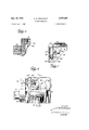
2 Figure l is a sectional elevational view of a device in accordance, with the invention. I
Figure 2 is a sectional view taken on line 2-2 of' Figure 1.
Figure 3 is a top view thereof. 7 Figure 4 is a side elevational view of the device.
Figure 5 is a fragmentary sectional view onv line 5-5 of Figure 1.
Figure 6 is a side elevational view partly in section.
Figure 7 is a fragmentary sectional view taken on line 1-1 of Figure 6; and
Figure 8 is a sectional view of a modified form .of the device showing the same applied to a mask. & I
Referring to the drawings in detail, the unit shown may be adapted for use with breathing equipment of any kind, such as that wherein the unit may be supported separately from the user, or on his chest, or otherwise, the embodiment chosen for illustration is one in which the construction which willbe apparent from the following explanation of the principles, construction and operation involved.
Referring to the drawings in detail and more particularly to Figures 1 to 7 thereof, thereis shown an oxygen regulator in accordance'with the invention having a terminal or coupling element l8 constituting an oxygen inlet to which oxygen is adapted to be;supplied from a suitable source by means of a valve controlled conduit (not shown).
From the inlet IS, the oxygen is conducted through a conduit l8 to a main or demand valve chamber housing 20, a main or demand valve 2| and an outlet 22. The main valve 21 includes a valve member 24 for engagement with a main jbellows 4|. This casing is formed with a Jet 16 and the fixed housing 40 carries'a needle valve mixing chamber 34.
member I09 so that, when the diluter casing is moved by the bellows, the jet 36 moves relative to the valve member I09 whereby the latter will con trol the flow 01' oxygen through the jet 38 to a The housing 40 and the Jet 36 are disposed in alignment with a respirator 42 having a check valve 44 therein. The diluter 33 and mixing chamber 34 are employed when the device is utilized to supply a mixture of air and oxygen as will be described in more detail hereinafter.
The main valve member 24 is provided with a hollow valve stem or sleeve 46 which constitutes a single conduit providing communication between the main valve chamber housing 20 and the pressure side 48 of a main valve operating diaphragm 50 to which the stem 46 is connected,
58 which is connected to a pilot diaphragm 60 in a pilot diaphragm chamber 62. An adjustable spring mechanism 84 urges the pilot diaphragm 80 toward the open position of the pilot valve member 58 relative to the seat 51. An exhaust conduit 86 of the respirator 42 communicates with pressure side I0 of the pilot diaphragm 60 in the chamber 62, whereby exhalation pressure is built up on the pressure side 10 of the pilot diaphragm to close the pilot valve 58, and on inhalation the said pressure is released whereby to permit the pilot valve to open-under the action of the spring mechanism 84.
The respirator 42 is provided with a mouth piece I2 (Figure l), which may be received by the lips of the user when no mask is employed, and which fits into an intake or mouth piece receptacle 14 of a mask I8 when the device is employed with a, mask as shown in fragmentary view in Figure .1. The respirator has an inlet facing the jet 36 and has an outlet extending oxygen supply source I0to release oxygen directly to the inlet IS. The check valve 44 and the pilot valve diaphragm- 80 are so delicately respcnsive to breath pressure that the first efiect after opening the discharge valve I2 will depend upon whether the user, or aviator, is inhaling or exhaling at the moment.
If he is exhaling, the check valve 44 will close. whereby, the exhalation pressure will be by passed through conduit to the pilot diaphragm 60 and will close the pilot valve 58, whereupon the oxygen pressure through the main valve member 24 and its stem 46, and through the conduit 56 to the pilot'valve 54, will build up and operate as a back pressure against the main valve diaphragm 50 which will move the main valve member 24 against the action of the spring 28 to seat against the seat 26 andclose communication between the conduit I8 and outlet 22, thereby stopping the flow of oxygen to the respirator42. 1; a
Upon inhala on, the reverse action takes place, resulting in the release of exhalation pressure, on the check .valve 44 permitting the same to open, and the release of pressure on the pilot diaphragm permitting the spring mechanism 5 64 to open the pilot valve 54. This action relieves the pressure on the mairryalve diaphragm 50, whereupon the main valve member 24 moves from its seat 26 under the action of spring 28 and establishes communication through the main valve chamber 20 from the conduit! to the outlet 22, and from the latter through the conduit 30, the chamber 32 and the chamber 34 to the respirator 42.
In breathing equipment as heretofore employed, it was necessary for the user to breathe directly against a diaphragm and the main flow oxygen pressure, there being no mechanism provided corresponding to the pilot valve 54. Therefore, to operate such prior devices, it was necessary to provide a diaphragm of very great area.
In applicant's device, the actual force at the pilot valve is so small that the area of the diaphragm is but a very small fraction of the area of the diaphragm formerly employed. Moreover, since the oxygen pressure itself is many times that of exhalation, the'main valve diaphragm of the device'fof the present invention is also very greatly reduced in area.
'The-unit of the present invention, although it employs two diaphragms, is so compact and the bulk and weight of the regulator as a whole is so reduced over prior devices that it is readily'adaptable as a component part of 'a mask unit, which has not heretofore been possible.
The breathing equipment of the present invention is suitable for use at high altitudes, or under other circumstances where a supply of pure oxygen may be desired instead of a mixture of air and oxy en.
In such case, the device of the present invention is provided with means whereby the air supply can be shut off, or as shown in Figure 8, the aneroid bellows, and diluter features are eliminated as wil1 be described hereinafter.
' When the device thus far described is to be employed for supplying pure oxygen, such as is required at very-high altitudes,'the diluter is rendered ineffective-'30 that there is no mixing of the oxygen with air. 'This is accomplished by manually moving the jet 36 to the left, as viewed in Figure l, by means of a knob secured by a screw-82 to a slide 84. The slide 84 has an inwardlyextending projection 86 inalignment with an annular shoulder 88 on the :let 38, whereby upon engagement of the projection 86 therewith the jet is moved to close off air inlet 90. With the air supply closed off as just described pure oxygen is fed directly to the respirator 42. 'The jet is adapted to be latched in. closed position by means of a leaf spring 92 secured at one end to a main housing 94 having a detent 95 at its free end. This detent is adapted to be latched in notches 98 and I00 formed in the'inner face of the slide 84. In the position illustrated the slide is latched in position to permit the jet to open. Should the slide be moved to the left to close the jet, the detent 96 of the spring 92 will engage the notch 88 whereby to latch the jet in closed position.
The housing 94, preferably is of light weight material such as aluminum, magnesium, plastic or the like, and is provided with a removable cover I02 which supports a screen 104' whereby air is admitted to the housing. This housing 20 is .provided with the oxygen inlet couplin I8 and which as. previously mentioned communicates with the oxygen supply source.
7 When it is desired that the supply to the operator be a mixture -of oxygen and air,. the diluter 33 shown in Figure l is brought intooperation. -This diluter comprises the aneroid bellows 4I secured to the housing 94 by a nut I06 which is screwed on a threaded projection I01 of the bellows. The bellows is adapted to expand and contract in accordance with different atmospheric pressures at different altitudes. The bellows 4| is provided with a recess I08 for the reception of the diluter casing (Figure 1), and this casing is actuated by the bellows 4I automatically in accordance 'with altitude. The needle valve I has a valve stem IIO provided with a threade end for securing the same in the housing 40. casing or housing 94 by means of screws II2 (Figure 2). The diluter casing, in which the jet 36 is formed, is normally urged by a spring II4 to the right. as viewed in Figure 1. The needle valve I09 is tapered, whereby to provide a metering valve for oxygen passing from the chamber 32 to the mixing chamber 34 through the jet 36.
When the bellows 4I expands, the end of the diluter casing in which the jet 36 is formed will be moved toward the mixing chamber 34, relatively to the housing 40, whereby to reduce the amount of air passing through the air inlet 90, and when the bellows expands sufliciently the wall of the diluter casing surrounding the jet 36 will engage a seat H8 and close 011? the air supply completely so that only oxygen will pass to the respirator 42, in the same manner as when the air inlet is closed manually as previously described.
On inhaling through the respirator 42, the check valve 44 is opened to the mixing chamber 34. When the air inlet 90 is open, air is free topass into the mixing chamber from the interior of the housing 94, and oxygen will be fed to the mixing chamber from the source of supply, in the manner hereinbefore described. whereby the air and oxygen will be mixed in the chamber 34. When the air inlet 90 is closed pure oxygen from the chamber 34 will pass the valve I09, as previously mentioned.
The tension on the diaphragm 60 is adjustable by means of the spring mechanism 64 whereby the pressure required to close valve 58 is determined. This mechanism includes a leaf spring 65 which is under an upward force exerted by torsion spring 68 (Figure 6) which torsion spring is fastened to and adapted to be manually adjusted by the rotation of rod 13.
One end of the rod 13 is pinned to locking sector 68 (Figure 7) having notches 83 in its periphery. The other end of the rod 13 is pinned to knob 19. Detent spring BI is arranged to hold sector 18 in either of two predetermined positions. It is to be understood that additional notches may be provided in the sector whereby the same may be held in additional positions.
'Rotation of rod 13 winds or unwinds the torsion spring depending on the direction the knob 19 is turned.
When the diaphragm 80 is operated to open the main valve 2|, the oxygen passing through the valve stem 46 of the valve 24 and through the conduit 56 escapes to the interior of the housing and commingles with the air therein so that 'regardless of the amount of oxygen supplied by the diluting mechanism there will also be a certain quantity of oxygen in the air drawn into the mouthpiece.
The unit shown in Figure 8 is designed for .1188 at high altitudes where pure oxygen is desired and accordingly this unit is not provided The housing 40 is secured to the with a diluter or aneroid bellows. In many other respects, however, the unit of this figure issubstantially the same as that of Figures 1 to 7 inclusive, in that it is provided with the novel main demand and a pilot valve. The m'ain valve in this figure is designated I50 and :has a valve member I52 adapted to be seated against a valve seat I54. This valve is similar in construction to the valve 2I of Figure 1 in that it has a hollow stem I56 secured to adiaphragm I58 and provided with a spring I60 i'or urging the valve toward its seat I54. The hollow stem communicates with the pressure side of the'diaphragm I56.
This unit also has a pilot diaphragm I62 which carries a valve member I64. This valve member serves the same function as the valve member I09 of Figure 1, but instead of it being'of the needle valve type it engages a ball valve I66. which is adapted to seat on valve seat I68 to close off the escape of pressure from the pressure side of the diaphragm I58 whereby pressure is built up therein to seat the valve I52 and close oil the supply of oxygen upon exhalation, as in the previously described embodiment of the invention. A conduit or communicatin passageway I10 comparable to the conduit 66 of Figure 1 is provided in the housing I'II leading from a respirator I12 to the pressure side I14 of the pilot diaphragm I62, whereby to actuate the diaphragm as aforesaid.
The pilot valve stem I64 is adapted to be locked in valve closed position by means of a locking pin I16 adapted to be engaged by an arm I18 pivoted to the housing I1I at I80. This arm is adapted to be actuated by a valve looking cam I82 which is keyed to a shaft I84.
A look wheel I88 is also mounted on the shaft I84, and is provided with peripheral depressions I 88, which in this case are six in number, and are adapted to be engaged by a ball I90 which is held in engagement with one of the depressions I88 by means of a spring (not shown).
A check valve is provided for the respirator I12 for venting exhalation pressure in excess of that passing through conduit I10 to the pressure side of the pilot diaphragm. The excess exhalation pressure is vented to atmosphere by way of passageway I15. The check valve comprises a valve disk I92 and a valve stem I94 adapted to slide in a sleeve I96 mounted in the respirator. A lever I98 pivotally mounted at 200 to the housing I1I has a projecting arm 202 carrying a pin 204 which is engaged by a spring 2I8 whereby to maintain the lever in engagement with the check valve disc I92. Two torsion springs 2I8 and 220 are keyed to a shaft I84 which shaft is adapted to be manually'operated and set in various positions upon rotation of an adjusting knob (not shown), secured to the shaft at the outside of the housing. Upon rotation of this knob in a direction to wind up the torsion springs 2I8 and 220, the spring 2I8 will increase the force on the check valve I92 through the medium of arm 202' and lever I98. and spring 220 will increase the force on the diaphragm I62 through the medium of the arm I18. The increase in the force acting on the check valve I92 and on the diaphragm I62 results in maintaining a higher pressure in the mask. Rotation of the adjusting knob in the opposite direction reverses the action and results in maintaining a lower pressure in'the mask. This adjustment corresponds to the ad- -justment accomplished by the adjustable spring mechanism 84 Figure 2, since it is an adjustment tor diaphragm loading. In the embodiment shown in Figure 8, however, the feature of check valve loading is added.
The respirator I12 includes a mouthpiece 208 which is received by a mouthpiece receptacle 210 01 a mask 2 l2.
The operation of the unit of Figure 8 is quite similar to that of the other embodiment previously described, in that upon exhaling the exhalation pressure through passageway [10 will operate the pilot diaphragm I621 whereby to seat the ball valve I55 closing of! the escape of pressure from the pressure side of the diaphragm I58 and building up pressure on the pressure side oi that diaphragm.
The building up of this pressure will flex the diaphragm I58 whereupon the demand valve I50 will be closed to close ofi the supply of oxygen to the mask through conduit HG. Upon inhaling the pressure on the pilot valve diaphragm I62 is released, permitting the valve I66 to open, relieving pressure on the pressure side of the demand valve diaphragm I58 and permitting the demand valve to open whereby oxygen will be drawn through the conduit 2l8 into the nostrils o! the user.
As will be seen from Figure 8, the unit illustrated is somewhat smaller than the unit of Figure l, by reason of the omission of the diluter features. The unit of Figure 8 readily fits into a mask and adds very little weight to the mask, whereby the mask with the unit can be worn comfortably.
As various changes may be made in the form, construction and arrangement of the parts herein, without departing from the spirit and scope of the invention and without sacrificing any of its advantages, it is to be understood that all matter herein is to be interpreted as illustrative and not in any .limiting sense.
I claim:
,1. In breathing equipment, a respirator, means for conducting a flow of oxygenunder pressure to said respirator including main valve means movable to open and close said flow conducting means, pressure responsive means for con- 2. In breathing equipment, a respirator, means for conducting a flow of oxygen under pressure to said respirator including main valve means movable to open and close said flow conducting means, pressure responsive means for controlling said main valve means including a conduit for conducting pressure medium thereto, pilot valve means for controlling the effectiveness of the pressure medium on said pressure responsive means, means responsive to respiration for controlling the operation of said pilot valve means, and means for adjusting said respiration responsive means for response to a predetermined pressure.
3. In breathing equipment, a respirator, means (or conducting a flow of oxygen under. pressure to-said respirator including main valve means 8 movable to open and close said flow conducting means, pressure responsive means for controllin said main valve means including a conduit for conducting pressure medium thereto, pilot valve means for controlling the eflectiveness or the pressure medium on said pressure responsive means, means responsive to respiration for con-' 'trolling the operation or said pilot valve means,
means including a rotatable rod and spring means mounted thereon opposing the pressure due to exhalation in said respiration responsive means. and manually operable means for rotating said rod to effect adjustment oisaid spring means.
4. In breathing equipment, means for supplying oxygen under pressure, a respirator, means for conducting a flow of oxygen under pressure from said supply means to said respirator including main valve means movable to open and close said flow conducting means, pressure responsive means for controlling said main valve means including a passage for conducting oxygen from said supply means to said pressure responsive means and including a vented passage, pilot valve means for controlling said vented passage to control the e!- fectiveness of the oxygen on said pressure responsive means, and means responsive to respiration for controlling the operation of said pilot valve means including conduit means connects ing said respirator to said respiration responsive means.
5. In breathing equipment, means for supplying oxygen under pressure, a respirator, means for conducting a flow of oxygen under pressure from said supply means to said respirator, main valve means including a member movable to open and close said flow conducting means, diaphragm means for controlling movement of said main valve member including a vented passage and including a passage extending through said main valve member for delivering oxygen under pressure from said flow conducting means to said diaphragm means, pilot valve means for said vented passage for controlling the effectiveness of the pressure of the oxygen on said diaphragm means, and means responsive to respiration for controlling the operation of said pilot valve means including conduit means connecting said respirator to said respiration responsive means.
6. In breathing equipment, a respirator having an inlet and an outlet, means for conducting a flow of oxygen under pressure from a source of supply to said respirator inlet, said means including a main valve chamber having an oxygen entrance and an exit to said respirator inlet, a main diaphragm chamber, a main diaphragm in said main diaphragm chamber, a main valve member in said main valve chamber including a hollow stem connected to one side, of said main diaphragm and constituting conduit means communicating between said oxygen entrance and said main diaphragm chamber at the other side of saidmain diaphragm, spring means for normally positioning said main valve member to establish communication through said main valve chamber between said entrance and said exit, a pilot valve having an opening communicating with said other side of the main diaphragm, a pilot diaphragm chamber, a pilot diaphragm responsive to exhalation pressure in said pilot diaphragm chamber, a pilot valve member connected to one side of said pilot diaphragm for controlling said opening, means including pilot spring means urging said pilot valve member to unclose said opening, means for adjusting said pilot valve spring means, a check valve in said respirator betweensa-id inlet and outlet thereof responsive to exhalation pressure for restrictin flow from said respirator inlet to said respirator outlet, and conduit means connecting said respirator outlet to s'aidpilot diaphragm chamber.
'I. In breathing equipment, a respirator having an inlet and an outlet, a casingin communication with said respirator inlet, means in said casing for conductinga flow of oxygen underpressure from a source of supply to said respirator inlet, said means including a main valve chamber having an oxygen entrance and an exit to said respirator inlet, a diaphragm chamber, in said casing, a main diaphragm in said main diaphragm chamber, a main valve member in said main valvechamber including a hollow stem connected to one side of said diaphragm and constituting conduit means communicating between said oxygen entrance and the other side of said diaphragm, spring means for normally positioning said main valve to establish communication between said main valve chamber entrance and exit, a pilot valve in said casing having an opening communicating with said other side of said diaphragm, a pilot diaphragm chamber in said casing, a pilot diaphragm responsive to exhalation pressure in said pilot diaphragm chamber, a pilot valve member connected to one side of said pilot diaphragm for controlling said opening, means including pilot spring, means urging said pilot valve member toward open position, means for adjusting said pilot spring means, a check valve in said respirator between said inlet and said control valve is moved to close said outlet outlet thereof responsive to exhalation pressure for restricting flow from said respirator inlet to' said respirator outlet, and conduit means connecting said respirator outlet to said pilot diaphragm chamber.
8. In a device for delivering oxygen to breathing equipment, an oxygen flow regulator comprising a pressure chamber, a diaphragm in one wall thereof, said chamber being adapted for connection in communication with the exhaust of the breathing equipment, a valve carried by said diaphragm, a second pressure chamber and a diaphragm in one wall thereof, an outlet port for said last mentioned chamber controlled by said valve, said first mentioned diaphragm being adapted for actuation by exhalation from the breathing equipment to cause said valve to close said outlet port, an oxygen supply line and a valve member carried by said second diaphragm having a passage extending therethrough, said valve member controlling said oxygen supply line, said passage in said valve member communicating with said second pressure chamber whereby pressure is built up in said chamber when the first mentioned valve i moved to close said outlet port.
9. In a device of the class described, means for delivering a mixture of oxygen and air to a breathing mask, a control pressure chamber, a control diaphragm in one wall thereof, said chamber being in communication with said delivery means, a control valve carried by said control diaphragm; a second pressure chamber and a diaphragm in one wall thereof, an outlet port for said last mentioned chamber controlled by said control valve, said control diaphragm being actuated by exhalation from said mask to cause said control valve to close said outlet port, an oxygen supply line, a valve carried by said second diaphragm for controlling said oxygen supply line, a hollow stem on said last named valve providing communication between said supply line and said second pressure chamber whereby pressure is port, means for opening said control valve upon cessation of exhalation .from said mask whereby to relieve the pressure in the second pressure chamber-and to permit the opening of said valve carried by said second diaplfragm to providea flow of oxygen to said mask, and air inlet means for said mask-L 1 10. In a' device for delivering oxygen to breathing equipment, an oxygen flow regulator'-comprising a pressure chamber having means adapt-.- ed for communication with the exhaust of the breathing'equipment, a valve controlled by pressure in-said-chamber,- a'secon'd pressure chamber and a diaphragm in one wall thereof, an outlet port for said last mentioned chamber controlled by said valve, an oxygen supply line, and a "valve carried by said diaphragm for controlling said oxygen supply line, said last mentioned valve-having a passage extending therethrough and communicating with-said second pressure chamber, whereby pressure is built up in that chamber when said first mentioned valve is moved to close said outlet port and the building up of pressure in said second chamber actuates said diaphragm to close said last mentioned valve.
11. In a device for delivering oxygen to breathing equipment, an oxygen flow regulator comprising a pilot pressure chamber having means adapted for connection in communication with the exhaust of the breathing equipment, a pilot valve actuated by pressure in said chamber from the exhaust of the breathing equipment, a second pressure chamber and a diaphragm in one wall thereof, an outlet port for said last mentioned chamber controlled by said valve, an oxygen supply line, a valve member carried by said diaphragm for controlling said oxygen supply line, said valve member having a passage extending therethrough and communicating with said second pressure chamber, whereby pressure is built up in said second chamber, when said first mentioned valve is moved to close said outlet port and the building up of pressure in said second chamber actuates said diaphragm to cause said valve member to close said supply line, and means biasing said pilot valve to open position upon release of pressure in said pilot pressure chamber.
12. In a device for delivering oxygen to breathing equipment, an oxygen flow regulator comprising a pressure chamber having means adapted for connection in communication with the exhaust of the breathing equipment, a valve controlled by pressure in said chamber, a second pressure chamber and a diaphragm in one Wall thereof, an outlet port for said last mentioned chamber controlled by said valve, an oxygen supply line, a control valve carried by said diaphragm for controlling said oxygen supply line, and conduit means including a passage for by-passing the oxygen pressure around said control valve to the second chamber, whereby pressure is built up in the second chamber when the first mentioned valve is moved to close said outlet port and the building up of pressure in said second chamber actuates the diaphragm to close the control valve.
13;In a device for delivering oxygento breathing equipment, an oxygen flow regulator comprising a pilot pressure chamber having means adapted for connection in communication with the exhaust of the breathing equipment, a pilot valve actuated by pressure in said chamber from the exhaust of the breathing equipment, a second ll prouurochamberandadiaphragminonewall thereof. an outlet port for said last mentioned chamber controlled by said valve, an oxygen supply line. a main valve carried by said diaphragm ior controlling said oxygen supply line, conduit means including a.- passage for lay-passing oxygen pressure around said main valve to said secand chamber. whereby pressure is built up in said second chamber when said pilot valve is moved to close said outlet port and the building up of 10 pressure in said second chamber actuates the diaphragm to close said main valve, and means biasin: said pilot valve to open position upon the release of pressure in said pilot pressure chamber.
CARL H. SOLLMANN.
12- masons cum The following reference! are of record in th me of this patent:
5 UNITED STATES PATENTS Number Name Date 2,387,123 Deming Oct. 18, 1945 2,437,482 Frye et a1. Mar. 9, 1948 2,441,216 Wiggins May 11, 1948 FOREIGN PATENTS Number Country Date 645,056 Germany May 20, 1937
Priority Applications (1)
| Application Number | Priority Date | Filing Date | Title |
|---|---|---|---|
| US675284A US2575366A (en) | 1946-06-07 | 1946-06-07 | Oxygen regulator |
Applications Claiming Priority (1)
| Application Number | Priority Date | Filing Date | Title |
|---|---|---|---|
| US675284A US2575366A (en) | 1946-06-07 | 1946-06-07 | Oxygen regulator |
Publications (1)
| Publication Number | Publication Date |
|---|---|
| US2575366A true US2575366A (en) | 1951-11-20 |
Family
ID=24709809
Family Applications (1)
| Application Number | Title | Priority Date | Filing Date |
|---|---|---|---|
| US675284A Expired - Lifetime US2575366A (en) | 1946-06-07 | 1946-06-07 | Oxygen regulator |
Country Status (1)
| Country | Link |
|---|---|
| US (1) | US2575366A (en) |
Cited By (6)
| Publication number | Priority date | Publication date | Assignee | Title |
|---|---|---|---|---|
| US2751919A (en) * | 1952-11-17 | 1956-06-26 | Holley Carburetor Co | Servo-motor control valve for an airplane engine |
| US2774352A (en) * | 1952-03-28 | 1956-12-18 | John H Emerson | Breathing assistor valve |
| US2894507A (en) * | 1957-12-23 | 1959-07-14 | Henry W Seeler | Reducing and diluting adapter |
| US2926683A (en) * | 1955-04-14 | 1960-03-01 | Mine Safety Appliances Co | Fluid pressure control device |
| US2938528A (en) * | 1956-06-30 | 1960-05-31 | Drager Otto H | Lung-controlled respiration apparatus |
| US3042033A (en) * | 1959-07-27 | 1962-07-03 | Globe Ind Inc | Connecting member |
Citations (4)
| Publication number | Priority date | Publication date | Assignee | Title |
|---|---|---|---|---|
| DE645056C (en) * | 1935-03-14 | 1937-05-20 | Naamlooze Vennootschap Machine | Gas pressure regulator with special control regulator |
| US2387123A (en) * | 1941-04-03 | 1945-10-16 | Air Reduction | Breathing apparatus |
| US2437462A (en) * | 1945-03-23 | 1948-03-09 | Honorary Advisory Council Sci | Demand valve |
| US2441216A (en) * | 1946-01-25 | 1948-05-11 | Leonard A Wiggins | Oxygen demand regulator |
-
1946
- 1946-06-07 US US675284A patent/US2575366A/en not_active Expired - Lifetime
Patent Citations (4)
| Publication number | Priority date | Publication date | Assignee | Title |
|---|---|---|---|---|
| DE645056C (en) * | 1935-03-14 | 1937-05-20 | Naamlooze Vennootschap Machine | Gas pressure regulator with special control regulator |
| US2387123A (en) * | 1941-04-03 | 1945-10-16 | Air Reduction | Breathing apparatus |
| US2437462A (en) * | 1945-03-23 | 1948-03-09 | Honorary Advisory Council Sci | Demand valve |
| US2441216A (en) * | 1946-01-25 | 1948-05-11 | Leonard A Wiggins | Oxygen demand regulator |
Cited By (6)
| Publication number | Priority date | Publication date | Assignee | Title |
|---|---|---|---|---|
| US2774352A (en) * | 1952-03-28 | 1956-12-18 | John H Emerson | Breathing assistor valve |
| US2751919A (en) * | 1952-11-17 | 1956-06-26 | Holley Carburetor Co | Servo-motor control valve for an airplane engine |
| US2926683A (en) * | 1955-04-14 | 1960-03-01 | Mine Safety Appliances Co | Fluid pressure control device |
| US2938528A (en) * | 1956-06-30 | 1960-05-31 | Drager Otto H | Lung-controlled respiration apparatus |
| US2894507A (en) * | 1957-12-23 | 1959-07-14 | Henry W Seeler | Reducing and diluting adapter |
| US3042033A (en) * | 1959-07-27 | 1962-07-03 | Globe Ind Inc | Connecting member |
Similar Documents
| Publication | Publication Date | Title |
|---|---|---|
| US2552595A (en) | Oxygen demand breathing system, including means for automatic altitude regulation | |
| US4082093A (en) | Compensator valve | |
| US4436090A (en) | Piston actuated, pilot valve operated breathing regulator | |
| US3834383A (en) | Respiration apparatus with flow responsive control valve | |
| US8496005B2 (en) | Breathing mask and regulator for aircraft | |
| US2596178A (en) | Pressure responsive regulator | |
| US4127123A (en) | Ventilator and method | |
| EP0451090B1 (en) | Resuscitation and ventilation device | |
| US4148311A (en) | Gas mixing apparatus | |
| US3875957A (en) | Oxygen-air diluter device | |
| US3526241A (en) | Oxygen-air diluter for breathing apparatus | |
| GB1495642A (en) | Valve devices | |
| US3768466A (en) | Automatic oxygen breathing apparatus | |
| US2575366A (en) | Oxygen regulator | |
| US2814291A (en) | Respiratory apparatus | |
| GB1232425A (en) | ||
| US2391877A (en) | Respiration apparatus | |
| US2185997A (en) | Means for supplying to individual persons an oxygenated gas mixture | |
| CN103269753B (en) | Transmit the oxygen regulator of breathing gas in an aircraft | |
| US3190287A (en) | Breathing system | |
| US4127129A (en) | Oxygen regulator | |
| US3429326A (en) | Breathing apparatus for supplying a pair of gases in adjustable proportion | |
| US2814290A (en) | Respiratory apparatus | |
| US2310189A (en) | Aircraft breathing regulator | |
| US2403508A (en) | Aircraft breathing regulator |