US2567585A - Vernier tuning dial - Google Patents
Vernier tuning dial Download PDFInfo
- Publication number
- US2567585A US2567585A US102352A US10235249A US2567585A US 2567585 A US2567585 A US 2567585A US 102352 A US102352 A US 102352A US 10235249 A US10235249 A US 10235249A US 2567585 A US2567585 A US 2567585A
- Authority
- US
- United States
- Prior art keywords
- shaft
- tuning
- drum
- gears
- gear
- Prior art date
- Legal status (The legal status is an assumption and is not a legal conclusion. Google has not performed a legal analysis and makes no representation as to the accuracy of the status listed.)
- Expired - Lifetime
Links
Images
Classifications
-
- H—ELECTRICITY
- H03—ELECTRONIC CIRCUITRY
- H03J—TUNING RESONANT CIRCUITS; SELECTING RESONANT CIRCUITS
- H03J1/00—Details of adjusting, driving, indicating, or mechanical control arrangements for resonant circuits in general
- H03J1/06—Driving or adjusting arrangements; combined with other driving or adjusting arrangements, e.g. of gain control
- H03J1/14—Special arrangements for fine and coarse tuning
Definitions
- THEIR ATTORN 3 the engagement between planetary gear 26 and gear H.
- the gears and 26 have a further pair of planetary gears 28 and 29 respectively fixed thereto and driven thereby, these latter gears meshing with a stationary crown gear 30.
- the crown gear 38 is mounted coaxially with the shaft I2 on a stationary bracket 3
- a drum 32 is mounted coaxially with the tuning shaft I2 and supported by the extremities of the second shaft 21 so that rotation of shaft I2 causes similar rotation of the drum 32.
- a cylindrical member 33 is also mounted coaxially with the shaft I2 and is supported on the receiver panel by means of screws passing through the mounting holes 34, or by other suitable means.
- the cylindrical member 33 has an aperture 35 formed therein, this aperture being covered by the clear plastic portion I9 of the actuating knob i8.
- opaque plastic and has channel-indicating indicia inscribed therein in clear transparent plastic about the periphery thereof to appear selectively under the aperture 35 as the drum rotates. ,the drum 32 so that the indicia may be illuminated and observed through the clear transparent plastic portion I9 and aperture 35.
- the electric lamp may be energized continuously while the receiver is in operation without adversely detracting from an observer's enjoyment of the images reproduced by the receiver reproducing device, since the drum 32 and aperture 35 are arranged so that the drum may be viewed only from directly above the dial.
- rotation of the knob I8 causes the pinion 2
- the gears 25 and 26, respectively rotate the gears 28 and 29 and these latter gears, due to their engagement with the stationary crown gear 30, cause the transverse shaft 21 to rotate about the longitudinal axis of the shaft l2, and, therefore cause the shaft 12 to rotate.
- the rotation of shaft 21 about the longitudinal axis of the shaft I2 causes the drum 32 similiarly to rotate about this axis whereby the various indicia inscribed about the periphery of the drum appear selectively under the aperture 35.
- a desired ratio between the rotation of the knob I8 and rotation of the shaft I2 is obtained by proper proportioning of the dimensions of the planetary gears 25, 26 and 28, 29.
- the gears 28 and 29 may be eliminated and gears 25 and 26 directly coupled to the stationary crown gear 36, to provide a 2:1 ratio between knob and shaft rotation.
- FIG 2 shows a further view of the tuning dial and illustrates the manner in which the planetary gears 28 and 29 mesh with the stationary crown gear 30 to cause the second shaft 21 to rotate about the longitudinal axis of the tuning shaft I2 when the planetary gears are driven by pinion gear 2
- rotation of the shaft 21 about this axis causes corresponding rotation of the shaft I2 and coaxial drum 32.
- Figure 3 shows a View of the coaxial drum 32 having numerals inscribed about its periphery and appropriately positioned so that they will lie under the aperture of the member 33 of Figure 1. These numerals are so arranged that when the actuating knob I8 is rotated to rotate the tuning shaft I2 against the action of the ball I5 and its associated detents these numerals selec-
- the drum 32 is constructed, preferably, of 2
- An electric lamp may be placed inside i tively appear under the aperture 35 to indicate the various settings of the turret tuner as determined by the ball and detent arrangement.
- these numerals may be formed of clear transparent plastic so that they may be illuminated by an electric lamp placed within the drum.
- tuning dial of the present invention may be used in other apparatus apart from television receivers, such as radio receivers, car receivers and the like.
- This invention provides, therefore, a compact tuning dial for controlling the tuning mechanism of a television receiver or the like in an improved and efiiclent manner.
- An indicating and actuating assembly for actuating a rotatable tuning shaft of a tuning mechanism of a television receiver or the like comprising: a pinion gear rotatably mounted in coaxial relation with said tuning shaft; a second shaft extending transversely to the longitudinal axis of said tuning shaft and mechanically coupled thereto for imparting rotational motion to said tuning shaft; a drum having channelindicating indicia inscribed thereon mounted coaxially with said tuning shaft and supported by the extremities of said second shaft; a stationarv crown gear supported coaxially with said tuning shaft; a planetary gear rotatably mounted on said second shaft in meshing engagement with said crown gear and mechanically coupled to said pinion gear to be rotated thereby; and an actuating knob for rotating said pinion gear to cause rotational motion of said second shaft and said drum about the longitudinal axis of said tuning shaft.
- An indicating and actuating assembly for actuating a rotatable tuning shaft of a tuning mechanism of a television receiver or the like comprising: an actuating knob rotatably mounted on said tuning shaft; a pinion gear fixed to said knob in coaxial relation with said tuning shaft; a second shaft supported by and extending through said tuning shaft transversely to the longitudinal axis thereof; a stationary crown gear supported by said tuning mechanism coaxially with said tuning shaft; a first pair of planetar gears rotatably mounted on said second shaft at opposite extremities thereof in meshing engagement with said crown gear; a second pair of planetary gears rotatably mounted on said second shaft respectively coupled to said first pair and in meshing engagement with said pinion gear; and a drum having channel-indicating indicia inscribed thereon mounted coaxially with said tuning shaft and supported by the extremities of said second shaft.
- An indicating and actuating assembly for actuating a rotatable tuning shaft of a tuning mechanism of a television receiver or the like comprising: a pinion gear rotatably mounted in coaxial relation with said tuning shaft; a second shaft supported by and extending through said tuning shaft transversely to the longitudinal axis thereof; a drum having channel-indicating indicia inscribed thereon mounted coaxially with said tuning shaft and supported by the extremities of said second shaft; a stationary crown gear supported coaxially with said tuning shaft; a planetary gear system rotatably mounted on said second shaft in meshing engagement with said crown gear and said pinion gear for imparting rotational motion from said pinion to said tuning shaft; a tubular housing mounted coaxially with said drum and having an aperture through which said indicia may be viewed; and an actuating knob for rotating said pinion gear and having a transparent cylindrical portion circumscribing said housing and forming a window over said I aperture.
Description
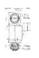
P 1951 o. E. WAGENKNECHT ETAL 2,567,585
VERNIER TUNING DIAL Filed June 30, 1949 Fig.2
OTTO EWAGENKNECHT GILBERT E. GUSTAFSON zzvmvrons.
THEIR ATTORN 3 the engagement between planetary gear 26 and gear H. The gears and 26 have a further pair of planetary gears 28 and 29 respectively fixed thereto and driven thereby, these latter gears meshing with a stationary crown gear 30. The crown gear 38 is mounted coaxially with the shaft I2 on a stationary bracket 3| which, in turn, is fixed to the housing II of the turret tuner ID. A drum 32 is mounted coaxially with the tuning shaft I2 and supported by the extremities of the second shaft 21 so that rotation of shaft I2 causes similar rotation of the drum 32. A cylindrical member 33 is also mounted coaxially with the shaft I2 and is supported on the receiver panel by means of screws passing through the mounting holes 34, or by other suitable means. The cylindrical member 33 has an aperture 35 formed therein, this aperture being covered by the clear plastic portion I9 of the actuating knob i8. opaque plastic and has channel-indicating indicia inscribed therein in clear transparent plastic about the periphery thereof to appear selectively under the aperture 35 as the drum rotates. ,the drum 32 so that the indicia may be illuminated and observed through the clear transparent plastic portion I9 and aperture 35. The electric lamp may be energized continuously while the receiver is in operation without adversely detracting from an observer's enjoyment of the images reproduced by the receiver reproducing device, since the drum 32 and aperture 35 are arranged so that the drum may be viewed only from directly above the dial.
In operation, rotation of the knob I8 causes the pinion 2| to drive the planetary gears 25 and 26 in opposite directions about the shaft 21. The gears 25 and 26, in turn, respectively rotate the gears 28 and 29 and these latter gears, due to their engagement with the stationary crown gear 30, cause the transverse shaft 21 to rotate about the longitudinal axis of the shaft l2, and, therefore cause the shaft 12 to rotate. In addition, the rotation of shaft 21 about the longitudinal axis of the shaft I2 causes the drum 32 similiarly to rotate about this axis whereby the various indicia inscribed about the periphery of the drum appear selectively under the aperture 35. A desired ratio between the rotation of the knob I8 and rotation of the shaft I2 is obtained by proper proportioning of the dimensions of the planetary gears 25, 26 and 28, 29. When desired the gears 28 and 29 may be eliminated and gears 25 and 26 directly coupled to the stationary crown gear 36, to provide a 2:1 ratio between knob and shaft rotation.
Figure 2 shows a further view of the tuning dial and illustrates the manner in which the planetary gears 28 and 29 mesh with the stationary crown gear 30 to cause the second shaft 21 to rotate about the longitudinal axis of the tuning shaft I2 when the planetary gears are driven by pinion gear 2| of Figure 1. As previously described, rotation of the shaft 21 about this axis causes corresponding rotation of the shaft I2 and coaxial drum 32.
Figure 3 shows a View of the coaxial drum 32 having numerals inscribed about its periphery and appropriately positioned so that they will lie under the aperture of the member 33 of Figure 1. These numerals are so arranged that when the actuating knob I8 is rotated to rotate the tuning shaft I2 against the action of the ball I5 and its associated detents these numerals selec- The drum 32 is constructed, preferably, of 2 An electric lamp may be placed inside i tively appear under the aperture 35 to indicate the various settings of the turret tuner as determined by the ball and detent arrangement. As previously pointed out, these numerals may be formed of clear transparent plastic so that they may be illuminated by an electric lamp placed within the drum.
It is apparent that the tuning dial of the present invention may be used in other apparatus apart from television receivers, such as radio receivers, car receivers and the like.
This invention provides, therefore, a compact tuning dial for controlling the tuning mechanism of a television receiver or the like in an improved and efiiclent manner.
While a particular embodiment of the invention has been shown and described modifications may be made therein, and it is intended in the appended claims to cover all such modifications as fall within the true spirit and scope of the invention.
We claim:
1. An indicating and actuating assembly for actuating a rotatable tuning shaft of a tuning mechanism of a television receiver or the like comprising: a pinion gear rotatably mounted in coaxial relation with said tuning shaft; a second shaft extending transversely to the longitudinal axis of said tuning shaft and mechanically coupled thereto for imparting rotational motion to said tuning shaft; a drum having channelindicating indicia inscribed thereon mounted coaxially with said tuning shaft and supported by the extremities of said second shaft; a stationarv crown gear supported coaxially with said tuning shaft; a planetary gear rotatably mounted on said second shaft in meshing engagement with said crown gear and mechanically coupled to said pinion gear to be rotated thereby; and an actuating knob for rotating said pinion gear to cause rotational motion of said second shaft and said drum about the longitudinal axis of said tuning shaft.
2. An indicating and actuating assembly for actuating a rotatable tuning shaft of a tuning mechanism of a television receiver or the like comprising: an actuating knob rotatably mounted on said tuning shaft; a pinion gear fixed to said knob in coaxial relation with said tuning shaft; a second shaft supported by and extending through said tuning shaft transversely to the longitudinal axis thereof; a stationary crown gear supported by said tuning mechanism coaxially with said tuning shaft; a first pair of planetar gears rotatably mounted on said second shaft at opposite extremities thereof in meshing engagement with said crown gear; a second pair of planetary gears rotatably mounted on said second shaft respectively coupled to said first pair and in meshing engagement with said pinion gear; and a drum having channel-indicating indicia inscribed thereon mounted coaxially with said tuning shaft and supported by the extremities of said second shaft.
' 3. An indicating and actuating assembly for actuating a rotatable tuning shaft of a tuning mechanism of a television receiver or the like comprising: a pinion gear rotatably mounted in coaxial relation with said tuning shaft; a second shaft supported by and extending through said tuning shaft transversely to the longitudinal axis thereof; a drum having channel-indicating indicia inscribed thereon mounted coaxially with said tuning shaft and supported by the extremities of said second shaft; a stationary crown gear supported coaxially with said tuning shaft; a planetary gear system rotatably mounted on said second shaft in meshing engagement with said crown gear and said pinion gear for imparting rotational motion from said pinion to said tuning shaft; a tubular housing mounted coaxially with said drum and having an aperture through which said indicia may be viewed; and an actuating knob for rotating said pinion gear and having a transparent cylindrical portion circumscribing said housing and forming a window over said I aperture.
REFERENCES CITED The following references are of record in the file of this patent:
UNITED STATES PATENTS Number
Priority Applications (1)
| Application Number | Priority Date | Filing Date | Title |
|---|---|---|---|
| US102352A US2567585A (en) | 1949-06-30 | 1949-06-30 | Vernier tuning dial |
Applications Claiming Priority (1)
| Application Number | Priority Date | Filing Date | Title |
|---|---|---|---|
| US102352A US2567585A (en) | 1949-06-30 | 1949-06-30 | Vernier tuning dial |
Publications (1)
| Publication Number | Publication Date |
|---|---|
| US2567585A true US2567585A (en) | 1951-09-11 |
Family
ID=22289404
Family Applications (1)
| Application Number | Title | Priority Date | Filing Date |
|---|---|---|---|
| US102352A Expired - Lifetime US2567585A (en) | 1949-06-30 | 1949-06-30 | Vernier tuning dial |
Country Status (1)
| Country | Link |
|---|---|
| US (1) | US2567585A (en) |
Cited By (4)
| Publication number | Priority date | Publication date | Assignee | Title |
|---|---|---|---|---|
| US2903894A (en) * | 1954-01-22 | 1959-09-15 | Legros Robert Guy | Method and apparatus for the transmission and reception of radio signals on a large number of regularly spaced frequencies |
| US3010336A (en) * | 1957-10-21 | 1961-11-28 | Gen Motors Corp | Gear mechanism |
| US4609894A (en) * | 1983-09-29 | 1986-09-02 | Citizen Watch Co., Ltd. | Tuning device |
| US20040055414A1 (en) * | 2000-07-14 | 2004-03-25 | Alessandro Toniolo | Knob with different gear ratios |
Citations (3)
| Publication number | Priority date | Publication date | Assignee | Title |
|---|---|---|---|---|
| US1392567A (en) * | 1919-05-05 | 1921-10-04 | Int Motor Co | Planetary driving-gear |
| US1801369A (en) * | 1922-08-21 | 1931-04-21 | William C Mccoy | Variometer dial |
| US2313183A (en) * | 1941-11-04 | 1943-03-09 | Trbojevich Nikola | Transmission and gear teeth |
-
1949
- 1949-06-30 US US102352A patent/US2567585A/en not_active Expired - Lifetime
Patent Citations (3)
| Publication number | Priority date | Publication date | Assignee | Title |
|---|---|---|---|---|
| US1392567A (en) * | 1919-05-05 | 1921-10-04 | Int Motor Co | Planetary driving-gear |
| US1801369A (en) * | 1922-08-21 | 1931-04-21 | William C Mccoy | Variometer dial |
| US2313183A (en) * | 1941-11-04 | 1943-03-09 | Trbojevich Nikola | Transmission and gear teeth |
Cited By (6)
| Publication number | Priority date | Publication date | Assignee | Title |
|---|---|---|---|---|
| US2903894A (en) * | 1954-01-22 | 1959-09-15 | Legros Robert Guy | Method and apparatus for the transmission and reception of radio signals on a large number of regularly spaced frequencies |
| US3010336A (en) * | 1957-10-21 | 1961-11-28 | Gen Motors Corp | Gear mechanism |
| US4609894A (en) * | 1983-09-29 | 1986-09-02 | Citizen Watch Co., Ltd. | Tuning device |
| USRE32853E (en) * | 1983-09-29 | 1989-01-31 | Citizen Watch Co., Ltd. | Tuning device |
| US20040055414A1 (en) * | 2000-07-14 | 2004-03-25 | Alessandro Toniolo | Knob with different gear ratios |
| US7044023B2 (en) * | 2000-07-14 | 2006-05-16 | Sit La Precisa S.P.A. | Knob with different gear ratios |
Similar Documents
| Publication | Publication Date | Title |
|---|---|---|
| US2567585A (en) | Vernier tuning dial | |
| US2537822A (en) | Spiral scanning mechanism | |
| US3886559A (en) | Remotely operated tv receiver antennae | |
| US3376846A (en) | Indicating apparatus | |
| GB1399264A (en) | Radio frequency tuners | |
| US3065728A (en) | Combined knob and dial | |
| US2575856A (en) | Spiral tuning device | |
| US3618406A (en) | Uhf tuner | |
| US2983248A (en) | Frequency-channel indicator | |
| GB1352817A (en) | Multi-turn potentiometer having a digital turns indicating device | |
| US2437306A (en) | Radio dial display device | |
| US3747420A (en) | Drive means for interval timer | |
| US3409748A (en) | Time switch device for a digital clock | |
| US3478718A (en) | Uhf-vhf channel indicating device | |
| US2128280A (en) | Remote radio control | |
| US3149607A (en) | Channel indicating device | |
| US3195402A (en) | Light spot projection apparatus | |
| US3240182A (en) | Fine tuning coupling apparatus for a television receiver | |
| US2861235A (en) | Servosystem control unit for antenna rotators | |
| US2219687A (en) | Selectively operable mechanism | |
| US3231190A (en) | Preset or predetermined type counter | |
| USRE23783E (en) | Demountable time switch unit fob | |
| US2738757A (en) | Frequency displays for a radio receiver or the like | |
| US4464794A (en) | Indicator device | |
| US2300020A (en) | Time switch |