US2563243A - Indoor television antenna - Google Patents
Indoor television antenna Download PDFInfo
- Publication number
- US2563243A US2563243A US92311A US9231149A US2563243A US 2563243 A US2563243 A US 2563243A US 92311 A US92311 A US 92311A US 9231149 A US9231149 A US 9231149A US 2563243 A US2563243 A US 2563243A
- Authority
- US
- United States
- Prior art keywords
- antenna
- inductors
- television
- discs
- switches
- Prior art date
- Legal status (The legal status is an assumption and is not a legal conclusion. Google has not performed a legal analysis and makes no representation as to the accuracy of the status listed.)
- Expired - Lifetime
Links
- 239000004020 conductor Substances 0.000 description 13
- 230000005540 biological transmission Effects 0.000 description 12
- 239000003990 capacitor Substances 0.000 description 12
- 244000045947 parasite Species 0.000 description 8
- 238000010276 construction Methods 0.000 description 6
- 230000008093 supporting effect Effects 0.000 description 5
- 230000000694 effects Effects 0.000 description 3
- 239000002184 metal Substances 0.000 description 3
- 230000001965 increasing effect Effects 0.000 description 2
- 230000003071 parasitic effect Effects 0.000 description 2
- 230000010287 polarization Effects 0.000 description 2
- 230000003321 amplification Effects 0.000 description 1
- 238000013016 damping Methods 0.000 description 1
- 238000010586 diagram Methods 0.000 description 1
- 230000001939 inductive effect Effects 0.000 description 1
- 238000000034 method Methods 0.000 description 1
- 238000003199 nucleic acid amplification method Methods 0.000 description 1
- 230000005855 radiation Effects 0.000 description 1
Images
Classifications
-
- H—ELECTRICITY
- H01—ELECTRIC ELEMENTS
- H01Q—ANTENNAS, i.e. RADIO AERIALS
- H01Q9/00—Electrically-short antennas having dimensions not more than twice the operating wavelength and consisting of conductive active radiating elements
- H01Q9/04—Resonant antennas
- H01Q9/06—Details
- H01Q9/14—Length of element or elements adjustable
-
- H—ELECTRICITY
- H01—ELECTRIC ELEMENTS
- H01Q—ANTENNAS, i.e. RADIO AERIALS
- H01Q9/00—Electrically-short antennas having dimensions not more than twice the operating wavelength and consisting of conductive active radiating elements
- H01Q9/04—Resonant antennas
- H01Q9/16—Resonant antennas with feed intermediate between the extremities of the antenna, e.g. centre-fed dipole
- H01Q9/28—Conical, cylindrical, cage, strip, gauze, or like elements having an extended radiating surface; Elements comprising two conical surfaces having collinear axes and adjacent apices and fed by two-conductor transmission lines
Definitions
- the present invention relates to an indoor antenna, and more particularly to an indoor television antenna which is readily oriented and tuned to a desired television channel.
- a still further object of the present invention is to provide an improved indoor antenna for television which is readily and efficiently adjusted or tuned to the desired television channel.
- Still another object of the present invention is to provide a compact, efficient and yet ornamental indoor television antenna.
- a still further object of the present invention is to provide an improved indoor television antenna which is readily oriented, quickly-tuned to a, desired television channel and also matched to the television receiver input.
- a still further object of the present invention is to provide an improved television antenna for indoor use which is readily adjusted or tuned to a desired television channel and yet provides adequate band width for each channel to be received.
- Fig. 1 is an electrical diagram of an indoor television antenna constructed in accordance with the principles of the present invention.
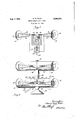
- Fig. 2 is a diagrammatic representation of the physical construction and contour of an antenna having the electrical circuit shown in Fig. l and also being provided with a parasite to increase the efficiency of the antenna.
- two parallel discs II and I2 are arranged in vertical :planes so as to be spaced apart several times the diameter of each disc.
- discs such as II and I2 of about 5 inches diameter spaced apart about 2 feet.
- the disc I I is provided with two relatively large conductors I3 and I4 which may be in the form of metal strips having an interconnecting portion I5, securely bonded to or in relatively intimate contact with the disc Il.
- This construction permits quick assembly since the two conductors I3 and I4 together with the interconnecting portion I5 may be formed of a single properly bent piece of strip metal.
- the other disc I2 likewise is Iprovided with large strip conductors I6 and I'I having an interconnecting portion I 8 rin intimate contact with the disc I2.
- an equipotential point is one where the potentials measured from the ends of the antenna to the point are equal in magnitude but opposite in phase.
- Each of the inductors I9 and 2l is tapped so that a switch 22 may select certain portions of the inductors thereby to vary the effective inductance between the conductors I3 and I6.
- the contacts of the switch 22 are connected to the movable contact of a switch 23 which is arranged to connect a selected one of a plurality of capacitors 24 between the taps of the inductors I9 and 2l.
- the movable contacts of the switches 22 and 23 are connected to the transmission line conductor indicated by the terminal 25.
- the terminal 25 shown in Fig. 1 constitutes a portion of a 300 ohm transmission line.
- Thevarious capacitors 24 are of different size so that together with the effective inductance of the inductors I9 and 2
- the antenna With the switches 22 and 23 at their topmost position as seen in Fig. 1, the antenna is arranged for the reception of television channel 2.
- the effective principal portion of the antenna consists of the two metal strips I3 and I6 leading to the discs I I and I2.
- the input impedance of these strips is equivalent to a high capacitive reactance in series with a small resistance.
- have sufcient inductance to tune out the capacitive reactance so as to leave substantially an equivalent impedance consisting of a small resistive and a slightly higher inductive component.
- the switch 23 includes a minimum amount of the inductors I and 2I, and that the switch 22 is connected directly'to the conductors I4 and Il.
- the present antenna at the higher frequency television channels has a characteristic somewhat approaching a double cone antenna with end loading. This characteristic produces substantially 30) ohms input impedance without the need of inductors and a capacitor. It has been found that the present antenna has a standing wave ratio for each channel position in the lower frequency band which ranges from 8 to 1 at the extremities of the channel to 1 to 1 at the center of the ⁇ channel which is being received.
- An antenna structure such as that illustrated by the electrical circuit in Fig. 1 is provided with one control knob which actuates the switches 22 and 23.
- This control knob for the switch is located at an equipotential point so as to eliminate the effect ol hand capacity.
- a cylindrical non-conductive housing supports the antenna elements. The housing is journaled for rotation about a vertical axis passing through ⁇ the equipotential Zone.
- a suitable control knob is provided at the top of the cylindrical housing.
- a commercial embodiment such as that just described is similar to the lower portion of the arrangement illustrated in Fig. 2 wherein the antenna elements are contained within a cylindrical housing 2l carried by a support member 28.
- the support member 28 is arranged for rotation upon a base 29.
- a A suitable control knob 3l kis provided for the actuation of the switches 22 and 23.
- Another control knob shown is located at right angles to the knob 3
- the arrangement illustrated in Fig. 2 also shows ⁇ how an antenna of this type may be employed with a parasite. It is known that a parasite is of benefit at spacing of the order of onetenth of one wave length. If the parasite has antenna elements corresponding to the antenna shown in the lower portion of Fig. 2 it may be tuned by selector switches 35 and 34 connected to a short circuit instead of a transmission line. lIhe two selector switches 33 and 34 are connected to the selector switches 22 and 23 so that the control knob 3l serves to actuate all switches.
- the elements of the parasite antenna may be contained within a similar cylindrical housing 35 supported by an interconnecting member 3d engaging the top of the cylindrical housing 2'! of the antenna proper.
- the housing 35 of the parasite may be provided with a control knob 31 whereby the antenna and the parasite both may be oriented.
- the antenna structure may be tilted so as to be rotatable about a Vertical aXis passing through the equipotential Zone but the axis of rotation need not necessarily be perpendicular to the longitudinal aXis of the antenna. It furthermore will be appreciated that where the antenna is employed in this manner it may be just as convenient to match the impedance of the antenna to the input of the receiver or the input of the first stage of amplification and that the tuning of the antenna may be accomplished simultaneously with the tuning of the input circuit of the receiver.
- An indoor antenna for television reception comprising two parallel discs spaced apart a distance equal to several diameters of said discs, a pair of tapped inductors located betweensaid discs adjacent an equipotential point, one terminal of each inductor being connected to an adjacent disc by a relatively large generally horizontal conductor, a transmission line, a plurality of switches interconnecting said tapped inductors with said line, and a plurality of capacitors adapted to be selectively connected between said inductors by said switches.
- An indoor antenna for television reception comprising two parallel discs spaced apart a distance equal to several diameters of said discs, a pair of tapped inductors located on a line between said discs adjacent an equipotential point, one terminal of each inductor being connected to an adjacent disc by a relatively large generally horizontal conductor, a transmission line, a plurality of switches interconnecting said tapped inductors with said line, a plurality of resistors connected between one of said switches and certain taps on one of said inductors, and a plurality of capacitors adapted to be selectively connected between said inductors by said switches.
- An indoor antenna for television comprising two parallel vertical conductive discs, a pair of inductors located on a line between said discs adjacent an equipotential point, one terminal of each inductor being connected to an adjacent disc by means of a relatively large conductor, means ,for varying the eiective amount of inductance of each of said inductors in accordance with a television channel to be received, means for broad banding said antenna at the lower television channels, a transmission line connected to said inductors, and switching means for connecting a capacitor between said inductors to provide an impedance value for said antenna substantially equal to the impedance value of said transmission line.
- the combination comprising an indoor antenna for television reception having spaced apart parallel vertical conductive discs, a pair of inductors located horizontally between said discs adjacent an equipotential point, one terminal of each inductor being connected to an adjacent disc, means for varying the effective amount of inductance associated with each disc for a selected television channel to compensate for the capacitive reactance of said antenna, a transmission line4 connected to said inductors and means for connecting a capacitor between said inductors to provide an impedance value for said antenna substantially equal to the impedance of said transmission line, and a parasitic antenna arranged parallel to said rst antenna and comprising spaced apart parallel vertical conductive discs, a pair of inductors located horizontally between said discs adjacent an equipotential point, one terminal of each inductor being connected to an adjacent disc, means for varying the effective amount of inductance associated with each disc for a selected television channel, means for connecting a capacitor between said inductors to provide an impedance Value corresponding to that of said first antenna, and means for simultaneously
- An indoor antenna for television comprising a housing supporting two parallel vertical conductive discs, a pair of inductors located between said discs adjacent an equipotential point, one terminal of each inductor being connected to an adjacent disc by means of a relatively large conductor, means for varying the effective amount of inductance of each of said inductors in accordance with television channels to be received, means for broad-banding said antenna at the lower television channels, a transmission line connected to said inductors, and means for connecting a capacitor between said inductors to provide an impedance value for said antenna substantially equal to the impedance value of said transmission line, and a parasitic antenna having a housing arranged parallel to said first 6 housing and supporting two parallel vertical conductive discs, a pair of inductors located between said discs adjacent an equipotential point, one terminal of each inductor being connected to an adjacent disc by means of a relatively large conductor, means for varying the eiective amount of inductance of each of said inductors in accordance with television channels to be received, means
- An indoor antenna system for television reception comprising ahorizontal housing sup porting two parallel discs spaced apart a distance equal to several diameters of said discs, a pair of tapped inductors located between said discs adjacent an equipotential point, one ter-- minal of each inductor being connected to an adjacent disc by a relatively large conductor, a transmission line, a plurality of rotary switches interconnecting said tapped inductors with saidr line, a plurality of resistors connected between the contacts of one of said switches and certain taps on one of said inductors, a plurality of capacitors adapted to be selectively connected between said inductors by said switches, and a second housing located parallel to and above said first housing and supporting two parallel discs spaced apart a distance equal to several diameters of said discs, a pair of tapped inductors located between said discs adjacent an equipotential point, one terminal of each inductor being connected to an adjacent disc by a relatively large conductor, a plurality of rotary switches interconnect
Landscapes
- Variable-Direction Aerials And Aerial Arrays (AREA)
Description
Patented Aug. 7, 1951 INDOOR TELEVISION ANTENNA Elmer G. Hills, Chicago, Ill., assignor of one-half to Joseph N. Marks, Julius Tunkl, I. Rosenthal, and E. Lichtenstein, a partnership doing business as Tricraft Products Co., Chicago, Ill.
Application May 10, 1949, `Serial No. 92,311
(Cl. Z50-33) 6 Claims.
The present invention relates to an indoor antenna, and more particularly to an indoor television antenna which is readily oriented and tuned to a desired television channel.
With the increasing popularity of television in congested areas it has been found impractical or 'diicult to erect on apartment houses and other structures an individual antenna for each television receiver. Accordingly, it has been proposed to employ indoor television antennas. One of the most common indoor television antennas consists of two telescopic rods which must be adjusted to resonance and then oriented for proper direction and polarization. Generally, the adjustment to resonance is obtained by a trial and error method which is complicated by hand capacity. Such antennas, however, generally cannot be adjusted to the lowest frequency television channel since this would make the size of the antenna. too great. The great size would be objectionable because of its appearance and also because of the difficulty of orienting a device having an overall length of the order of 108 inches. Such type antenna furthermore produces a mismatch when used with a 300 ohm receiver input.
It, therefore, would be desirable to provide an improved indoor antenna which is readily adjusted to resonance and conveniently oriented for direction and polarization. In accordance with the present invention this may Hoe accomplished by a unique antenna construction which is contained within an ornamental housing having an overall length of the order of 2 feet.
It, therefore, is an object of the present invention to provide an improved indoor antenna which is readily oriented.
A still further object of the present invention is to provide an improved indoor antenna for television which is readily and efficiently adjusted or tuned to the desired television channel.
Still another object of the present invention is to provide a compact, efficient and yet ornamental indoor television antenna.
A still further object of the present invention is to provide an improved indoor television antenna which is readily oriented, quickly-tuned to a, desired television channel and also matched to the television receiver input.
A still further object of the present invention is to provide an improved television antenna for indoor use which is readily adjusted or tuned to a desired television channel and yet provides adequate band width for each channel to be received.
Other and further objects of the present inventionsubsequently will become apparent by reference to the following description taken in conjunction with the accompanying drawings wherein:
Fig. 1 is an electrical diagram of an indoor television antenna constructed in accordance with the principles of the present invention; and
Fig. 2 is a diagrammatic representation of the physical construction and contour of an antenna having the electrical circuit shown in Fig. l and also being provided with a parasite to increase the efficiency of the antenna.
Referring to Fig. 1 of the drawing it will be noted that two parallel discs II and I2 are arranged in vertical :planes so as to be spaced apart several times the diameter of each disc. In one construction it was found expedient to use discs such as II and I2 of about 5 inches diameter spaced apart about 2 feet. The disc I I is provided with two relatively large conductors I3 and I4 which may be in the form of metal strips having an interconnecting portion I5, securely bonded to or in relatively intimate contact with the disc Il. This construction permits quick assembly since the two conductors I3 and I4 together with the interconnecting portion I5 may be formed of a single properly bent piece of strip metal. The other disc I2 likewise is Iprovided with large strip conductors I6 and I'I having an interconnecting portion I 8 rin intimate contact with the disc I2.
Connected in the proximity of an equipotential point between the strips I3 and I6 are a plurality of inductors I9 and 2l. An equipotential point is one where the potentials measured from the ends of the antenna to the point are equal in magnitude but opposite in phase. Each of the inductors I9 and 2l is tapped so that a switch 22 may select certain portions of the inductors thereby to vary the effective inductance between the conductors I3 and I6. The contacts of the switch 22 are connected to the movable contact of a switch 23 which is arranged to connect a selected one of a plurality of capacitors 24 between the taps of the inductors I9 and 2l. The movable contacts of the switches 22 and 23 are connected to the transmission line conductor indicated by the terminal 25. For use with present Vday television receivers the terminal 25 shown in Fig. 1 constitutes a portion of a 300 ohm transmission line. Y
Thevarious capacitors 24 are of different size so that together with the effective inductance of the inductors I9 and 2| the proper impedance relation will result to match the antenna to the 300 ohm output terminal 25.
With the switches 22 and 23 at their topmost position as seen in Fig. 1, the antenna is arranged for the reception of television channel 2. In this position of the switches the effective principal portion of the antenna consists of the two metal strips I3 and I6 leading to the discs I I and I2. The input impedance of these strips is equivalent to a high capacitive reactance in series with a small resistance. The two coils I9 and 2| have sufcient inductance to tune out the capacitive reactance so as to leave substantially an equivalent impedance consisting of a small resistive and a slightly higher inductive component.
It will be noted from Fig. 1 that the taps oi the inductor 2l at the higher inductance values are connected through resistors 2B to the contact points of the switch 22. At the lower frequency the resistors 26 Vare introduced for a damping effect to increase the band width. While Vthe introduction of resistors would indicate a reduction in the antenna eliciency it has been found that the values of the resistors employed are not as great as was expected based upon calculations made with the aid of known formula. It was thought that the present construction difering from conventional antenna construction 'and configuration might be due to an inherent higher radiation resistance.
It also will be noted from Fig. l that at the highest channel to be received the switch 23 includes a minimum amount of the inductors I and 2I, and that the switch 22 is connected directly'to the conductors I4 and Il. The present antenna at the higher frequency television channels has a characteristic somewhat approaching a double cone antenna with end loading. This characteristic produces substantially 30) ohms input impedance without the need of inductors and a capacitor. It has been found that the present antenna has a standing wave ratio for each channel position in the lower frequency band which ranges from 8 to 1 at the extremities of the channel to 1 to 1 at the center of the `channel which is being received.
An antenna structure such as that illustrated by the electrical circuit in Fig. 1 is provided with one control knob which actuates the switches 22 and 23. In a commercial embodiment the switch knob-had positions for channels 2, 3. 4, 5, 6 and one position for channels '7 to 13.
This control knob for the switch is located at an equipotential point so as to eliminate the effect ol hand capacity. A cylindrical non-conductive housing supports the antenna elements. The housing is journaled for rotation about a vertical axis passing through `the equipotential Zone. A suitable control knob is provided at the top of the cylindrical housing.
A commercial embodiment such as that just described is similar to the lower portion of the arrangement illustrated in Fig. 2 wherein the antenna elements are contained within a cylindrical housing 2l carried by a support member 28. The support member 28 is arranged for rotation upon a base 29.a A suitable control knob 3l kis provided for the actuation of the switches 22 and 23. Another control knob shown is located at right angles to the knob 3| whereby the cylindrical housing 2'I may be rotated about its vertical axis which passes through the support 28 at the base 29.
The arrangement illustrated in Fig. 2 also shows` how an antenna of this type may be employed with a parasite. It is known that a parasite is of benefit at spacing of the order of onetenth of one wave length. If the parasite has antenna elements corresponding to the antenna shown in the lower portion of Fig. 2 it may be tuned by selector switches 35 and 34 connected to a short circuit instead of a transmission line. lIhe two selector switches 33 and 34 are connected to the selector switches 22 and 23 so that the control knob 3l serves to actuate all switches. The elements of the parasite antenna may be contained within a similar cylindrical housing 35 supported by an interconnecting member 3d engaging the top of the cylindrical housing 2'! of the antenna proper. The housing 35 of the parasite may be provided with a control knob 31 whereby the antenna and the parasite both may be oriented.
From Fig. 2 it will be noted that the parasite operates neither as a director nor a renector but still has the effect of obtaining increased gain and directivity. Such an arrangement provides the'most convenient assembly which is readily employed within the home.
In the arrangement thus far described it has been assumed that it is preferable to orient the antenna structure in a horizontal plane. Where an antenna of this type, however, is to be employed within the television receiver cabinet the antenna structure may be tilted so as to be rotatable about a Vertical aXis passing through the equipotential Zone but the axis of rotation need not necessarily be perpendicular to the longitudinal aXis of the antenna. It furthermore will be appreciated that where the antenna is employed in this manner it may be just as convenient to match the impedance of the antenna to the input of the receiver or the input of the first stage of amplification and that the tuning of the antenna may be accomplished simultaneously with the tuning of the input circuit of the receiver. It, therefore, will be appreciated that while for the purpose of illustrating and describing the present invention certain preferred embodiments have been mentioned in the description and certain arrangements have been illustrated in the drawings, that the invention is not to be limited there-- by since such variations in the arrangement of the components and their relative values are contemplated as may be commensurate with thc spirit and scope of the invention as set forth in the accompanying claims.
What I desire to protect by United States Letters Patent is claimed as follows:
1. An indoor antenna for television reception comprising two parallel discs spaced apart a distance equal to several diameters of said discs, a pair of tapped inductors located betweensaid discs adjacent an equipotential point, one terminal of each inductor being connected to an adjacent disc by a relatively large generally horizontal conductor, a transmission line, a plurality of switches interconnecting said tapped inductors with said line, and a plurality of capacitors adapted to be selectively connected between said inductors by said switches.
2. An indoor antenna for television reception comprising two parallel discs spaced apart a distance equal to several diameters of said discs, a pair of tapped inductors located on a line between said discs adjacent an equipotential point, one terminal of each inductor being connected to an adjacent disc by a relatively large generally horizontal conductor, a transmission line, a plurality of switches interconnecting said tapped inductors with said line, a plurality of resistors connected between one of said switches and certain taps on one of said inductors, and a plurality of capacitors adapted to be selectively connected between said inductors by said switches.
3. An indoor antenna for television comprising two parallel vertical conductive discs, a pair of inductors located on a line between said discs adjacent an equipotential point, one terminal of each inductor being connected to an adjacent disc by means of a relatively large conductor, means ,for varying the eiective amount of inductance of each of said inductors in accordance with a television channel to be received, means for broad banding said antenna at the lower television channels, a transmission line connected to said inductors, and switching means for connecting a capacitor between said inductors to provide an impedance value for said antenna substantially equal to the impedance value of said transmission line.
4. The combination comprising an indoor antenna for television reception having spaced apart parallel vertical conductive discs, a pair of inductors located horizontally between said discs adjacent an equipotential point, one terminal of each inductor being connected to an adjacent disc, means for varying the effective amount of inductance associated with each disc for a selected television channel to compensate for the capacitive reactance of said antenna, a transmission line4 connected to said inductors and means for connecting a capacitor between said inductors to provide an impedance value for said antenna substantially equal to the impedance of said transmission line, and a parasitic antenna arranged parallel to said rst antenna and comprising spaced apart parallel vertical conductive discs, a pair of inductors located horizontally between said discs adjacent an equipotential point, one terminal of each inductor being connected to an adjacent disc, means for varying the effective amount of inductance associated with each disc for a selected television channel, means for connecting a capacitor between said inductors to provide an impedance Value corresponding to that of said first antenna, and means for simultaneously controlling said means for varying the effective amount of inductance of said two pairs of inductors.
5. An indoor antenna for television comprising a housing supporting two parallel vertical conductive discs, a pair of inductors located between said discs adjacent an equipotential point, one terminal of each inductor being connected to an adjacent disc by means of a relatively large conductor, means for varying the effective amount of inductance of each of said inductors in accordance with television channels to be received, means for broad-banding said antenna at the lower television channels, a transmission line connected to said inductors, and means for connecting a capacitor between said inductors to provide an impedance value for said antenna substantially equal to the impedance value of said transmission line, and a parasitic antenna having a housing arranged parallel to said first 6 housing and supporting two parallel vertical conductive discs, a pair of inductors located between said discs adjacent an equipotential point, one terminal of each inductor being connected to an adjacent disc by means of a relatively large conductor, means for varying the eiective amount of inductance of each of said inductors in accordance with television channels to be received, means for connecting a capacitor between said inductors to provide a desired impedance value, and means for simultaneously controlling said means for varying the effective amount of inductance of each of said inductors.
6. An indoor antenna system for television reception comprising ahorizontal housing sup porting two parallel discs spaced apart a distance equal to several diameters of said discs, a pair of tapped inductors located between said discs adjacent an equipotential point, one ter-- minal of each inductor being connected to an adjacent disc by a relatively large conductor, a transmission line, a plurality of rotary switches interconnecting said tapped inductors with saidr line, a plurality of resistors connected between the contacts of one of said switches and certain taps on one of said inductors, a plurality of capacitors adapted to be selectively connected between said inductors by said switches, and a second housing located parallel to and above said first housing and supporting two parallel discs spaced apart a distance equal to several diameters of said discs, a pair of tapped inductors located between said discs adjacent an equipotential point, one terminal of each inductor being connected to an adjacent disc by a relatively large conductor, a plurality of rotary switches interconnecting said tapped inductors with a plurality of capacitors, a plurality of resistors connected between the contacts of one of said switches and certain taps on one of said inductors, and means for simultaneously actuating all of said switches of both of said supporting structures.
ELMER G. HILLS.
REFERENCES CITED The following references are of record in the file of this patent:
UNITED STATES PATENTS Number Name Date 2,177,416 Alford Oct. 24, 1939 2,272,608 Hoffman Feb. 10, 1942 2,293,112 Carlson et al Aug. 18, 1942 2,311,364 Buschbeck et al Feb. 16, 1943 2,313,046 Bruce Mar. 9, 1943 2,324,462 Leeds et al July 13, 1943 2,356,201 Beers Aug. 22, 1944 2,387,116 Bruce Oct. 16, 1945 2,419,577 Libby Apr. 29, 1947 2,492,989 Halstead Jan. 3, 1950 OTHER REFERENCES QST. for April 1933, page 21.
Priority Applications (1)
| Application Number | Priority Date | Filing Date | Title |
|---|---|---|---|
| US92311A US2563243A (en) | 1949-05-10 | 1949-05-10 | Indoor television antenna |
Applications Claiming Priority (1)
| Application Number | Priority Date | Filing Date | Title |
|---|---|---|---|
| US92311A US2563243A (en) | 1949-05-10 | 1949-05-10 | Indoor television antenna |
Publications (1)
| Publication Number | Publication Date |
|---|---|
| US2563243A true US2563243A (en) | 1951-08-07 |
Family
ID=22232642
Family Applications (1)
| Application Number | Title | Priority Date | Filing Date |
|---|---|---|---|
| US92311A Expired - Lifetime US2563243A (en) | 1949-05-10 | 1949-05-10 | Indoor television antenna |
Country Status (1)
| Country | Link |
|---|---|
| US (1) | US2563243A (en) |
Cited By (14)
| Publication number | Priority date | Publication date | Assignee | Title |
|---|---|---|---|---|
| US2585670A (en) * | 1951-10-19 | 1952-02-12 | Marvin P Middlemark | Television and high-frequency antenna systems |
| US2666138A (en) * | 1950-05-25 | 1954-01-12 | Radiart Corp | Antenna |
| US2686873A (en) * | 1952-04-01 | 1954-08-17 | Rca Corp | Built-in cabinet antenna for television receivers |
| US2724773A (en) * | 1951-10-16 | 1955-11-22 | Hi Lo Tv Antenna Corp | Antennas |
| US2932822A (en) * | 1954-10-25 | 1960-04-12 | Hills Elmer Guy | Television antenna having adjustable tuning network |
| US2978703A (en) * | 1960-03-08 | 1961-04-04 | Avco Corp | Folded dipole antenna fabricated from a single metallic sheet |
| US3210766A (en) * | 1962-02-15 | 1965-10-05 | Ralph O Parker | Slot type antenna with tuning circuit |
| US3761934A (en) * | 1972-05-08 | 1973-09-25 | Dx Antenna | Two-element receiving antenna with critically spaced end sections |
| US4201990A (en) * | 1975-04-21 | 1980-05-06 | Hustler, Inc. | Tunable dipole antenna |
| US4207574A (en) * | 1978-09-08 | 1980-06-10 | Toia Michael J | Portable dipole antenna with end loading |
| US4835542A (en) * | 1988-01-06 | 1989-05-30 | Chu Associates, Inc. | Ultra-broadband linearly polarized biconical antenna |
| US5027128A (en) * | 1990-01-18 | 1991-06-25 | Blaese Herbert R | Inside window antenna |
| US5168279A (en) * | 1991-06-12 | 1992-12-01 | Hewlett-Packard Company | Antenna for sensing stray rf radiation |
| WO2002097918A1 (en) * | 2001-05-30 | 2002-12-05 | Ads Corporation | Low profile antenna |
Citations (10)
| Publication number | Priority date | Publication date | Assignee | Title |
|---|---|---|---|---|
| US2177416A (en) * | 1938-03-15 | 1939-10-24 | Mackay Radio & Telegraph Compa | Short wave antenna system |
| US2272608A (en) * | 1939-12-19 | 1942-02-10 | Internat Telephone Dev Co Inc | Antenna matching structure |
| US2293112A (en) * | 1939-08-31 | 1942-08-18 | Rca Corp | Compact high frequency dipole |
| US2311364A (en) * | 1939-04-03 | 1943-02-16 | Buschbeck Werner | Broad-band antenna |
| US2313046A (en) * | 1942-03-26 | 1943-03-09 | Bruce Malcolm | Radio antenna system |
| US2324462A (en) * | 1941-11-15 | 1943-07-13 | Gen Electric | High frequency antenna system |
| US2356201A (en) * | 1942-02-12 | 1944-08-22 | Rca Corp | Frequency modulation signal receiving system |
| US2387116A (en) * | 1944-04-08 | 1945-10-16 | Richard W Taylor | Radio antenna system |
| US2419577A (en) * | 1945-03-12 | 1947-04-29 | Standard Telephones Cables Ltd | Antenna system |
| US2492989A (en) * | 1946-02-09 | 1950-01-03 | Farnsworth Res Corp | Directive ultra high frequency antenna |
-
1949
- 1949-05-10 US US92311A patent/US2563243A/en not_active Expired - Lifetime
Patent Citations (10)
| Publication number | Priority date | Publication date | Assignee | Title |
|---|---|---|---|---|
| US2177416A (en) * | 1938-03-15 | 1939-10-24 | Mackay Radio & Telegraph Compa | Short wave antenna system |
| US2311364A (en) * | 1939-04-03 | 1943-02-16 | Buschbeck Werner | Broad-band antenna |
| US2293112A (en) * | 1939-08-31 | 1942-08-18 | Rca Corp | Compact high frequency dipole |
| US2272608A (en) * | 1939-12-19 | 1942-02-10 | Internat Telephone Dev Co Inc | Antenna matching structure |
| US2324462A (en) * | 1941-11-15 | 1943-07-13 | Gen Electric | High frequency antenna system |
| US2356201A (en) * | 1942-02-12 | 1944-08-22 | Rca Corp | Frequency modulation signal receiving system |
| US2313046A (en) * | 1942-03-26 | 1943-03-09 | Bruce Malcolm | Radio antenna system |
| US2387116A (en) * | 1944-04-08 | 1945-10-16 | Richard W Taylor | Radio antenna system |
| US2419577A (en) * | 1945-03-12 | 1947-04-29 | Standard Telephones Cables Ltd | Antenna system |
| US2492989A (en) * | 1946-02-09 | 1950-01-03 | Farnsworth Res Corp | Directive ultra high frequency antenna |
Cited By (16)
| Publication number | Priority date | Publication date | Assignee | Title |
|---|---|---|---|---|
| US2666138A (en) * | 1950-05-25 | 1954-01-12 | Radiart Corp | Antenna |
| US2724773A (en) * | 1951-10-16 | 1955-11-22 | Hi Lo Tv Antenna Corp | Antennas |
| US2585670A (en) * | 1951-10-19 | 1952-02-12 | Marvin P Middlemark | Television and high-frequency antenna systems |
| US2686873A (en) * | 1952-04-01 | 1954-08-17 | Rca Corp | Built-in cabinet antenna for television receivers |
| US2932822A (en) * | 1954-10-25 | 1960-04-12 | Hills Elmer Guy | Television antenna having adjustable tuning network |
| US2978703A (en) * | 1960-03-08 | 1961-04-04 | Avco Corp | Folded dipole antenna fabricated from a single metallic sheet |
| US3210766A (en) * | 1962-02-15 | 1965-10-05 | Ralph O Parker | Slot type antenna with tuning circuit |
| US3761934A (en) * | 1972-05-08 | 1973-09-25 | Dx Antenna | Two-element receiving antenna with critically spaced end sections |
| US4201990A (en) * | 1975-04-21 | 1980-05-06 | Hustler, Inc. | Tunable dipole antenna |
| US4207574A (en) * | 1978-09-08 | 1980-06-10 | Toia Michael J | Portable dipole antenna with end loading |
| US4835542A (en) * | 1988-01-06 | 1989-05-30 | Chu Associates, Inc. | Ultra-broadband linearly polarized biconical antenna |
| US5027128A (en) * | 1990-01-18 | 1991-06-25 | Blaese Herbert R | Inside window antenna |
| US5168279A (en) * | 1991-06-12 | 1992-12-01 | Hewlett-Packard Company | Antenna for sensing stray rf radiation |
| WO2002097918A1 (en) * | 2001-05-30 | 2002-12-05 | Ads Corporation | Low profile antenna |
| US6518933B2 (en) * | 2001-05-30 | 2003-02-11 | Ads Corporation | Low profile antenna |
| US20060176231A1 (en) * | 2001-05-30 | 2006-08-10 | Pecora Ronald A Jr | Low profile antenna |
Similar Documents
| Publication | Publication Date | Title |
|---|---|---|
| US2563243A (en) | Indoor television antenna | |
| US4193077A (en) | Directional antenna system with end loaded crossed dipoles | |
| US2558487A (en) | Multifrequency tunable antenna | |
| US2495579A (en) | Antenna | |
| US2967300A (en) | Multiple band antenna | |
| US2759098A (en) | Printed circuit band switching television tuner | |
| US2414280A (en) | Variometer | |
| US2631241A (en) | Tuning device for high-frequency electrical energy | |
| US2715211A (en) | Ultra high frequency tuning systems | |
| US2143658A (en) | Ultra short wave system | |
| US2584176A (en) | Television tuner | |
| US2629860A (en) | Inductance tuning unit | |
| US2932822A (en) | Television antenna having adjustable tuning network | |
| US2601445A (en) | Ultrahigh-frequency structure | |
| US2772355A (en) | Wide range tuner | |
| US2554295A (en) | Variable inductance device | |
| US2734175A (en) | Wasmansdorff | |
| US3604007A (en) | Combined television stand and antenna system | |
| US2913681A (en) | Sleeve-tuned band-pass tuner with variable coupling | |
| US2496322A (en) | Tuning system | |
| US2240849A (en) | Band-pass filter | |
| US2802946A (en) | Ultrahigh-frequency converter | |
| US1959407A (en) | Transmission system | |
| US2312211A (en) | Tuning system | |
| US2700730A (en) | Mixer injection |