US2561663A - Control means for dental engines and the like - Google Patents
Control means for dental engines and the like Download PDFInfo
- Publication number
- US2561663A US2561663A US760816A US76081647A US2561663A US 2561663 A US2561663 A US 2561663A US 760816 A US760816 A US 760816A US 76081647 A US76081647 A US 76081647A US 2561663 A US2561663 A US 2561663A
- Authority
- US
- United States
- Prior art keywords
- dental
- valve
- tool
- engine
- pneumatic
- Prior art date
- Legal status (The legal status is an assumption and is not a legal conclusion. Google has not performed a legal analysis and makes no representation as to the accuracy of the status listed.)
- Expired - Lifetime
Links
Images
Classifications
-
- A—HUMAN NECESSITIES
- A61—MEDICAL OR VETERINARY SCIENCE; HYGIENE
- A61C—DENTISTRY; APPARATUS OR METHODS FOR ORAL OR DENTAL HYGIENE
- A61C1/00—Dental machines for boring or cutting ; General features of dental machines or apparatus, e.g. hand-piece design
- A61C1/0007—Control devices or systems
Definitions
- This invention relates, as indicated, to control means for dental engines and the like, and more particularly to a foot-operated control device of a type adapted to permit considerable freedom of movement on the part of the operator.
- Another object of my invention is to provide such control means which will be rendered inoperative to start the engine when the dental tool or the like is suspended from its usual support.
- Fig. 1 is a general perspective view of a dental chair and dental engine associated therewith showing a preferred arrangement of my new control device;
- Fig. 2 is a diagrammatic layout of one embodiment of my invention employing an electric circuit as an element of the control means; and. r
- T Fig. 3. is another such diagrammatic layout ofa system which is pneumatic throughout.
- the master switch I of the motor controlling circuit for electric motorZ is installed in the base of dental column 3 in the manner explained in my aforesaid co-pending application, master switch I corresponding to switch 16 of such application.
- Master switch I is a normally open micro-switch'adapted to be operated by move ment of diaphragm 4 in response to pneumatic pressure in chamber 5.
- Chamber 5 is con nected to a resilient elongated tubular member 6 ordinarily of rubber and sealed at its other end to form a closed system.
- Such tubular member will preferably be arcuately disposed around the base 1 of the dental chair 8 and may lie beneath the rubber mat 9 ordinarily placed around such base.
- Thetool such as dental drill l0 mounted on theend of jointed boom II is supported when not in use by hook I2 carried by an upper extension of column 3.
- hook may be pivotally mounted to operate a switch in an electric circuit. controlling the operation of the motor.
- the present invention is concerned with means for controlling the pneumatic system itself.
- a valve [3 is provided in tubular member 6 communicating with the outer atmosphere.
- An armature I4 is pivoted at [5 to be rocked upon energization of solenoid 16, to close valve l3.
- spring I! acts on the armature to force valve I3 open.
- Valve I3 may, for example, be an ordinary automobile tire valve.
- the energization of the solenoid is controlled by switch l8 in the upper end of the dental column. Contact member IQ of such switch is forced open by the end of pivoted hook member I 2 when the dental tool is hung upon such hook, as shown in solid lines in Fig. 2.
- solenoid IE will not be energized and valve I3 will be held open so that tubular member 6 is in communication with the outer atmosphere. Foot pressure upon such tubular member, therefore, will be ineffective to operate master switch I when the dental tool is supported upon hook [2.
- spring 20 is effective to move the hook into dotted line position, as shown in Fig. 2, and spring contact member [9 moves to close switch l8 and activate solenoid "5, thereby closing valve 13.
- operation of the dental engine may be initiated and controlled by means of foot pressure on memher 6, as taught in my aforesaid co-pending application.
- the air entrapped in the pneumatic system will normally be under the same pressure as the outer atmosphere so that micro-switch I may be set for sensitive response to actuation of diaphragm 4.
- which may be of metal or thick-walled rubber pressure hose is in communication with resilient tubular member 6 and terminates in the upper end of column 3 in a valve 22 which may be of the same type as valve [3, for example.
- spring will, of course, be effective to rock such hook out of engagement with valve 22.
- rotation of the latter will be effective to open valve 22 and place tubular member 6 in communication with the outer atmosphere. It will be seen therefore that foot pressure on member 6 will be ineffective to operate master switch!
- control means for dental engines and the like employing a pneumatic system in which. ambient temperature and pressure chan es are automatically compensated for, and which is rendered inoperative when the tool connected to such engine has been hung upon its. supporting means.
- a dental engine including an electric motor, a power operated tool adapted to be driven by said engine, a movable support for said tool when not in, use, pneumatic pressure means operative to control operation of said engine, a normally open valve adapted to vent said pneumatic pressure means to render the same inoperative, an electric circuit including a solenoid operative upon energization to close said valve, and a switch in said circuit held open by said movable support only when said tool is resting thereon.
- a dental engine including an electric motor, a power operated tool adapted to be driven by said engine, a movable support for said tool adapted to be held in one position when said tool is thereon and to move to another position when said tool is removed therefrom, pneumatic pressure means operative to control operation of said engine, said pneumatic pressure means including a normally open valve as a vent therefor, mechanism adapted to operate said valve, and means operative by said support to control said mechanism.
- a dental engine including an electric motor
- a power operated tool adapted to be driven by said engine, a movable support for said tool when not in use, pneumatic pressure means operative to control operation of said engine, said pneu-v matic pressure means including a normally open valve as a vent therefor, mechanism adapted ta close said valve including a solenoid, an electric circuit for said solenoid, and a switch in said circuit operative by said movable support.
- a dental engine including an electric motor
- a power operated tool adapted to be driven by said engine, a movable support for said tool, pneumatic pressure means operative to control opera tion of said engine, said pressure pneumatic means including a valve, means in said valve normally holding said valve open to thereby vent said pneumatic pressure means, mechanism 09- erable to overcome the action of said latter means, to close said valve, and means operable by said support to actuate said mechanism.
Landscapes
- Health & Medical Sciences (AREA)
- Engineering & Computer Science (AREA)
- Water Supply & Treatment (AREA)
- Oral & Maxillofacial Surgery (AREA)
- Dentistry (AREA)
- Epidemiology (AREA)
- Life Sciences & Earth Sciences (AREA)
- Animal Behavior & Ethology (AREA)
- General Health & Medical Sciences (AREA)
- Public Health (AREA)
- Veterinary Medicine (AREA)
- Dental Tools And Instruments Or Auxiliary Dental Instruments (AREA)
Description
y 1951 H. M. KECKLEY 2,561,663
CONTROL MEANS FOR DENTAL ENGINES AND THE LIKE I Filed July 14, 1947 )r 1 WI/$7 A TTU/TNE y Patented July 24, 1 951 CONTROL MEANS FOR DENTAL AND THE LIKE ENGINES Harold M. Keckley, Findlayabhio, assignor, by
direct and mesne assignments, to Wm. 0. Ballard, Toledo, Ohio Application July 14, 1947, Serial No. 760,816 5 Claims. (01. sis-551') This invention relates, as indicated, to control means for dental engines and the like, and more particularly to a foot-operated control device of a type adapted to permit considerable freedom of movement on the part of the operator.
In my co-pending application Serial No. 718,950, filed December 28, 1946, I disclose novel switch-operated means whereby the operator may control a dental drill or the like merely through theaction of foot pressure upon a resilient elongated tubular member. As stated in such application, this tubular member may be filled with any of a variety of fluids, including air, for example. From the point of view of initial cost and maintenance, air is, of course, ideal but certain practical problems have been encountered in the use of pneumatic means, primarily due to temperature fluctuation. At times when such pneumatic system has been subjected to relatively high temperatures there has been a tendency for suflicient pressure to build up therein to shift the diaphragm to operate the master switch even though such resilient tubular member has not been subjected to foot pressure. On the other hand, at times of relatively low temperature the pneumatic system may become relatively insensitive and difficult. to operate due to the contraction in volume of the contained air. Both such conditions will, of course, depend upon the temperature at the time the system was sealed. It is very desirable to have a sensitivelyadjusted pneumatic system so that the operation of the dental engine or the like may be controlled simply by the pressure imposed by one footpf the operator as he stands by the dental chairl It is therefore a primary object of my invention to provide control means for dental engines and the like including a foot operated pneumatic system which will be automatically compensated for ambient temperature variations.
Another object of my invention is to provide such control means which will be rendered inoperative to start the engine when the dental tool or the like is suspended from its usual support.
Other objects and advantages will become apparent as the following description proceeds.
To the accomplishment of the foregoing and related ends, said invention, then, comprises the features hereinafter fully described and particularly pointed out in the claims, the following description and the annexed drawing setting forth in detail certain illustrative embodiments of the invention, these being indicative, however, of but a few of the various ways in which the principle of the invention may be employed. I
In said annexed drawing:
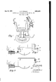
Fig. 1 is a general perspective view of a dental chair and dental engine associated therewith showing a preferred arrangement of my new control device; a
Fig. 2 is a diagrammatic layout of one embodiment of my invention employing an electric circuit as an element of the control means; and. r
T Fig. 3. is another such diagrammatic layout ofa system which is pneumatic throughout.
Referring now more particularly to such drawing, and especially Fig. 1 thereof, the master switch I of the motor controlling circuit for electric motorZ is installed in the base of dental column 3 in the manner explained in my aforesaid co-pending application, master switch I corresponding to switch 16 of such application. Master switch I is a normally open micro-switch'adapted to be operated by move ment of diaphragm 4 in response to pneumatic pressure in chamber 5. Chamber 5 is con nected to a resilient elongated tubular member 6 ordinarily of rubber and sealed at its other end to form a closed system. Such tubular member will preferably be arcuately disposed around the base 1 of the dental chair 8 and may lie beneath the rubber mat 9 ordinarily placed around such base.
Thetool, such as dental drill l0 mounted on theend of jointed boom II is supported when not in use by hook I2 carried by an upper extension of column 3. As explained in my copending application, such hook may be pivotally mounted to operate a switch in an electric circuit. controlling the operation of the motor. The present invention, however, is concerned with means for controlling the pneumatic system itself.
Referring now more particularly to the Fig. 2 embodiment of my invention, a valve [3 is provided in tubular member 6 communicating with the outer atmosphere. An armature I4 is pivoted at [5 to be rocked upon energization of solenoid 16, to close valve l3. When such solenoid is not thus energized, spring I! acts on the armature to force valve I3 open. Valve I3 may, for example, be an ordinary automobile tire valve. The energization of the solenoid is controlled by switch l8 in the upper end of the dental column. Contact member IQ of such switch is forced open by the end of pivoted hook member I 2 when the dental tool is hung upon such hook, as shown in solid lines in Fig. 2. Consequently, in this position solenoid IE will not be energized and valve I3 will be held open so that tubular member 6 is in communication with the outer atmosphere. Foot pressure upon such tubular member, therefore, will be ineffective to operate master switch I when the dental tool is supported upon hook [2. When, however, the operator lifts the tool from such hook, spring 20 is effective to move the hook into dotted line position, as shown in Fig. 2, and spring contact member [9 moves to close switch l8 and activate solenoid "5, thereby closing valve 13. Now that such valve is closed, operation of the dental engine may be initiated and controlled by means of foot pressure on memher 6, as taught in my aforesaid co-pending application. Obviously the air entrapped in the pneumatic system will normally be under the same pressure as the outer atmosphere so that micro-switch I may be set for sensitive response to actuation of diaphragm 4.
Referring now more particularly to Fig. 3 of the drawing, the embodiment of my invention there illustrated is pneumatic throughout without the employment of electrical control means. A small tube 2|, which may be of metal or thick-walled rubber pressure hose is in communication with resilient tubular member 6 and terminates in the upper end of column 3 in a valve 22 which may be of the same type as valve [3, for example. When the dental tool is not hung from hook l2, spring will, of course, be effective to rock such hook out of engagement with valve 22. When, however, the dental tool is placed upon thehook, rotation of the latter will be effective to open valve 22 and place tubular member 6 in communication with the outer atmosphere. It will be seen therefore that foot pressure on member 6 will be ineffective to operate master switch! when the tool is hung from hook l2 and the pneumatic, system will be automatically compensated for variations in atmospheric pressure When, however, the tool is lifted from the hook the pneumatic system is at once closed and responsive to foot pressure on member 6 to move diaphragm 4, to close switch I.
It will be seen from the foregoing that I have provided control means for dental engines and the like employing a pneumatic system in which. ambient temperature and pressure chan es are automatically compensated for, and which is rendered inoperative when the tool connected to such engine has been hung upon its. supporting means.
Other modes of applyin the principle of the invention may be employed, change being made as regards the details described, provided the features stated in any of the following claims, or the equivalent of such, be employed.
I therefore particularly point out and distinctly claim as my invention:
l. A dental engine including an electric motor, a power operated tool adapted to be driven by said engine, a movable support for said tool when not in, use, pneumatic pressure means operative to control operation of said engine, a normally open valve adapted to vent said pneumatic pressure means to render the same inoperative, an electric circuit including a solenoid operative upon energization to close said valve, and a switch in said circuit held open by said movable support only when said tool is resting thereon.
2. A dental engine including an electric motor, a power operated tool adapted to be driven by said engine, a movable support for said tool adapted to be held in one position when said tool is thereon and to move to another position when said tool is removed therefrom, pneumatic pressure means operative to control operation of said engine, said pneumatic pressure means including a normally open valve as a vent therefor, mechanism adapted to operate said valve, and means operative by said support to control said mechanism.
3, A dental engine including an electric motor,
, a power operated tool adapted to be driven by said engine, a movable support for said tool when not in use, pneumatic pressure means operative to control operation of said engine, said pneu-v matic pressure means including a normally open valve as a vent therefor, mechanism adapted ta close said valve including a solenoid, an electric circuit for said solenoid, and a switch in said circuit operative by said movable support.
4. A dental engine, including an electric motor,
, a power operated tool adapted to be driven by said engine, a movable support for said tool, pneumatic pressure means operative to control opera tion of said engine, said pressure pneumatic means including a valve, means in said valve normally holding said valve open to thereby vent said pneumatic pressure means, mechanism 09- erable to overcome the action of said latter means, to close said valve, and means operable by said support to actuate said mechanism.
5. The structure set forth in claim 4 wherein said mechanism embodies a solenoid, an electric circuit therefor, and the support operated means is a switch in said circuit.
HAROLD M.
REFERENCES CITED The following references are of record in the file of this patent:
UNITED STATES PATENTS Number Name Date 1,856,869 Grimme May 3, 1932 2,092,948 Baitinger Sept. 14, 1937 2,098,771 Bogue 1 Nov. 9, 1937 2,318,355 Bailey May 4, 1943 2,403,277 Hall July 2, 1946 2,444,188 Englund June 29, 1948
Priority Applications (2)
| Application Number | Priority Date | Filing Date | Title |
|---|---|---|---|
| US760816A US2561663A (en) | 1947-07-14 | 1947-07-14 | Control means for dental engines and the like |
| US54756A US2561664A (en) | 1947-07-14 | 1948-10-15 | Control means for dental engines and the like |
Applications Claiming Priority (1)
| Application Number | Priority Date | Filing Date | Title |
|---|---|---|---|
| US760816A US2561663A (en) | 1947-07-14 | 1947-07-14 | Control means for dental engines and the like |
Publications (1)
| Publication Number | Publication Date |
|---|---|
| US2561663A true US2561663A (en) | 1951-07-24 |
Family
ID=25060270
Family Applications (1)
| Application Number | Title | Priority Date | Filing Date |
|---|---|---|---|
| US760816A Expired - Lifetime US2561663A (en) | 1947-07-14 | 1947-07-14 | Control means for dental engines and the like |
Country Status (1)
| Country | Link |
|---|---|
| US (1) | US2561663A (en) |
Cited By (6)
| Publication number | Priority date | Publication date | Assignee | Title |
|---|---|---|---|---|
| DE1020768B (en) * | 1955-11-21 | 1957-12-12 | Wolfgang Goedicke | Foot switch arranged in a ring around the base of a medical treatment chair |
| DE1049050B (en) * | 1955-03-31 | 1959-01-22 | Alfred Gebauer | Device for operating dental drills |
| US2929144A (en) * | 1955-01-24 | 1960-03-22 | Raymond L Mellema | Engraver switch |
| US3303303A (en) * | 1964-10-02 | 1967-02-07 | Miller Bros | Pneumatic safety edge for power operated door |
| US4413214A (en) * | 1981-11-12 | 1983-11-01 | The Singer Company | Vented pneumatic foot controller |
| WO1984002263A1 (en) * | 1982-12-11 | 1984-06-21 | Richard Claas Goet | Pneumatically controlled, power-driven tool |
Citations (6)
| Publication number | Priority date | Publication date | Assignee | Title |
|---|---|---|---|---|
| US1856869A (en) * | 1929-09-28 | 1932-05-03 | Grimme Jorge Luis | Electric dental lathe |
| US2092948A (en) * | 1932-04-06 | 1937-09-14 | Ira S Baitinger | Vehicle actuated electric control |
| US2098771A (en) * | 1936-05-08 | 1937-11-09 | Bogue William | Circuit control device |
| US2318355A (en) * | 1941-06-17 | 1943-05-04 | Willard Storage Battery Co | Switch operating means |
| US2403277A (en) * | 1941-11-17 | 1946-07-02 | Glen R Hall | Traffic counter |
| US2444188A (en) * | 1944-11-06 | 1948-06-29 | Edwin H L Englund | Automatic electric toolholding switch |
-
1947
- 1947-07-14 US US760816A patent/US2561663A/en not_active Expired - Lifetime
Patent Citations (6)
| Publication number | Priority date | Publication date | Assignee | Title |
|---|---|---|---|---|
| US1856869A (en) * | 1929-09-28 | 1932-05-03 | Grimme Jorge Luis | Electric dental lathe |
| US2092948A (en) * | 1932-04-06 | 1937-09-14 | Ira S Baitinger | Vehicle actuated electric control |
| US2098771A (en) * | 1936-05-08 | 1937-11-09 | Bogue William | Circuit control device |
| US2318355A (en) * | 1941-06-17 | 1943-05-04 | Willard Storage Battery Co | Switch operating means |
| US2403277A (en) * | 1941-11-17 | 1946-07-02 | Glen R Hall | Traffic counter |
| US2444188A (en) * | 1944-11-06 | 1948-06-29 | Edwin H L Englund | Automatic electric toolholding switch |
Cited By (6)
| Publication number | Priority date | Publication date | Assignee | Title |
|---|---|---|---|---|
| US2929144A (en) * | 1955-01-24 | 1960-03-22 | Raymond L Mellema | Engraver switch |
| DE1049050B (en) * | 1955-03-31 | 1959-01-22 | Alfred Gebauer | Device for operating dental drills |
| DE1020768B (en) * | 1955-11-21 | 1957-12-12 | Wolfgang Goedicke | Foot switch arranged in a ring around the base of a medical treatment chair |
| US3303303A (en) * | 1964-10-02 | 1967-02-07 | Miller Bros | Pneumatic safety edge for power operated door |
| US4413214A (en) * | 1981-11-12 | 1983-11-01 | The Singer Company | Vented pneumatic foot controller |
| WO1984002263A1 (en) * | 1982-12-11 | 1984-06-21 | Richard Claas Goet | Pneumatically controlled, power-driven tool |
Similar Documents
| Publication | Publication Date | Title |
|---|---|---|
| US2561663A (en) | Control means for dental engines and the like | |
| KR880004965A (en) | Tire pressure sensor and air supply to maintain desired tire pressure | |
| US3021719A (en) | Rotor turning gear control apparatus | |
| GB626867A (en) | Improvements in or relating to pneumatic suspension or spring devices | |
| US2561664A (en) | Control means for dental engines and the like | |
| US2574096A (en) | Distributing valve | |
| US2484781A (en) | Windshield wiper motor control | |
| US2182450A (en) | Fluid pressure controlled switch | |
| US2292380A (en) | Timing control | |
| US2172973A (en) | Vacuum cleaner | |
| US3354372A (en) | Delay-responsive shut-off device for operationally-vibrating electric equipment | |
| IE34286L (en) | Speed control of electric motors | |
| US2572272A (en) | Press timer | |
| US4413214A (en) | Vented pneumatic foot controller | |
| US2561668A (en) | Control device for dental engines and the like | |
| US2341587A (en) | Fluid pressure device | |
| US2294339A (en) | Temperature responsive apparatus for rotatable bodies | |
| US2389111A (en) | Control means | |
| US1167132A (en) | Attachment for calculating-machines. | |
| US2648746A (en) | Engine-function switching mechanism | |
| US1453379A (en) | Manual operating means for automatic temperature-control systems | |
| US1599254A (en) | Automatic-stop control for testing machines | |
| US2645125A (en) | Liquid level indicating instrument | |
| US1845278A (en) | Thermostatic switch | |
| US1538824A (en) | Apparatus for automatic speed control of electric motors |