US2555152A - Automatic clutch for power transmission systems - Google Patents
Automatic clutch for power transmission systems Download PDFInfo
- Publication number
- US2555152A US2555152A US26458A US2645848A US2555152A US 2555152 A US2555152 A US 2555152A US 26458 A US26458 A US 26458A US 2645848 A US2645848 A US 2645848A US 2555152 A US2555152 A US 2555152A
- Authority
- US
- United States
- Prior art keywords
- clutch
- speed
- friction clutch
- roller
- positive
- Prior art date
- Legal status (The legal status is an assumption and is not a legal conclusion. Google has not performed a legal analysis and makes no representation as to the accuracy of the status listed.)
- Expired - Lifetime
Links
- 230000005540 biological transmission Effects 0.000 title description 5
- 150000001875 compounds Chemical class 0.000 description 10
- 210000001331 nose Anatomy 0.000 description 4
- 230000004048 modification Effects 0.000 description 2
- 238000012986 modification Methods 0.000 description 2
- 238000013459 approach Methods 0.000 description 1
- 230000000994 depressogenic effect Effects 0.000 description 1
- 238000005096 rolling process Methods 0.000 description 1
Images

Classifications
-
- F—MECHANICAL ENGINEERING; LIGHTING; HEATING; WEAPONS; BLASTING
- F16—ENGINEERING ELEMENTS AND UNITS; GENERAL MEASURES FOR PRODUCING AND MAINTAINING EFFECTIVE FUNCTIONING OF MACHINES OR INSTALLATIONS; THERMAL INSULATION IN GENERAL
- F16D—COUPLINGS FOR TRANSMITTING ROTATION; CLUTCHES; BRAKES
- F16D45/00—Freewheels or freewheel clutches combined with automatic clutches
Definitions
- This invention relates to automatic clutches for power transmission systems.
- the general object of the invention is to provide an automatic compound clutch which will be suitable for connecting a driving motor to a fan load, i. e. a load having substantially zero starting torque, and which,
- a particular object of the invention is to provide a satisfactory automatic clutch for the driving transmission of a helicopter rotor.
- a compound clutch comprises in combination a friction clutch and a positive clutch, both serving to connect a driving with a driven member, the positive clutch being of a one-way type and further being automatically engaged by a speed-responsive device, when the driven member exceeds a critical speed, below which the device prevents engagement of the clutch.
- the friction clutch is automatically controlled by a speed-responsive device which engages it progressively as the speed of the driving member increases above a critical speed, engagement being complete at a speed less than the critical speed which determines the engagement of the positive clutch.
- the positive clutch is preferably of the one-way type and an auxiliary positive oneway clutch is arranged in series with the friction clutch, so that the driven member can overrun the driving member freely.
- the auxiliary positive one-way clutch preferably connects the driven member of the friction clutch with the driven shaft.
- the positive clutches are preferably of the ballor roller ratchet-type, the speed-responsive device controlling the main positive clutch being constituted by centrifugal elements carried on rockers pivoted on the driven member and operative to urge the ballor roller-cage in the roller-engaging direction, the cage bein springloaded in the ballor roller-disengaging direction.
- the ballor roller-cage of the auxiliary clutch may be spring loaded in the ballroller-engaging direction.
- Speed-responsive control of the friction clutch may be obtained by means of centrifugal elements pivoted on the driving member of the friction clutch and operative on the shifting clutch memher to urge it in the engaging direction.
- the critical minimum engaging speed of the friction clutch may be provided for by means of a constant spring loading applied either to the centrifugal elements or to the shifting member of the friction clutch in opposition to the centrifugal loading thereof.
- Direct control of the friction clutch, and/or of the main positive clutch by centrifugal elements may be replaced by indirect control by a centrifugally governed servo-motor o motors.
- the. driven member can overrun freely.
- the driving member will overrun when the critical minimum engaging speed of the friction clutch is reached and the driven member falls below this speed, the main positive clutch having automatically disengaged at a higher critical speed, so that risk of stalling of the motor is avoided.
- the friction clutch transmits the whole torque until the second critical speed is reached at which the main positive clutch engages, after which any torque in excess of the capacity of the friction clutch to transmit without slipping is taken up by the main positive clutch.
- This enables the torque-transmitting capacity of the whole clutch assembly at low-speeds to be limited, since below the critical speed at which the main positive clutch engages the torquetransmitting capacity is limited to that of the friction clutch, which can be much less than the maximum torque to be transmitted especially if the torque/speed characteristic of the load is .controllably variable, so that the torque to be transmitted canbe keptquite low until the post:
- a manually or otherwise separately controlled locking device may be provided which locks the speed responsive control means of the friction clutch in an inoperative condition until released.
- the control of such a device may be interconnected with a brake acting on the driven member so that the centrifugal control is locked inoperative until the brake is released.
- centrifugal clutch engaging elements are locked inoperative by spring-loaded trip levers carried by the driving member and engageable by a displaceable roller mounted in the stationary clutch housing to trip the levers and release the weights.
- Figure 1 is an axial section of the compound clutch
- Figures 2 and 3 are radical sections on the line AA and B--B respectively of Figure 1;
- Figure 4 is a detailed view of va modification in axial section
- FIG 5 is a, detailed View taken in the direction of the arrow in Figure 4 (with the clutch plate 8 removed).
- the driving member 6 carries a fixed friction clutch plate 7 and a sliding friction clutch plate 8 between which is a driven clutch plate 9 mounted .on a sleeve H3 forming the outer race of a roller clutch Whose'inner race II is formed on the driven member 12 and whose rollers l3 are trapped in cage t4 havin slotted lugs l5 (only one shown) engaged by springs I 6 anchored on pins l1 fixed in the driven member i2. These springs urge the cage in the direction of the arrow in Figure 3, .whichindicates the direction of rotation, and therefore tend to press the rollers in the direction for engaging the roller clutch and ensure that it engages promptly when the sleeve H1 is moved in the driving direction.
- the sliding plate 8 is engageableby fly-weights in the form of heavy rollers I8 carried by rockers l9, pivoted on the driving member 6 at 30, which are subject to the action of springs tending to hold the rollers is clear of the plate 8, until the driving member 6 has attained a certain (relatively low) speed, above which the-centrifugal force of the rollers exceeds the spring loading and exerts progressively increasing clutch-engaging pressure on the sliding clutch plate as the speed of the driver increases.
- the driving member 6 incorporates an outer race 2
- Pivotpins 25 fixed in the driven member l2 carry rocking levers 26 (one only shown), of which one end carries a weight 27 and theotherengages a, slotted lug .28 formed on the cage 24.
- the centrifugal force of weights '2] applied through the levers 26 tends to. movexthe cage 24in the-direction of the arrow-in Figure 2,'whichr-is the'direction of rotation, and engage (the iIOHBl clutch 2i 2 2, 2 3
- each of the rockers l3 carrying fiy-weight 18 has a notch 31 engageable by the nose of a trip lever 32, pivoted on a pin 33 mounted in the clutch housing forming part Of the driving member 6, and urged into engagement with the notch 3
- the tail 34 of the trip lever is engageable by a roller 36 mounted on a pin 31 carried by the forkend 38 of .a plunger 39, which slides in a housing 43 secured to a stationary casing 4i enclosing the clutch mechanism.
- Plunger 39 is prevented from turning by a grub-screw 43 which enters a keyway 42 formed in the plunger.
- a spring 44 depresses the plunger 39 and causes the roller 36 to engage the tail 3 of the trip lever 32, and the plunger is withdrawable to a position in which the roller 36 clears the tails 3 1 of the trip levers (as shown in dotted lines in Fig. 5) by a control cable 45.
- the control cable 45 may be connected -to a brake for braking the .driven member,- so that the plunger 33 is withdrawn for locking the hyweights out of action when the brake is applied.
- shaftt is eoupled ato aiheli'coptenengine and shaft I2 the lifting rotor of the helicopter.
- fly-weights I8 engage the friction clutch l, 8, 9, and this drives shaft I2 through one-way clutch rollers I 3 (which are spring-loaded in the engaging sense).
- the driven shaft [2 reaches a critical speed at which the flyweights 2'! engage the main one-way positive clutch rollers 23 which can readily be designed to carry the maximum torque of the drive to the rotor.
- both of the one-way clutches operate to permit free-wheeling of the rotor. If the driving torque again predominates (before stoppage of rotation), the reengagement will occur at the main one-way clutch rollers 23, as a positive drive, if the speed of shaft 12 is above the upper of the two critical speeds; but will occur through the slipping friction clutch and the auxiliary one-way clutch rollers l3, if shaft 12 i rotating, below said critical T speed, provided the drive shaft 6 has not dropped below the minimum criticalspeed (the speed at which fly-weights l8 can overcome the springs 20).
- a com-- pound clutch comprising in combination a friction clutch having means of engagement and a positive clutch, said clutches being operatively arranged in parallel whereby each serves to connect said driving and driven members, the positive clutch being of the one-way type and having a trolled and for that purpose has automatic means of engagement comprising a speed-responsive device which engages it progressively as the speed of the driving member increases above a certain minimum critical speed, whereby the friction clutch engagement is complete at a speed less than the critical speed which determines the engagement of the first-mentioned positive clutch.
- a compound clutch as claimed in claim 4, in which the speed responsive device controlling the friction clutch comprises centrifugal elements pivoted on a part moving with the driving member and operative on a part of the friction clutch member to urge it in the engaging direction, and the locking device comprises trip levers moving with the driving member and spring-loaded to engage the centrifugal elements and lock them in inoperative position, together with a displaceable roller movably mounted in a position to trip the levers and release the centrifugal elements.
Landscapes
- Engineering & Computer Science (AREA)
- General Engineering & Computer Science (AREA)
- Mechanical Engineering (AREA)
- One-Way And Automatic Clutches, And Combinations Of Different Clutches (AREA)
Description
y 1951 c. G. PULLIN EI'A'L 2,555,152
AUTOMATIC CLUTCH FOR POWER TRANSMISSION SYSTEMS Filed May 11, 1948 2 Sheets-Sheet 1 ATT RNEY y 1 v c. s. PULLIN rrm. 2,555,15
. AUTOMATIC CLUTCH FOR owskmsmssmn sysms Filed May 11, 1948 2 Sfits-$heet 2 4 40 Q 5 45 K H Patented May 29, 1951 UNITED STATES PATENT OFFICE AUTOMATIC CLUTCH FOR POWER TRANSMISSIGN SYSTEMS son, Southampton,
Delaware Application May 11, 1948, Serial No. 26,458 In Great Britain May 20, 1947 7 Claims. 1
This invention relates to automatic clutches for power transmission systems.
The general object of the invention is to provide an automatic compound clutch which will be suitable for connecting a driving motor to a fan load, i. e. a load having substantially zero starting torque, and which,
(a) Will not engage below a prescribed speed of the driving shaft,
(1)) Will engage smoothly as the speed of the driver is increased above this prescribed minimum,
Will provide a positive drive when the driven shaft approaches its Working speed,
(11) Can provide for limitation of the torque transmissible at low speeds, and
(e) Will allow free overrun of the driven shaft.
A particular object of the invention is to provide a satisfactory automatic clutch for the driving transmission of a helicopter rotor.
According to this invention, a compound clutch comprises in combination a friction clutch and a positive clutch, both serving to connect a driving with a driven member, the positive clutch being of a one-way type and further being automatically engaged by a speed-responsive device, when the driven member exceeds a critical speed, below which the device prevents engagement of the clutch.
In a preferred form of the invention, the friction clutch is automatically controlled by a speed-responsive device which engages it progressively as the speed of the driving member increases above a critical speed, engagement being complete at a speed less than the critical speed which determines the engagement of the positive clutch.
Further, the positive clutch is preferably of the one-way type and an auxiliary positive oneway clutch is arranged in series with the friction clutch, so that the driven member can overrun the driving member freely.
The auxiliary positive one-way clutch preferably connects the driven member of the friction clutch with the driven shaft.
The positive clutches are preferably of the ballor roller ratchet-type, the speed-responsive device controlling the main positive clutch being constituted by centrifugal elements carried on rockers pivoted on the driven member and operative to urge the ballor roller-cage in the roller-engaging direction, the cage bein springloaded in the ballor roller-disengaging direction. The ballor roller-cage of the auxiliary clutch may be spring loaded in the ballroller-engaging direction.
Speed-responsive control of the friction clutch may be obtained by means of centrifugal elements pivoted on the driving member of the friction clutch and operative on the shifting clutch memher to urge it in the engaging direction.
The critical minimum engaging speed of the friction clutch may be provided for by means of a constant spring loading applied either to the centrifugal elements or to the shifting member of the friction clutch in opposition to the centrifugal loading thereof.
Direct control of the friction clutch, and/or of the main positive clutch by centrifugal elements may be replaced by indirect control by a centrifugally governed servo-motor o motors.
Since both the main and auxiliary positive (roller) clutches operate in the same sense, the. driven member can overrun freely. On reduction of speed, either by reduction of input power: or by braking the driven member, the driving member will overrun when the critical minimum engaging speed of the friction clutch is reached and the driven member falls below this speed, the main positive clutch having automatically disengaged at a higher critical speed, so that risk of stalling of the motor is avoided. On starting up, stalling of the motor is prevented by the inability of the friction clutch to transmit torque until the driving member attain the critical minimum engaging speed; thereafter increase of speed of the driving member, on increasing the power input, is limited by the increase of centrifugal engaging pressure on the friction clutch with speed; and this prevents running-away of the motor, should the throttle or equivalent power control he too coarsely operated.
The friction clutch transmits the whole torque until the second critical speed is reached at which the main positive clutch engages, after which any torque in excess of the capacity of the friction clutch to transmit without slipping is taken up by the main positive clutch. This enables the torque-transmitting capacity of the whole clutch assembly at low-speeds to be limited, since below the critical speed at which the main positive clutch engages the torquetransmitting capacity is limited to that of the friction clutch, which can be much less than the maximum torque to be transmitted especially if the torque/speed characteristic of the load is .controllably variable, so that the torque to be transmitted canbe keptquite low until the post:
3 tive clutch is engaged, thus makin possible considerable saving of weight and size of the friction clutch.
To prevent accidental burning out of the friction clutch by speeding up of the motor when the driven member is braked or otherwise subjected to great resistance, a manually or otherwise separately controlled locking device may be provided which locks the speed responsive control means of the friction clutch in an inoperative condition until released. The control of such a device may be interconnected with a brake acting on the driven member so that the centrifugal control is locked inoperative until the brake is released.
In a preferred form of the locking device, centrifugal clutch engaging elements are locked inoperative by spring-loaded trip levers carried by the driving member and engageable by a displaceable roller mounted in the stationary clutch housing to trip the levers and release the weights.
The nature of the invention will be better understood with the aid of the accompanying drawings showing, by way of example only and in a conventional manner, an embodiment of the improved compound clutch.
In the drawings,
Figure 1 is an axial section of the compound clutch;
Figures 2 and 3 are radical sections on the line AA and B--B respectively of Figure 1;
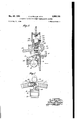
Figure 4 is a detailed view of va modification in axial section;
Figure 5 is a, detailed View taken in the direction of the arrow in Figure 4 (with the clutch plate 8 removed).
In Figures 1 to 3, the driving member 6 carries a fixed friction clutch plate 7 and a sliding friction clutch plate 8 between which is a driven clutch plate 9 mounted .on a sleeve H3 forming the outer race of a roller clutch Whose'inner race II is formed on the driven member 12 and whose rollers l3 are trapped in cage t4 havin slotted lugs l5 (only one shown) engaged by springs I 6 anchored on pins l1 fixed in the driven member i2. These springs urge the cage in the direction of the arrow in Figure 3, .whichindicates the direction of rotation, and therefore tend to press the rollers in the direction for engaging the roller clutch and ensure that it engages promptly when the sleeve H1 is moved in the driving direction.
The sliding plate 8 is engageableby fly-weights in the form of heavy rollers I8 carried by rockers l9, pivoted on the driving member 6 at 30, which are subject to the action of springs tending to hold the rollers is clear of the plate 8, until the driving member 6 has attained a certain (relatively low) speed, above which the-centrifugal force of the rollers exceeds the spring loading and exerts progressively increasing clutch-engaging pressure on the sliding clutch plate as the speed of the driver increases.
The driving member 6 incorporates an outer race 2| of a main roller clutch, whose inner race 22 is formed on the driven' member -12 and whose rollers 23 are trapped in a cage 24. Pivotpins 25 fixed in the driven member l2 carry rocking levers 26 (one only shown), of which one end carries a weight 27 and theotherengages a, slotted lug .28 formed on the cage 24. The centrifugal force of weights '2] applied through the levers 26 tends to. movexthe cage 24in the-direction of the arrow-in Figure 2,'whichr-is the'direction of rotation, and engage (the iIOHBl clutch 2i 2 2, 2 3
but has first to overcome the eifort of springs 29 urging the levers 26 in the opposite direction and tending to move the cage 24 in the direction for preventing the rollers 23 from wedging the races 22$, 22. The strength of springs 29 is so adjusted relatively to the mass of weights 2'! that the roller clutch 2|, 22, 23 cannot engage until the driven member l2 reaches a (relatively high) critical speed which is above that at which the friction clutch becomes fully engaged. Once this criticalspeed is exceeded, the weights 2! overcome the springs 29 and shift the cage 24 in the direction of the arrow and cause the roller clutch 2|, 22-, 23 to engage.
In the modification of Figs. 4 and 5, each of the rockers l3 carrying fiy-weight 18 has a notch 31 engageable by the nose of a trip lever 32, pivoted on a pin 33 mounted in the clutch housing forming part Of the driving member 6, and urged into engagement with the notch 3| by a spring 35 which bears on the tail 34 of the trip lever and finds its abutment on the member 6. The tail 34 of the trip lever is engageable by a roller 36 mounted on a pin 31 carried by the forkend 38 of .a plunger 39, which slides in a housing 43 secured to a stationary casing 4i enclosing the clutch mechanism. Plunger 39 is prevented from turning by a grub-screw 43 which enters a keyway 42 formed in the plunger. A spring 44 depresses the plunger 39 and causes the roller 36 to engage the tail 3 of the trip lever 32, and the plunger is withdrawable to a position in which the roller 36 clears the tails 3 1 of the trip levers (as shown in dotted lines in Fig. 5) by a control cable 45.
When the plunger carrying the roller 36 is withdrawn the trip levers 32 are urged by springs 35 towards the position for engaging the notches 3| of the rockers l9 and, when the member 6 stops rotating and the rockers l9 fall back under the action of springs 23 (see Fig. 1) into the full line position of Fig. 4 the noses of levers 32 enter the notches and lock the fly-weights I8 out of engagement with the clutch plate 8. But .when the tension of the cable 45 is released allowing the spring 44 to depress the plunger 39, the roller 36 strikes the tail 34 of each trip lever in turn as soon as the member 6 is rotated and disengages the noses of the trip levers one after another from the notches 3!, allowing the fly- Weig'hts [8' to move outwards under centrifugal force and engage the clutch plate 8. Once the fly-weights N3 and rockers l'9 have moved outwards to the position shown in chain-dotted lines in Fig. 5 the noses of the trip levers 32 cannot re-engage' the notches f9. The position of the trip levers and fly-weight rockers when the flyweights have moved outwards to their furthest extent, and the friction clutch is fully engaged, is indicatedin-dotted'linesin Fig. 5.
It will be noted that once the fly-weights have been locked out of engagement with the clutch plate 8, they will remain so locked (by engagement'of parts 3|, 32', Fig. 5-), even though the plunger 39 be depressed,- 'until the member 6 is rotated sufiiciently to-br'i'ngthe roller 36 into'con tact successivelywith the several trip eleme'nts 34 all the around the clutch.
The control cable 45 may be connected -to a brake for braking the .driven member,- so that the plunger 33 is withdrawn for locking the hyweights out of action when the brake is applied.
:By way :of summarizing typical operations 0f the :mechanism, it may be assumed that shaftt is eoupled ato aiheli'coptenengine and shaft I2 the lifting rotor of the helicopter. As the engine starts to pick up, it attain a certain minimum critical speed, at which fly-weights I8 engage the friction clutch l, 8, 9, and this drives shaft I2 through one-way clutch rollers I 3 (which are spring-loaded in the engaging sense). After full engagement of the friction clutch, the driven shaft [2 reaches a critical speed at which the flyweights 2'! engage the main one-way positive clutch rollers 23 which can readily be designed to carry the maximum torque of the drive to the rotor. If the rotor shaft l2 should be speeded up by some aerodynamic action of the rotor, or if the engine shaft 6 is slowed down, both of the one-way clutches operate to permit free-wheeling of the rotor. If the driving torque again predominates (before stoppage of rotation), the reengagement will occur at the main one-way clutch rollers 23, as a positive drive, if the speed of shaft 12 is above the upper of the two critical speeds; but will occur through the slipping friction clutch and the auxiliary one-way clutch rollers l3, if shaft 12 i rotating, below said critical T speed, provided the drive shaft 6 has not dropped below the minimum criticalspeed (the speed at which fly-weights l8 can overcome the springs 20). If the whole assembly drops below the minimum critical speed, or if the driven shaft I2 is slowed down below that speed, as by application of the rotor brake, the drive will be disconnected, and not re-connected under those conditions, since the springs 29 of the fly-weights I8 will prevent engagement of the friction clutch, and the springs 29 for the fly-weights 2'! will prevent engagement Of the main positive clutch rollers 23.
We claim:
1. For a power transmission system having a driving member and a driven member, a com-- pound clutch comprising in combination a friction clutch having means of engagement and a positive clutch, said clutches being operatively arranged in parallel whereby each serves to connect said driving and driven members, the positive clutch being of the one-way type and having a trolled and for that purpose has automatic means of engagement comprising a speed-responsive device which engages it progressively as the speed of the driving member increases above a certain minimum critical speed, whereby the friction clutch engagement is complete at a speed less than the critical speed which determines the engagement of the first-mentioned positive clutch.
3. A compound clutch as claimed in claim 2, in which the first-mentioned positive clutch is of the rolling-element type having a rotatable cage for the rolling elements and the speed responsive device controlling it has centrifugal elements carried on rockers pivoted on the driven member and operative to urge the cage in the engaging direction, the cage being spring-loaded in the disengaging direction.
4.-A compound clutch as claimed in claim 2, which includes a separately controlled device for locking the speed-responsive control means of the friction clutch in an inoperative condition.
5. A compound clutch as claimed in claim 4, in which the speed responsive device controlling the friction clutch comprises centrifugal elements pivoted on a part moving with the driving member and operative on a part of the friction clutch member to urge it in the engaging direction, and the locking device comprises trip levers moving with the driving member and spring-loaded to engage the centrifugal elements and lock them in inoperative position, together with a displaceable roller movably mounted in a position to trip the levers and release the centrifugal elements.
6. A compound clutch as claimed in claim 1, in which the auxiliary positive one-way clutch connects the friction clutch with the driven member.
7. A compound clutch as'claimed in claim 1, in which the auxiliary positive clutch is of the rolling-element type having a cage which is springloaded in the engaging direction. I
CYRIL GEORGE PULLIN. KENNETH WATSON.
REFERENCES CITED The following references are of record in the file of this patent:
UNITED STATES PATENTS Number Name Date 551,760 Gere Dec. 24, 1895 1,608,553 Fieux Nov. 30, 1926 1,902,701 Hegemann Mar. 21, 1933 1,935,684 Wemp Nov. 21, 1933
Applications Claiming Priority (1)
| Application Number | Priority Date | Filing Date | Title |
|---|---|---|---|
| GB2555152X | 1947-05-20 |
Publications (1)
| Publication Number | Publication Date |
|---|---|
| US2555152A true US2555152A (en) | 1951-05-29 |
Family
ID=10909996
Family Applications (1)
| Application Number | Title | Priority Date | Filing Date |
|---|---|---|---|
| US26458A Expired - Lifetime US2555152A (en) | 1947-05-20 | 1948-05-11 | Automatic clutch for power transmission systems |
Country Status (1)
| Country | Link |
|---|---|
| US (1) | US2555152A (en) |
Cited By (2)
| Publication number | Priority date | Publication date | Assignee | Title |
|---|---|---|---|---|
| US2910157A (en) * | 1958-04-03 | 1959-10-27 | Bendix Aviat Corp | Two speed gear drive and hub brake for velocipedes and the like |
| US5595273A (en) * | 1995-06-09 | 1997-01-21 | Ford Motor Company | Reverse lock for one-way clutch |
Citations (4)
| Publication number | Priority date | Publication date | Assignee | Title |
|---|---|---|---|---|
| US551760A (en) * | 1895-12-24 | Clutch | ||
| US1608553A (en) * | 1923-11-05 | 1926-11-30 | App Fieux Sa | Torque-limiting device for clutches |
| US1902701A (en) * | 1929-06-24 | 1933-03-21 | Dortmunder Vulkan A G | Ship drive-coupling mechanism |
| US1935684A (en) * | 1931-11-05 | 1933-11-21 | Ernest E Wemp | Clutch |
-
1948
- 1948-05-11 US US26458A patent/US2555152A/en not_active Expired - Lifetime
Patent Citations (4)
| Publication number | Priority date | Publication date | Assignee | Title |
|---|---|---|---|---|
| US551760A (en) * | 1895-12-24 | Clutch | ||
| US1608553A (en) * | 1923-11-05 | 1926-11-30 | App Fieux Sa | Torque-limiting device for clutches |
| US1902701A (en) * | 1929-06-24 | 1933-03-21 | Dortmunder Vulkan A G | Ship drive-coupling mechanism |
| US1935684A (en) * | 1931-11-05 | 1933-11-21 | Ernest E Wemp | Clutch |
Cited By (2)
| Publication number | Priority date | Publication date | Assignee | Title |
|---|---|---|---|---|
| US2910157A (en) * | 1958-04-03 | 1959-10-27 | Bendix Aviat Corp | Two speed gear drive and hub brake for velocipedes and the like |
| US5595273A (en) * | 1995-06-09 | 1997-01-21 | Ford Motor Company | Reverse lock for one-way clutch |
Similar Documents
| Publication | Publication Date | Title |
|---|---|---|
| US3215234A (en) | Automatic clutch | |
| US3197001A (en) | Rotary synchronous clutches | |
| US2120896A (en) | Automatic power transmission for automotive vehicles | |
| US2055300A (en) | Clutch | |
| US2084219A (en) | Power transmission mechanism | |
| US2555152A (en) | Automatic clutch for power transmission systems | |
| US3191732A (en) | Torque responsive clutch with limited torque in one direction and unlimited torque in the opposite direction | |
| US2355710A (en) | Clutch | |
| US2107089A (en) | Transmission mechanism | |
| US2048435A (en) | Centrifugal clutch | |
| US1882805A (en) | Transmission system | |
| US2071588A (en) | Automatic clutch | |
| US2281118A (en) | Rotor brake | |
| US1926783A (en) | Automatic clutch lock-out device | |
| US2673633A (en) | Torque and speed responsive clutch | |
| US3369638A (en) | Clutch mechanism for dual-input, single-output control system | |
| US3677378A (en) | Self-energizing torque limiting disc clutch | |
| US2055177A (en) | Automatic clutch | |
| US2072117A (en) | Clutch mechanism | |
| US2232454A (en) | Automatic power transmitting mechanism | |
| US2018101A (en) | Automatic clutch | |
| US1793735A (en) | Automatic accelerating friction clutch | |
| US2216771A (en) | Automatic clutch | |
| US3129794A (en) | Clutch construction | |
| US1910141A (en) | Clutch |