US2552182A - Differential actuator - Google Patents
Differential actuator Download PDFInfo
- Publication number
- US2552182A US2552182A US126906A US12690649A US2552182A US 2552182 A US2552182 A US 2552182A US 126906 A US126906 A US 126906A US 12690649 A US12690649 A US 12690649A US 2552182 A US2552182 A US 2552182A
- Authority
- US
- United States
- Prior art keywords
- sun gear
- shaft
- gear
- actuator
- drive
- Prior art date
- Legal status (The legal status is an assumption and is not a legal conclusion. Google has not performed a legal analysis and makes no representation as to the accuracy of the status listed.)
- Expired - Lifetime
Links
Images

Classifications
-
- G—PHYSICS
- G06—COMPUTING OR CALCULATING; COUNTING
- G06C—DIGITAL COMPUTERS IN WHICH ALL THE COMPUTATION IS EFFECTED MECHANICALLY
- G06C23/00—Driving mechanisms for functional elements
- G06C23/04—Driving mechanisms for functional elements of pin carriage, e.g. for step-by-step movement
Definitions
- This invention relates to a numeral wheel register actuating d-evice.
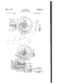
- Fig, l is a part elevation and part sectional view, taken substantially along the line I-i of Fig. 2, showing the differential control mechanism, and further includes a numeral wheel register unit and a value selecting element, all in operative relation;
- Fig. 2 is a part sectional and part elevational view taken along the line 2--2 of Fig, l;
- Fig. 3 is a detail view showing a manual form of cyclical drive means
- Fig. 4 is a part elevational and part sectional view taken along the line 4-4 of Fig. 2, and showing a cam arrangement for the control of the setting of radially adjustable actuator teeth;
- Fig. 5 is a detail view of the actuator shown in Fig. 4i, and part of the cam structure removed to show the arrangement of the structural teeth;
- Fig. 6 is an enlarged sectional view through a portion of the differential structure, and further includes a portion of the tooth supporting and adjusting structure, with a tooth shown in an actuating position;
- Fig. 7 is a plan View of the numeral register wheels taken in the direction of the arrow 1, Fig. 2.
- a registering or accumulating unit is supported between walls II--I Ia, as best shown in Fig. 2.
- Said accumulating mechanism generally comprises numeral wheels I2, mounted on a shaft I3.
- Each numeral wheel I2 is preferably of known differential drive construction, such as the type illustrated in Patent 1,281,163, and each wheel has a drive gear I4 associated therewith which eifects the drive of the diierential ther-ein.
- FIG. 1 In the structure shown in Fig. 1, two sets of numeral wheels iZ-IQ are shown, one set being adapted to register in an ascending order and the other in a descending order. Between pairs of numeral wheels of each order, an intermediate drive is provided, as indicated by the gear I5 2 meshing with the gears Ill-Id in Fig, l. Said gears I5 are carried by a shaft IB. A Geneva transfer pinion, indicated at il, is also provided between each set of numeral wheels to effect tens transfer from the numeral wheel of lower order to the numeral wheel of higher order, as best shown in Fig. 7.
- each numeral wheel intermediate drive gear I5 is a differentially controlled actuator, generally indicated at A, Fig. 1, which actuator is adapted to control the drive of a further intermediate gear I8, meshing with the intermediate drive gear I5.
- the gears I8 are mounted on a shaft I9.
- Each actuator unit A also has a value setting number 2i associated therewith which is arranged to adjust a desired number of teeth vto an actuating position relative to teethof a pinion 20, which pinion is Xed to the gear i8.
- the actuator includes planetary differential mechanism comprising an internal ring gear 22, rotatively mounted within a shell 23, and is supported in the side wall II or Ha.
- a planetary pinion 24 is mounted on a pin 25, said pin being supported by the shell 23, and meshes with the teeth of the internal ring gear 22.
- a sun gear 26 which gear rotates freely around an extended hub portion 27a of a sun gear member 2l associated with the actuator of next higher order.
- the sun gear 2 is fixed to a cyclically driven shaft 28.
- Another sun gear 29 is also xed to said cyclically driven shaft 23, and is adapted to mesh with a second planetary pinion tI, which pinion is carried by a pin Si? ixed to the wall II or Ila.
- Said second planetary pinion 3l also meshes with the teeth of the internal ring gear 22.
- the sun gear 26, planetary gear 24, and ring gear 22 will form one portion of the differential structure, which, as will be later described, is associated with Value setting operations, and that the sun gear 29, planetary pinion 3l, along with the ring gear 22 are associated with the driving cycle of differential operation, when the shaft 28 is rotated.
- each toothed element comprises a disc 33, xed to the portion 2lb, Fig. 6, of the sun gear 21, and is provided with radially positioned slots 35.
- a slidable two-toothed element 36 Within each slot 5 is mounted a slidable two-toothed element 36, having a shank portion 36a engaging the slot.
- Each toothed element further has a pin 3l' extending from one face thereof, which pins are adapted to engage a cam slot 4I in a cam disc 39.
- Said cam disc 39 is shown as an integral part of the hub portion of the sun gear 26 and therefor moves with the said sun gear.
- the shell 23 has an external toothed segment portion 42, Fig. 1, which is adapted to be engaged by a toothed segment i3 formed on a setting lever 2
- Said setting lever 2l is pivotally mounted upon a shaft 45, and when rocked about said shaft is adapted to rock the shell 23.
- Rocking of the shell 23 effects rotation of the planetary pinion 24, as it moves around the teeth of the internal ring gear 22, inasmuch as the ring gear is retained in a fixed position by the planetary pinion 3
- Rotation of the planetary pinion 24 causes the sun gear 26 to rotate, Ywhich in turn rotates the cam disc 39 to effect the projection of the desired number of toothed elements 96 to an actuating position.
- the shaft 28 is adapted to be rotated through one complete revolution by a crank 49, whereupon the projected teeth of the toothed elements 36 will engage the teeth of the pinion 29 and drive the intermediate gear I8 to thus effect the drive of the register numeral wheels i2.
- the rotation of the splined shaft 28 effects rotation of the sun gear 29, which gear drives the planetary pinion 3l around its xed pivot pin 39, to thus rotate the ring gear 22 and sun gear 29.
- the ratio between the sun gear 29 and pinion 3i is 2 to l.
- the ratio between planetary pinion 29 and sun gear 26 is 1 to 2.
- the pinions 3i and 29 will be driven at twice the speed of the sun gear 29, and the sun gear 26 will move at the same relative speed and in the same direction as the sun gear 29. Therefore, the cam disc 99 will move about the hub 27a at the same speed as the actuator disc 33 which is fixed to the hub 21h.
- Stop means is generally indicated at 41, Fig. 3, to limit each cycle of operation to 360.
- Said stop means may be of any desired construction, but, for the purpose of illustration, comprises a horizontally slidable pin 48, normally urged to a stop position relative to the operating crank 49 by means of a spring I.
- a register actuating device a cyclically driven shaft, a bracket to support said shaft, a numeral wheel accumulator including a geared drive therefor, a rotatable actuator unit having settable teeth operatively associated with the geared drive and driven by said shaft, a differential unit supported on said shaft adjacent the i actuator unit and including a shell having an internal gear freely supported therein, a planetary pinion supported by the shell and meshing with the internal gear, a planetary pinion carried by the shaft supporting bracket and meshing with the internal gear, an actuator tooth setting sun gear meshing with the first named planetary pinion and freely rotatable about the shaft axis, a cam associated with said settable teeth and connected with the sun gear, manually controlled means to effect adjustment of said shell, whereby the sun gear and cam may be rotated and a desired number of teeth may be placed in an accumulator actuator position, and a second sun gear fixed to the shaft and meshing with the second named planetary pinion, whereby, during a cycle of operation of said shaft the
- a register actuating device a cyclically driven shaft, a bracket to support said shaft, a numeral wheel accumulator including a geared drive therefor, a rotatable actuator unit having settable teeth operatively associated with the geared drive and driven by said shaft, a differential unit supported on said shaft adjacent the actuator unit and including a shell having an internal gear freely supported therein, said shell having a toothed peripheral portion, a planetary Ypinion supported by the shell and meshing with the internal gear, a planetary pinion carried by the shaft supporting bracket and meshing with the internal gear, an actuator tooth setting sun gear meshing with the first named planetary pinion and freely rotatable about the shaft axis, a cam associated with said settable teeth and connected with the sun gear, a toothed setting lever meshing with the toothed portion of the shell to effect adjustment of said shell, whereby the sun gear and cam may be rotated and a desired number of teeth may be placed in an accumulator actuating position, and a second sun gear fixed to
Landscapes
- Engineering & Computer Science (AREA)
- Physics & Mathematics (AREA)
- Computer Hardware Design (AREA)
- Computing Systems (AREA)
- General Physics & Mathematics (AREA)
- Theoretical Computer Science (AREA)
- Retarders (AREA)
Description
May 8, 1951 B. KNAUER 2,552,182
DIFFERENTIAL ACTUATOR Filed Nov. 12, 1949 2 Sheets-Sheet l ATTORNEY May 8, 1951 B. KNAUER DIFFERENTIAL ACTUATOR 2 Sheets-Sheet 2 Filed Nov. l2, 1949 INVEN R 667" /76 06f' ATTORNEY Patented May vi951 UNITED STATES PATENT OFFICE DIFFERENTIAL ACTUATOR Application November 12, 1949, Serial No. 126,906
2 Claims.
This invention relates to a numeral wheel register actuating d-evice.
It is the principal object of the present invention to combine differential mechanism with both value setting and cyclical drive portions of register actuating mechanism arranged on a cyclically driven shaft, in a manner which will permit the value setting elements to remain in constant operative setting relation with the actuator during an accumulating cycle of operation.
By way of example, one preferred embodiment cf the invention is illustrated in the drawings, wherein:
Fig, l is a part elevation and part sectional view, taken substantially along the line I-i of Fig. 2, showing the differential control mechanism, and further includes a numeral wheel register unit and a value selecting element, all in operative relation;
Fig. 2 is a part sectional and part elevational view taken along the line 2--2 of Fig, l;
Fig. 3 is a detail view showing a manual form of cyclical drive means;
Fig. 4 is a part elevational and part sectional view taken along the line 4-4 of Fig. 2, and showing a cam arrangement for the control of the setting of radially adjustable actuator teeth;
Fig. 5 is a detail view of the actuator shown in Fig. 4i, and part of the cam structure removed to show the arrangement of the structural teeth;
Fig. 6 is an enlarged sectional view through a portion of the differential structure, and further includes a portion of the tooth supporting and adjusting structure, with a tooth shown in an actuating position; and
Fig. 7 is a plan View of the numeral register wheels taken in the direction of the arrow 1, Fig. 2.
Referring to the drawings in detail, a registering or accumulating unit, indicated generally at lil, is supported between walls II--I Ia, as best shown in Fig. 2. Said accumulating mechanism generally comprises numeral wheels I2, mounted on a shaft I3. Each numeral wheel I2 is preferably of known differential drive construction, such as the type illustrated in Patent 1,281,163, and each wheel has a drive gear I4 associated therewith which eifects the drive of the diierential ther-ein.
In the structure shown in Fig. 1, two sets of numeral wheels iZ-IQ are shown, one set being adapted to register in an ascending order and the other in a descending order. Between pairs of numeral wheels of each order, an intermediate drive is provided, as indicated by the gear I5 2 meshing with the gears Ill-Id in Fig, l. Said gears I5 are carried by a shaft IB. A Geneva transfer pinion, indicated at il, is also provided between each set of numeral wheels to effect tens transfer from the numeral wheel of lower order to the numeral wheel of higher order, as best shown in Fig. 7.
Associated with each numeral wheel intermediate drive gear I5 is a differentially controlled actuator, generally indicated at A, Fig. 1, which actuator is adapted to control the drive of a further intermediate gear I8, meshing with the intermediate drive gear I5. The gears I8 are mounted on a shaft I9.
Each actuator unit A also has a value setting number 2i associated therewith which is arranged to adjust a desired number of teeth vto an actuating position relative to teethof a pinion 20, which pinion is Xed to the gear i8.
The actuator includes planetary differential mechanism comprising an internal ring gear 22, rotatively mounted within a shell 23, and is supported in the side wall II or Ha. A planetary pinion 24 is mounted on a pin 25, said pin being supported by the shell 23, and meshes with the teeth of the internal ring gear 22. Also meshing with said planetary pinion 24 is a sun gear 26, which gear rotates freely around an extended hub portion 27a of a sun gear member 2l associated with the actuator of next higher order. The sun gear 2 is fixed to a cyclically driven shaft 28. Another sun gear 29 is also xed to said cyclically driven shaft 23, and is adapted to mesh with a second planetary pinion tI, which pinion is carried by a pin Si? ixed to the wall II or Ila. Said second planetary pinion 3l also meshes with the teeth of the internal ring gear 22.
From the description of the differential structure so far, it will be seen that the sun gear 26, planetary gear 24, and ring gear 22 will form one portion of the differential structure, which, as will be later described, is associated with Value setting operations, and that the sun gear 29, planetary pinion 3l, along with the ring gear 22 are associated with the driving cycle of differential operation, when the shaft 28 is rotated.
Referring now to the construction and operation of the toothed portion of the actuator, the same comprises a disc 33, xed to the portion 2lb, Fig. 6, of the sun gear 21, and is provided with radially positioned slots 35. Within each slot 5 is mounted a slidable two-toothed element 36, having a shank portion 36a engaging the slot. Each toothed element further has a pin 3l' extending from one face thereof, which pins are adapted to engage a cam slot 4I in a cam disc 39. Said cam disc 39 is shown as an integral part of the hub portion of the sun gear 26 and therefor moves with the said sun gear.
The shell 23 has an external toothed segment portion 42, Fig. 1, which is adapted to be engaged by a toothed segment i3 formed on a setting lever 2|. Said setting lever 2l is pivotally mounted upon a shaft 45, and when rocked about said shaft is adapted to rock the shell 23. Rocking of the shell 23 effects rotation of the planetary pinion 24, as it moves around the teeth of the internal ring gear 22, inasmuch as the ring gear is retained in a fixed position by the planetary pinion 3| during a value setting period. Rotation of the planetary pinion 24 causes the sun gear 26 to rotate, Ywhich in turn rotates the cam disc 39 to effect the projection of the desired number of toothed elements 96 to an actuating position.
After the setting of the toothed elements, the shaft 28 is adapted to be rotated through one complete revolution by a crank 49, whereupon the projected teeth of the toothed elements 36 will engage the teeth of the pinion 29 and drive the intermediate gear I8 to thus effect the drive of the register numeral wheels i2.
During the cycle of operation, the rotation of the splined shaft 28 effects rotation of the sun gear 29, which gear drives the planetary pinion 3l around its xed pivot pin 39, to thus rotate the ring gear 22 and sun gear 29. The ratio between the sun gear 29 and pinion 3i is 2 to l. The ratio between planetary pinion 29 and sun gear 26 is 1 to 2. Hence, the pinions 3i and 29 will be driven at twice the speed of the sun gear 29, and the sun gear 26 will move at the same relative speed and in the same direction as the sun gear 29. Therefore, the cam disc 99 will move about the hub 27a at the same speed as the actuator disc 33 which is fixed to the hub 21h.
Stop means is generally indicated at 41, Fig. 3, to limit each cycle of operation to 360. Said stop means may be of any desired construction, but, for the purpose of illustration, comprises a horizontally slidable pin 48, normally urged to a stop position relative to the operating crank 49 by means of a spring I.
Having described the invention what is claimed is:
1. In a register actuating device, a cyclically driven shaft, a bracket to support said shaft, a numeral wheel accumulator including a geared drive therefor, a rotatable actuator unit having settable teeth operatively associated with the geared drive and driven by said shaft, a differential unit supported on said shaft adjacent the i actuator unit and including a shell having an internal gear freely supported therein, a planetary pinion supported by the shell and meshing with the internal gear, a planetary pinion carried by the shaft supporting bracket and meshing with the internal gear, an actuator tooth setting sun gear meshing with the first named planetary pinion and freely rotatable about the shaft axis, a cam associated with said settable teeth and connected with the sun gear, manually controlled means to effect adjustment of said shell, whereby the sun gear and cam may be rotated and a desired number of teeth may be placed in an accumulator actuator position, and a second sun gear fixed to the shaft and meshing with the second named planetary pinion, whereby, during a cycle of operation of said shaft the differential geared unit will effect control of the drive of the first named sun gear to provide the same relative speed of rotation as that of the cyclical drive.
2. In a register actuating device, a cyclically driven shaft, a bracket to support said shaft, a numeral wheel accumulator including a geared drive therefor, a rotatable actuator unit having settable teeth operatively associated with the geared drive and driven by said shaft, a differential unit supported on said shaft adjacent the actuator unit and including a shell having an internal gear freely supported therein, said shell having a toothed peripheral portion, a planetary Ypinion supported by the shell and meshing with the internal gear, a planetary pinion carried by the shaft supporting bracket and meshing with the internal gear, an actuator tooth setting sun gear meshing with the first named planetary pinion and freely rotatable about the shaft axis, a cam associated with said settable teeth and connected with the sun gear, a toothed setting lever meshing with the toothed portion of the shell to effect adjustment of said shell, whereby the sun gear and cam may be rotated and a desired number of teeth may be placed in an accumulator actuating position, and a second sun gear fixed to the shaft and meshing with the second named planetary pinion, whereby, during a cycle of operation of said shaft the differential geared unit will effect control of the drive of the first named sun gear to provide the same relative speed of rotation as that of the cyclical drive.
BERTHOLD KNAUER.
REFERENCES CITED The following references are of record in the file of this patent:
UNITED STATES PATENTS Number Name Date 2,482,935 Rast Sept. 27, 1949
Priority Applications (1)
| Application Number | Priority Date | Filing Date | Title |
|---|---|---|---|
| US126906A US2552182A (en) | 1949-11-12 | 1949-11-12 | Differential actuator |
Applications Claiming Priority (1)
| Application Number | Priority Date | Filing Date | Title |
|---|---|---|---|
| US126906A US2552182A (en) | 1949-11-12 | 1949-11-12 | Differential actuator |
Publications (1)
| Publication Number | Publication Date |
|---|---|
| US2552182A true US2552182A (en) | 1951-05-08 |
Family
ID=22427317
Family Applications (1)
| Application Number | Title | Priority Date | Filing Date |
|---|---|---|---|
| US126906A Expired - Lifetime US2552182A (en) | 1949-11-12 | 1949-11-12 | Differential actuator |
Country Status (1)
| Country | Link |
|---|---|
| US (1) | US2552182A (en) |
Citations (1)
| Publication number | Priority date | Publication date | Assignee | Title |
|---|---|---|---|---|
| US2482935A (en) * | 1949-09-27 | Value printing and registering |
-
1949
- 1949-11-12 US US126906A patent/US2552182A/en not_active Expired - Lifetime
Patent Citations (1)
| Publication number | Priority date | Publication date | Assignee | Title |
|---|---|---|---|---|
| US2482935A (en) * | 1949-09-27 | Value printing and registering |
Similar Documents
| Publication | Publication Date | Title |
|---|---|---|
| US2510350A (en) | Postage printing and metering device | |
| US2552182A (en) | Differential actuator | |
| US2248195A (en) | Clock | |
| US2248257A (en) | Register actuating device | |
| US2636339A (en) | Cyclometer indicator mechanism for twenty-four hour cyclometer clocks | |
| US3645087A (en) | Digital clock with additional data indication | |
| US3090249A (en) | Interval timer | |
| US2306499A (en) | Register actuator | |
| US2565024A (en) | Cooking timing machine | |
| US1685481A (en) | Counting mechanism | |
| US2700903A (en) | Adjustable gearing | |
| US2316626A (en) | Control device | |
| US2437401A (en) | Time controlling mechanism | |
| US3279166A (en) | Timepiece of the numeral indicating type | |
| US2530996A (en) | Differential actuating mechanism | |
| US2561790A (en) | Date indicator | |
| US2167505A (en) | Translating mechanism | |
| US2701439A (en) | Clock alarm device settable to the minute | |
| US2176870A (en) | Clock | |
| US3168981A (en) | Printing mechanism for fluid meters | |
| US2499121A (en) | Coin controlled device | |
| US2670592A (en) | Timepiece winding indicator | |
| US2645426A (en) | Predetermined counter value setting device | |
| US2176205A (en) | Caixjclating machine | |
| US2269290A (en) | Speed-change mechanism |