US2548843A - Fire escape ladder - Google Patents
Fire escape ladder Download PDFInfo
- Publication number
- US2548843A US2548843A US671931A US67193146A US2548843A US 2548843 A US2548843 A US 2548843A US 671931 A US671931 A US 671931A US 67193146 A US67193146 A US 67193146A US 2548843 A US2548843 A US 2548843A
- Authority
- US
- United States
- Prior art keywords
- connector
- spacer
- spacers
- rungs
- fire escape
- Prior art date
- Legal status (The legal status is an assumption and is not a legal conclusion. Google has not performed a legal analysis and makes no representation as to the accuracy of the status listed.)
- Expired - Lifetime
Links
Images
Classifications
-
- E—FIXED CONSTRUCTIONS
- E06—DOORS, WINDOWS, SHUTTERS, OR ROLLER BLINDS IN GENERAL; LADDERS
- E06C—LADDERS
- E06C1/00—Ladders in general
- E06C1/52—Ladders in general with non-rigid longitudinal members
- E06C1/56—Rope or chain ladders
Definitions
- My invention relates to fire escape ladders and especially such ladders as will provide the minimum danger of accident or loss of life in the use thereof, it being understood that the ladder must furnish means of descending from a point some distance from theground to the ground or a similar point ofsafety and it is tobe remembered that persons using such means of escape from a fire or similar emergency are necessarily under considerable excitement or strain.
- One of the main objects of the invention is to insure that the user of the ladder will have the most desirable foot and hand hold in all situations thatare commonly met with. To that end the design presents sufficient clearance between a vertical wall and the rungs to give the proper foot hold on the rungs and likewise furnishes the proper hold, if there is an obstructing fiat or inclined surface.
- Another object is to make the construction of parts suitable for storing in a room or similar place, and yet sufiiciently and inexpensive to meet the requirements of the user. It must also be capable of being suspended from one fixed point with the maximum of speed and minimum of danger of disarrangement.
- Figure 1 is an elevation of the fire escape ladder supported from a window
- Figure 2 is a detail view of a spacer showing an end of a connector in dotted lines
- Figure 3 is a detail showing a rung broken away, the rung, connector and spacer being assembled together
- Figure 4 is a detail view showing a link having its body portion retain the socket of a connector of metal.
- FIG. 1 there is shown said ladder, extending from a window.
- the chains for supporting the rungs are marked I, the rungs being indicated by 2 and the ladder is shown extending downwardly adjacent to a vertical wall and its lower part contacting an obstructing sloping fiat surface such as a roof.
- the connector is indicated by 3.
- the connector 3 is shown having one end formed with a socket B for a link of chain I and a lug I which projects through an opening in the spacer 4 and the spacer is rigidly secured to said connector by rivets thereby clamping the body portions of the link to the connector.
- the square shaped lug (Figs. 3 and 4) projecting from the connector atr spacer 4 is anchored against turning and twisting at that point and is secured at two other points to the-connector, the central point of application being intermediate the two arms of the link and in line with the axis of the connector,
- Figure 4 discloses'clearly the body position of a link secured to said connector with its free ends projecting beyond-said connector and having adjacent. links pliably secured thereto.
- the spacers are preferably shaped and mounted in a way to give them a dual function i. e. that of spacing the rungs from any vertical walls and also spacing them above the roof or fiat sloping surface of any obstructing building or structure to enable persons to secure the proper hold by foot or hand.
- the spacers are somewhat elongated and ovate shaped and by that is meant that they project some distance and increase in width or breadth from the point of attachment.
- the dimensions of said spacer are preferably about inch wide at point of attachment and 2%" at widest part of the opposite end and 4 in length.
- the outer periphery of the spacer is rolled as shown in Figure 3.
- a fire escape ladder comprising flexible metal chains having elongated links, metal rungs and fiat, substantially ovate spacers having reduced ends, a single detachable connector having a body portion with a cylindricalbeariiig for the rung projecting from said body portion, seats formed integrally with said body portion for enclosing the shanks of a link, theends of the links being flexibly secured toother links, a solidliig of said attachment beyond the ends of the rungs for enclosing and anchoring the links within same, a square-shaped lug integral with said attachment capable of fitting within a square'hole in said spacer near its reduced end for anchoring the spacer to said attachment, wings or arms integrally formed as part of said attachment forming bearing surfaces for said spacer,- the projecting wings assisting in resisting any sudden movements of the rung
- a fire escape ladder comprising flexible metal chains having elongated links, metal rungs and fiat, substantially ovate spacers having reduced ends, a single detachable connector having'a body portion with a cylindrical bearing projecting from said body portion for fastening a rung to said connectorfseats formed integrally with said body portion for enclosing and rigidly securing the shanks of alink, a solid squareshaped lug projecting outwardly of said connector for anchoringthereduced ends of said spacer to "said attachment transversely to said rungs, and wings orarm's projectingfromsaid body portion furnishing bearingsurfaces for said spacers and supporting fastening means for securing said connector andspacer, the projecting wings assisting in giving stability to thespace'rs.
- a fire escapeladder comprising metal chains with elongated links, rungs and substantially fiat and ovate metal spacers in combination with a unitary, one pieceattachme'nt -or connector for distributing the strains caused by forces exerted on'the rungs, the rungs: being rigidly securedto said attachment, seats formed in the'body portion Giant area to prevent undesired rocking of said spacers.
Landscapes
- Ladders (AREA)
Description
w. R. MOELLER FIRE ESCAPE LADDER April 1-0, '1951 Filed May 2 4 J, 1946 FIG. I
INVENTOR ATTORNEY l atented Apr. i, 195i FIRE ESCAPE LADDER William R. Moellcr, College Point, N. Y., assignor to Superior Fire Equipment Corporation,
New York, N. Y.
' Application May 24, 1946, Serial No. 671,931
'4 Claims.
My invention relates to fire escape ladders and especially such ladders as will provide the minimum danger of accident or loss of life in the use thereof, it being understood that the ladder must furnish means of descending from a point some distance from theground to the ground or a similar point ofsafety and it is tobe remembered that persons using such means of escape from a fire or similar emergency are necessarily under considerable excitement or strain.
One of the main objects of the invention is to insure that the user of the ladder will have the most desirable foot and hand hold in all situations thatare commonly met with. To that end the design presents sufficient clearance between a vertical wall and the rungs to give the proper foot hold on the rungs and likewise furnishes the proper hold, if there is an obstructing fiat or inclined surface.
Another object is to make the construction of parts suitable for storing in a room or similar place, and yet sufiiciently and inexpensive to meet the requirements of the user. It must also be capable of being suspended from one fixed point with the maximum of speed and minimum of danger of disarrangement.
Qther objects and advantages will be in part indicated in the following description and in part rendered apparent therefrom in connection with the annexed drawing. a
To enable others skilled in the art so fully to apprehend the underlying features hereof that they may embody the sam in the various ways contemplated by this invention, drawings depicting a preferred typical construction have been annexed as a part of this disclosure and, in such drawings, like characters of reference denote corresponding parts throughout all the views, of which:
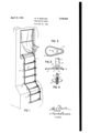
Figure 1 is an elevation of the fire escape ladder supported from a window; Figure 2 is a detail view of a spacer showing an end of a connector in dotted lines; Figure 3 is a detail showing a rung broken away, the rung, connector and spacer being assembled together; Figure 4 is a detail view showing a link having its body portion retain the socket of a connector of metal.
Referring to Figure 1 there is shown said ladder, extending from a window. The chains for supporting the rungs are marked I, the rungs being indicated by 2 and the ladder is shown extending downwardly adjacent to a vertical wall and its lower part contacting an obstructing sloping fiat surface such as a roof.
In Figures 1, 2 and 3 the spacers are marked 4.
In Figure 3 and in dotted line in Figure 2 the connector is indicated by 3. In Figure 3 the connector 3 is shown having one end formed with a socket B for a link of chain I and a lug I which projects through an opening in the spacer 4 and the spacer is rigidly secured to said connector by rivets thereby clamping the body portions of the link to the connector. The square shaped lug (Figs. 3 and 4) projecting from the connector atr spacer 4 is anchored against turning and twisting at that point and is secured at two other points to the-connector, the central point of application being intermediate the two arms of the link and in line with the axis of the connector,
" thereby insuring that no rocking, of the spacer can occur.- The other end of said connector is formed with a tubular bearing 8 and the rung 2 is shown rigidly secured on said tubular bearing.
Figure 4 discloses'clearly the body position of a link secured to said connector with its free ends projecting beyond-said connector and having adjacent. links pliably secured thereto.
.The spacers are preferably shaped and mounted in a way to give them a dual function i. e. that of spacing the rungs from any vertical walls and also spacing them above the roof or fiat sloping surface of any obstructing building or structure to enable persons to secure the proper hold by foot or hand. To that end the spacers are somewhat elongated and ovate shaped and by that is meant that they project some distance and increase in width or breadth from the point of attachment. Having the body portion of the link clamped to a connector with the free ends of the link projecting beyond the connector, insures that there will be flexibility of the chain at that point which together with the proper shaping of the spacer insures that the rung will be slightly raised from any obstructing horizontal or fiat surface. For that purpose the dimensions of said spacer are preferably about inch wide at point of attachment and 2%" at widest part of the opposite end and 4 in length. The outer periphery of the spacer is rolled as shown in Figure 3.
Without further analysis, the foregoing will so fully reveal the gist of this invention that others can, by applying current knowledge, readily adapt it for various utilizations by retaining one 1. In a fire escape ladder comprising flexible metal chains having elongated links, metal rungs and fiat, substantially ovate spacers having reduced ends, a single detachable connector having a body portion with a cylindricalbeariiig for the rung projecting from said body portion, seats formed integrally with said body portion for enclosing the shanks of a link, theends of the links being flexibly secured toother links, a solidliig of said attachment beyond the ends of the rungs for enclosing and anchoring the links within same, a square-shaped lug integral with said attachment capable of fitting within a square'hole in said spacer near its reduced end for anchoring the spacer to said attachment, wings or arms integrally formed as part of said attachment forming bearing surfaces for said spacer,- the projecting wings assisting in resisting any sudden movements of the rung or link, thereby distributing the strains exerted upon said spacer over a sulfiprojecting outwardly from said connector rer' anchoring a spacer at its reduced end transversely to said rung and'win'g's or armsfurnis'hing'bearing "surfaces for a spacer projecting from "said connector and capableof supporting fastening means for securing the connector to the spacers whereby the spacers are heldagainst undesirable rocking.
2. In a fire escape ladder comprising flexible metal chains having elongated links, metal rungs and fiat, substantially ovate spacers having reduced ends, a single detachable connector having'a body portion with a cylindrical bearing projecting from said body portion for fastening a rung to said connectorfseats formed integrally with said body portion for enclosing and rigidly securing the shanks of alink, a solid squareshaped lug projecting outwardly of said connector for anchoringthereduced ends of said spacer to "said attachment transversely to said rungs, and wings orarm's projectingfromsaid body portion furnishing bearingsurfaces for said spacers and supporting fastening means for securing said connector andspacer, the projecting wings assisting in giving stability to thespace'rs. V
3. A fire escapeladder comprising metal chains with elongated links, rungs and substantially fiat and ovate metal spacers in combination with a unitary, one pieceattachme'nt -or connector for distributing the strains caused by forces exerted on'the rungs, the rungs: being rigidly securedto said attachment, seats formed in the'body portion Giant area to prevent undesired rocking of said spacers. a
4. In'fa fire efsca'p'ieladder comprising a pair of flexible metal chains with elongated links, metal rungs, and substantially oval-shaped spacers having the figure of the longitudinal section of an 'egg eccentrically mounted on said chains in combination with a one piece attachment or connection having a plurality of bearing 'surfa'cesfor said links, rungs and spacers, including seats for enclosing the shanks of a link and including a square-shaped lug integrally formed from'said connector capable of fitting within a squareshaped opening in said spacer for rigidly holding said spacer in axial alignment with said rung, said connector having wings projecting from its periphery for furnishing anadditional bearing for said spacers and fastening means securing said spacers to said wings, the wings assisting in resisting any sudden movements of the'ru'ng or links, thereby preventingundesirable rocking of said spacers, the spacers having a minimum of contact with a wall.
WILLIAM R. MOEILER.
REFERENCES CITED The following references are of'record in "the file of this patent:
UNITED STATES PATENTS Number Name Date 284,688 Tweed Sept. 11,1883 663,922 Neely Dec. 18, 1900 836,432 Bryant NOYI20, 19O6 1,044,010 Bridge NOV. 1 2, "1912 2,317,193 Hop'p -Apr. 20,1943 2,355,399 Schneider Aug. 8, 19514 2,378,913 Dahlander June 26, 1945
Priority Applications (1)
| Application Number | Priority Date | Filing Date | Title |
|---|---|---|---|
| US671931A US2548843A (en) | 1946-05-24 | 1946-05-24 | Fire escape ladder |
Applications Claiming Priority (1)
| Application Number | Priority Date | Filing Date | Title |
|---|---|---|---|
| US671931A US2548843A (en) | 1946-05-24 | 1946-05-24 | Fire escape ladder |
Publications (1)
| Publication Number | Publication Date |
|---|---|
| US2548843A true US2548843A (en) | 1951-04-10 |
Family
ID=24696469
Family Applications (1)
| Application Number | Title | Priority Date | Filing Date |
|---|---|---|---|
| US671931A Expired - Lifetime US2548843A (en) | 1946-05-24 | 1946-05-24 | Fire escape ladder |
Country Status (1)
| Country | Link |
|---|---|
| US (1) | US2548843A (en) |
Cited By (4)
| Publication number | Priority date | Publication date | Assignee | Title |
|---|---|---|---|---|
| US2874887A (en) * | 1957-08-01 | 1959-02-24 | Pompilio Eugene | Escape ladders |
| US3727724A (en) * | 1971-11-01 | 1973-04-17 | J Gilbert | Fire escape ladder |
| US4939459A (en) * | 1987-12-21 | 1990-07-03 | Tdk Corporation | High sensitivity magnetic sensor |
| USD650024S1 (en) * | 2010-09-30 | 2011-12-06 | Suples Ltd., Inc. | Exercise wall |
Citations (7)
| Publication number | Priority date | Publication date | Assignee | Title |
|---|---|---|---|---|
| US284688A (en) * | 1883-09-11 | Fire-escape | ||
| US663922A (en) * | 1900-04-02 | 1900-12-18 | Benjamin S Neelly | Fire-escape. |
| US836432A (en) * | 1905-12-20 | 1906-11-20 | Frederic J Bryant | Fire-escape. |
| US1044010A (en) * | 1912-07-02 | 1912-11-12 | Edward V Bridge | Flexible ladder. |
| US2317193A (en) * | 1942-06-26 | 1943-04-20 | H K Metal Craft Mfg Co | Chain ladder |
| US2355399A (en) * | 1942-09-01 | 1944-08-08 | John B Salterini | Jacob's ladder |
| US2378913A (en) * | 1943-01-08 | 1945-06-26 | Robert J Earl | Flexible ladder |
-
1946
- 1946-05-24 US US671931A patent/US2548843A/en not_active Expired - Lifetime
Patent Citations (7)
| Publication number | Priority date | Publication date | Assignee | Title |
|---|---|---|---|---|
| US284688A (en) * | 1883-09-11 | Fire-escape | ||
| US663922A (en) * | 1900-04-02 | 1900-12-18 | Benjamin S Neelly | Fire-escape. |
| US836432A (en) * | 1905-12-20 | 1906-11-20 | Frederic J Bryant | Fire-escape. |
| US1044010A (en) * | 1912-07-02 | 1912-11-12 | Edward V Bridge | Flexible ladder. |
| US2317193A (en) * | 1942-06-26 | 1943-04-20 | H K Metal Craft Mfg Co | Chain ladder |
| US2355399A (en) * | 1942-09-01 | 1944-08-08 | John B Salterini | Jacob's ladder |
| US2378913A (en) * | 1943-01-08 | 1945-06-26 | Robert J Earl | Flexible ladder |
Cited By (4)
| Publication number | Priority date | Publication date | Assignee | Title |
|---|---|---|---|---|
| US2874887A (en) * | 1957-08-01 | 1959-02-24 | Pompilio Eugene | Escape ladders |
| US3727724A (en) * | 1971-11-01 | 1973-04-17 | J Gilbert | Fire escape ladder |
| US4939459A (en) * | 1987-12-21 | 1990-07-03 | Tdk Corporation | High sensitivity magnetic sensor |
| USD650024S1 (en) * | 2010-09-30 | 2011-12-06 | Suples Ltd., Inc. | Exercise wall |
Similar Documents
| Publication | Publication Date | Title |
|---|---|---|
| US1285817A (en) | Ladder attachment. | |
| US3618703A (en) | Outrigger supports for ladders | |
| US4709783A (en) | Apparatus for installing escape device for slowly lowering a body | |
| US3459277A (en) | Ladder jacks | |
| US2548843A (en) | Fire escape ladder | |
| US3727724A (en) | Fire escape ladder | |
| US2432206A (en) | Ladder step | |
| US4069892A (en) | Ladder | |
| DE3770044D1 (en) | LADDER ARRANGEMENT WITH EXTENDABLE LADDER PARTS, ESPECIALLY FIREFIGHTER LADDERS. | |
| US2841396A (en) | Sliding board | |
| US1645879A (en) | Ladder and platform support | |
| US3136384A (en) | Detachable ladder handrail | |
| US4846306A (en) | Flexible, narrow rung rope ladder for emergency escape | |
| US2639514A (en) | Spirit level with reflecting means | |
| US2629532A (en) | Ladder construction | |
| US3834492A (en) | Portable fire escape ladder | |
| KR100595482B1 (en) | Fall Prevention Porch Building Railing Structure | |
| US2946396A (en) | Fireman's ladder | |
| US3946834A (en) | Self storing fire escape ladder | |
| US6012549A (en) | Fire escape ladder | |
| US3165169A (en) | Ladder holder | |
| GB2161528A (en) | Ladder brace | |
| US2488984A (en) | Ladder bracket | |
| US590475A (en) | Rope ladder | |
| US836432A (en) | Fire-escape. |