US2544548A - Shock absorber - Google Patents
Shock absorber Download PDFInfo
- Publication number
- US2544548A US2544548A US787093A US78709347A US2544548A US 2544548 A US2544548 A US 2544548A US 787093 A US787093 A US 787093A US 78709347 A US78709347 A US 78709347A US 2544548 A US2544548 A US 2544548A
- Authority
- US
- United States
- Prior art keywords
- shock absorber
- rods
- secured
- plate
- reservoir
- Prior art date
- Legal status (The legal status is an assumption and is not a legal conclusion. Google has not performed a legal analysis and makes no representation as to the accuracy of the status listed.)
- Expired - Lifetime
Links
- 239000006096 absorbing agent Substances 0.000 title description 25
- 230000035939 shock Effects 0.000 title description 22
- 210000003414 extremity Anatomy 0.000 description 9
- 239000000725 suspension Substances 0.000 description 9
- 238000010276 construction Methods 0.000 description 2
- 239000012530 fluid Substances 0.000 description 2
- 239000007788 liquid Substances 0.000 description 2
- 238000004519 manufacturing process Methods 0.000 description 2
- 239000000463 material Substances 0.000 description 2
- 241000119744 Allium motor Species 0.000 description 1
- 208000027418 Wounds and injury Diseases 0.000 description 1
- 230000000712 assembly Effects 0.000 description 1
- 238000000429 assembly Methods 0.000 description 1
- 230000006378 damage Effects 0.000 description 1
- 208000014674 injury Diseases 0.000 description 1
- 210000003141 lower extremity Anatomy 0.000 description 1
- 239000002184 metal Substances 0.000 description 1
- 239000000203 mixture Substances 0.000 description 1
- 230000004048 modification Effects 0.000 description 1
- 238000012986 modification Methods 0.000 description 1
- 230000000717 retained effect Effects 0.000 description 1
- 230000020347 spindle assembly Effects 0.000 description 1
Images
Classifications
-
- B—PERFORMING OPERATIONS; TRANSPORTING
- B60—VEHICLES IN GENERAL
- B60G—VEHICLE SUSPENSION ARRANGEMENTS
- B60G15/00—Resilient suspensions characterised by arrangement, location or type of combined spring and vibration damper, e.g. telescopic type
- B60G15/02—Resilient suspensions characterised by arrangement, location or type of combined spring and vibration damper, e.g. telescopic type having mechanical spring
- B60G15/06—Resilient suspensions characterised by arrangement, location or type of combined spring and vibration damper, e.g. telescopic type having mechanical spring and fluid damper
- B60G15/062—Resilient suspensions characterised by arrangement, location or type of combined spring and vibration damper, e.g. telescopic type having mechanical spring and fluid damper the spring being arranged around the damper
Definitions
- shock absorber :assemblies ⁇ on motor vehicles More particularly to shock absorber :assemblies ⁇ on motor vehicles.
- the principal object of my lirn/ention is to provide a .motor vehicle with .a shock absorber which has a fluid reservoir .mounted directly on the spring portion of the vehicle "thereby greatly reducing the vertical and other motion of the Afluid reservoir.
- .Another object of my invention is ito provide vide a motor vehicle witha shock absorber which is partially mounted within'the coil spring ofthe suspension ⁇ system .of the vehicle thereby utilizing the space within .the spring and thus lprotecting aflargeportionof ⁇ the shock absorber from stones andthe like.
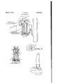
- Fig. .1 is an elevational viewer a wheelsuspen- I sion systemembodying myinvention
- Fig. 2 is a sectional view taken on the line '2-2 of Fig. 1;
- Fig. 3 is a plan view of the portion of the suspension system embodying my invention taken on the line 3 3 of Fig. 1;
- Fig. 4 is an elevational View of a modilied form of the shafts and collar assembly shown in Figs.
- the frame IB is of the conventional c'onstruction 'having a pair of upwardly extending Vbrackets l2 for pivotally receiving one extremity of an ⁇ upper control arm i3.
- the crossmember 'lil has pivotally -mounted on its underside one extremity of lower control arm lll.
- the upper control arm i3 and the lower control arm M are pivotally connected Lat their other extremities by an :upright knuckle bracket l5 which has a motor ⁇ vehicle wheel l5 mounted thereon by means of -a kingpin and spindle assembly ll.
- the frame l! has an upper plate i8 welded thereto for receiving and positioning the upper .extremity of a coil spring i9.
- the vlower extremity of the spring I9 is seated in ya lower plate '20 which is welded to the lower control arm I4.
- the wheel is suspended from the frame and .cross member assembly since one extremity of the spring is mounted ⁇ on the frame and the other extremity of the spring is ⁇ mounted on the 'lower lcontrol arm which is pivoted to the .cross member. It would then be proper to refer to the frame Il!
- a shock absorber generally designated by the numeral 2l of the conventional type having a casing 22 forming a reservoir for fluid medium such :as oil, is mounted on the upper plate I8 iby la bracket 22 which is secured to the casing or relatively .stationary portion of the shock absorber.
- a piston rod ⁇ 23 extends into the cas; ing 22 and has a piston ⁇ 23 on its lower end.
- the upper end of the piston rod 23 is threaded in an aperture of a collar 24 which has a pair of threaded studs 25 extending outwardly in opposite Vdirections therefrom.
- the studs 25 are adapted vto be received in apertures formed in one extremity of a pair of rods 26 which extend downwardly from Athe collar 24 to the lower plate 2li.
- the other extremities of the rods 26 are yieldably connected to the lower plate 2li .by washers 21 and 2l' comprising rubber or synthetic rubberlike material.
- the upper washer 2l is positioned between the lower plate 20 and an upper yoke-shaped member 28, the latter being prevented from upward movement by the shoulder 29 formed in the rod 26.
- the lower washer 21 is positioned between the lower plate 20 and a lower yokeshaped member 30, the latter being held in position by a nut 3l threaded on the lower extremity of the rod 26.
- These washers must be so constructed and positioned to allow a predetermined amount of movement of the shafts 26 relative to the lower plate 20. This movement is necessary because the angle of juncture of the shafts and the lower plate is slightly changed when the lower control arm is pivoted. By utilizing the yieldable qualities of the washers the shafts are allowed this movement while being securely retained to the lower plate.
- Fig. 4 I have shown a modification of the collar 24 and rods 25 in which these parts of the structure are formed of one continuous and integral piece of metal. This construction is advantageous in that it is inexpensive to manufacture.
- both the rods 25 and the shock absorber 2l are positioned within the coil spring I9.
- the shock absorber By so positioning these elements a more compact structure is obtained and the main portions of the shock absorber are protected by the spring from injury by stones and other objects. Also by mounting the shock absorber in this fashion, the cost of manufacture is greatly reduced because the same parts are used to mount the coil spring I8, as are also used to mount the shock absorber and rods.
- the wheel During motion of a motor vehicle, the wheel is continually moved or vibrated in a vertical direction relative to the frame as the wheel encounters road irregularities. As this occurs, the lower control arm I4 pivots about its connection with the cross member Il, thereby causing the shafts 25 to actuate the piston rod 23 inwardly and outwardly of the shock absorber.
- the frame and cross member assembly has comparatively little vertical motion as compared to the vertical motion of the Wheel, therefore, since the reservoir section of the shock absorber is mounted on this sprung portion, the medium therein will remain in a comparatively unmixed or unchurned state.
- a suspension assembly comprising upper and lower members pivotally mounted on said frame means, a projection secured to said frame means and extending outwardly therefrom, a coil spring operatively disposed between said projection and said lower member, a hydraulic shock absorber having a reservoir portion and a piston rod extending out of said reservoir portion, said reservoir portion being secured to said projection and depending within said coil spring, a pair of rods disposed Within said spring and secured between said piston rod and said lower member, and means associated with said pair of rods for accommodating movement thereof relative to said lower member.
- a suspension assembly comprising upper and lower members pivotally mounted on said frame means, a projection secured to said frame means and extending outwardly therefrom, a coil spring operatively disposed between said projection and said lower member, a hydraulic shock absorber having a reservoir portion and a piston rod extending out of said reservoir portion, said reservoir portion being secured to said projection and depending within said coil spring, a pair of rods disposed within said spring and secured between said piston rod and said lower member, and means associated with said pair of rods for accommodating tilting movement thereof relative to said frame means.
- a suspension system connected between said portions comprising upper and lower control arms pivotally connecting said sprung and unsprung portions, a plate secured to said sprung portion and extending outwardly therefrom, a coil spring disposed between said plate and said lower control arm, a hydraulic shock absorber having a reservoir portion secured to said plate, said absorber having an actuating rod extending outwardly thereof above said plate, a collar secured to said actuating rod and having projections extending outwardly therefrom, a pair of rods extending through said coil spring and connected between projections on said collar and said lower control arm, and means associated with said last mentioned pair of rods for accommodating tilting movement thereof relative to said sprung portion.
- a suspension system connected between said portions comprising upper and lower control arms pivotally connecting said sprung and unsprung portions, a plate secured to said sprung portion and extending outwardly therefrom, a coil spring disposed between said plate and said lower control arm, a hydraulic shock absorber having a reservoir portion secured to said plate, said absorber having an actuating rod extending outwardly thereof above said plate, a collar secured to said actuating rod and having projections extending outwardly therefrom, a pair of rods extending through said coil spring and connected between the projections on said collar and said lower control arm, and yieldable means associated with said last mentioned pair of rods for accommodating movement thereof relative to said lower control arm.
Landscapes
- Engineering & Computer Science (AREA)
- Mechanical Engineering (AREA)
- Vehicle Body Suspensions (AREA)
Description
N. WYETH SHOCK ABSORBER March 6, 1951 Filed Nov. 20, 1947 :UNITED ESTATES Patented Mar. 6, 1951 `Application November 20, y1947, Serial No. 787,093
'TENT IOFFHCEE.Y
.4 Claims. (Cl. 267-8) My invention relates to `motor vehicles :and
more particularly to shock absorber :assemblies `on motor vehicles.
In the past the shock absorber has been mounted `at its reservoir end on the unsprung,
movable members vof the wheel `suspension of a motor vehicle. When the :shock absorber is mounted in this manner, :the liquid medium in the lower portion of the reservoir was excessively mixed or Ychurned with the airv in the upper portion lof the .reservoir 'when excessive vertical motion of the wheeloccurred producing a mixture of air and liquid, .suol-1 as-oil. Under these conditions the shock absorber does Anot y.operate satisfactorily because :the .air of thenlixture -is compressible by the :piston of the shock and `the piston is `moved quickly toward :its lower position thus defeating the purpose of y.theshock absorber. 'The same action takes place npon `.opposite.movement of the `piston of a double acting vshock absorber when the :latter :isso .mounted that its `iluid is mixed with air duetto excessive 'vibratory movement.
:The principal object of my lirn/ention is to provide a .motor vehicle with .a shock absorber which has a fluid reservoir .mounted directly on the spring portion of the vehicle "thereby greatly reducing the vertical and other motion of the Afluid reservoir.
.Another object of my invention is ito provide vide a motor vehicle witha shock absorber which is partially mounted within'the coil spring ofthe suspension `system .of the vehicle thereby utilizing the space within .the spring and thus lprotecting aflargeportionof `the shock absorber from stones andthe like.
Other objects and advantages will become more apparent from the following description taken in connection with the accompanying drawings in which:
Fig. .1 is an elevational viewer a wheelsuspen- I sion systemembodying myinvention;
Fig. 2 is a sectional view taken on the line '2-2 of Fig. 1;
Fig. 3 is a plan view of the portion of the suspension system embodying my invention taken on the line 3 3 of Fig. 1;
Fig. 4 is an elevational View of a modilied form of the shafts and collar assembly shown in Figs.
lll)
'1, 2 and 3. i
Referring now to the drawings, I have shown a motor vehicle frame lo having a cross member H. The frame IB is of the conventional c'onstruction 'having a pair of upwardly extending Vbrackets l2 for pivotally receiving one extremity of an `upper control arm i3. The crossmember 'lil has pivotally -mounted on its underside one extremity of lower control arm lll. The upper control arm i3 and the lower control arm M are pivotally connected Lat their other extremities by an :upright knuckle bracket l5 which has a motor `vehicle wheel l5 mounted thereon by means of -a kingpin and spindle assembly ll. The frame l!) 'has an upper plate i8 welded thereto for receiving and positioning the upper .extremity of a coil spring i9. The vlower extremity of the spring I9 is seated in ya lower plate '20 which is welded to the lower control arm I4. By positioning the :spring in this manner, the wheel is suspended from the frame and .cross member assembly since one extremity of the spring is mounted `on the frame and the other extremity of the spring is `mounted on the 'lower lcontrol arm which is pivoted to the .cross member. It would then be proper to refer to the frame Il! and cross member fll as ythe sprung portion of a wheel suspension system and the remaining mechanism comprising the upper and lower control arms i3 and Hl, the upright knuckle bracket l5 the kingpin and spindle vassembly Il and the wheel i6 as the unlsprung portion of the wheel suspension system.
A shock absorber, generally designated by the numeral 2l of the conventional type having a casing 22 forming a reservoir for fluid medium such :as oil, is mounted on the upper plate I8 iby la bracket 22 which is secured to the casing or relatively .stationary portion of the shock absorber. A piston rod `23 extends into the cas; ing 22 and has a piston `23 on its lower end. The upper end of the piston rod 23 is threaded in an aperture of a collar 24 which has a pair of threaded studs 25 extending outwardly in opposite Vdirections therefrom. The studs 25 are adapted vto be received in apertures formed in one extremity of a pair of rods 26 which extend downwardly from Athe collar 24 to the lower plate 2li. The other extremities of the rods 26 are yieldably connected to the lower plate 2li .by washers 21 and 2l' comprising rubber or synthetic rubberlike material.
The upper washer 2l is positioned between the lower plate 20 and an upper yoke-shaped member 28, the latter being prevented from upward movement by the shoulder 29 formed in the rod 26. The lower washer 21 is positioned between the lower plate 20 and a lower yokeshaped member 30, the latter being held in position by a nut 3l threaded on the lower extremity of the rod 26. These washers must be so constructed and positioned to allow a predetermined amount of movement of the shafts 26 relative to the lower plate 20. This movement is necessary because the angle of juncture of the shafts and the lower plate is slightly changed when the lower control arm is pivoted. By utilizing the yieldable qualities of the washers the shafts are allowed this movement while being securely retained to the lower plate.
In Fig. 4 I have shown a modification of the collar 24 and rods 25 in which these parts of the structure are formed of one continuous and integral piece of metal. This construction is advantageous in that it is inexpensive to manufacture.
As more clearly seen in Fig. 2. both the rods 25 and the shock absorber 2l are positioned within the coil spring I9. By so positioning these elements a more compact structure is obtained and the main portions of the shock absorber are protected by the spring from injury by stones and other objects. Also by mounting the shock absorber in this fashion, the cost of manufacture is greatly reduced because the same parts are used to mount the coil spring I8, as are also used to mount the shock absorber and rods.
During motion of a motor vehicle, the wheel is continually moved or vibrated in a vertical direction relative to the frame as the wheel encounters road irregularities. As this occurs, the lower control arm I4 pivots about its connection with the cross member Il, thereby causing the shafts 25 to actuate the piston rod 23 inwardly and outwardly of the shock absorber. In the suspension system as heretofore described, it may be readily seen that the frame and cross member assembly has comparatively little vertical motion as compared to the vertical motion of the Wheel, therefore, since the reservoir section of the shock absorber is mounted on this sprung portion, the medium therein will remain in a comparatively unmixed or unchurned state.
Although but several embodiments of the invention are herein shown and described, it will be understood that various changes in the details of construction and materials employed may be made Without departing from the spirit of the invention.
I claim:
1. In a motor vehicle having a frame means, a suspension assembly comprising upper and lower members pivotally mounted on said frame means, a projection secured to said frame means and extending outwardly therefrom, a coil spring operatively disposed between said projection and said lower member, a hydraulic shock absorber having a reservoir portion and a piston rod extending out of said reservoir portion, said reservoir portion being secured to said projection and depending within said coil spring, a pair of rods disposed Within said spring and secured between said piston rod and said lower member, and means associated with said pair of rods for accommodating movement thereof relative to said lower member.
2. In a motor vehicle having a frame means, a suspension assembly comprising upper and lower members pivotally mounted on said frame means, a projection secured to said frame means and extending outwardly therefrom, a coil spring operatively disposed between said projection and said lower member, a hydraulic shock absorber having a reservoir portion and a piston rod extending out of said reservoir portion, said reservoir portion being secured to said projection and depending within said coil spring, a pair of rods disposed within said spring and secured between said piston rod and said lower member, and means associated with said pair of rods for accommodating tilting movement thereof relative to said frame means.
3. In a vehicle including a sprung portion and an unsprung portion, a suspension system connected between said portions comprising upper and lower control arms pivotally connecting said sprung and unsprung portions, a plate secured to said sprung portion and extending outwardly therefrom, a coil spring disposed between said plate and said lower control arm, a hydraulic shock absorber having a reservoir portion secured to said plate, said absorber having an actuating rod extending outwardly thereof above said plate, a collar secured to said actuating rod and having projections extending outwardly therefrom, a pair of rods extending through said coil spring and connected between projections on said collar and said lower control arm, and means associated with said last mentioned pair of rods for accommodating tilting movement thereof relative to said sprung portion.
4. In a vehicle including a sprung portion and an unsprung portion, a suspension system connected between said portions comprising upper and lower control arms pivotally connecting said sprung and unsprung portions, a plate secured to said sprung portion and extending outwardly therefrom, a coil spring disposed between said plate and said lower control arm, a hydraulic shock absorber having a reservoir portion secured to said plate, said absorber having an actuating rod extending outwardly thereof above said plate, a collar secured to said actuating rod and having projections extending outwardly therefrom, a pair of rods extending through said coil spring and connected between the projections on said collar and said lower control arm, and yieldable means associated with said last mentioned pair of rods for accommodating movement thereof relative to said lower control arm.
NATHANIEL WYETH.
REFERNCES CITED The following references are of record in the file of this patent:
UNITED STATES PATENTS Number Name Date 844,884 Mans Feb. 19, 1907 1,118,818 Sherman Nov. 24, 1914 1,737,328 Parisi Nov. 26, 1929 1,866,167 Lolley July 5, 1932 1,992,526 Funston Feb. 26, 1935 2,321,832 Leighton June 15, 1943 2,338,478 Wulff` Jan. 4, 1944 FOREIGN PATENTS Number Country Date 646,446 Germany June 14, 1937
Priority Applications (1)
| Application Number | Priority Date | Filing Date | Title |
|---|---|---|---|
| US787093A US2544548A (en) | 1947-11-20 | 1947-11-20 | Shock absorber |
Applications Claiming Priority (1)
| Application Number | Priority Date | Filing Date | Title |
|---|---|---|---|
| US787093A US2544548A (en) | 1947-11-20 | 1947-11-20 | Shock absorber |
Publications (1)
| Publication Number | Publication Date |
|---|---|
| US2544548A true US2544548A (en) | 1951-03-06 |
Family
ID=25140402
Family Applications (1)
| Application Number | Title | Priority Date | Filing Date |
|---|---|---|---|
| US787093A Expired - Lifetime US2544548A (en) | 1947-11-20 | 1947-11-20 | Shock absorber |
Country Status (1)
| Country | Link |
|---|---|
| US (1) | US2544548A (en) |
Cited By (2)
| Publication number | Priority date | Publication date | Assignee | Title |
|---|---|---|---|---|
| US2777112A (en) * | 1953-11-12 | 1957-01-08 | United Geophysical Corp | Magnetometer survey apparatus |
| US20230164481A1 (en) * | 2021-02-25 | 2023-05-25 | Panasonic Intellectual Property Management Co., Ltd. | Electrical device |
Citations (8)
| Publication number | Priority date | Publication date | Assignee | Title |
|---|---|---|---|---|
| US844884A (en) * | 1905-11-22 | 1907-02-19 | Albert Mans | Spring-recoil neutralizer. |
| US1118818A (en) * | 1914-03-24 | 1914-11-24 | David Morton Sherman | Shock-absorber. |
| US1737328A (en) * | 1926-08-19 | 1929-11-26 | Parisi Francesgo | Spring suspension for vehicle bodies |
| US1866167A (en) * | 1929-07-22 | 1932-07-05 | William H Lolley | Shock absorber |
| US1992526A (en) * | 1933-07-13 | 1935-02-26 | Gen Motors Corp | Shock absorber |
| DE646446C (en) * | 1935-02-08 | 1937-06-14 | Fiat Spa | Swing axis for motor vehicles formed from a four-bar linkage |
| US2321832A (en) * | 1941-06-21 | 1943-06-15 | John W Leighton | Individual wheel suspension |
| US2338478A (en) * | 1940-02-07 | 1944-01-04 | Wulff Siegfried | Independent wheel suspension |
-
1947
- 1947-11-20 US US787093A patent/US2544548A/en not_active Expired - Lifetime
Patent Citations (8)
| Publication number | Priority date | Publication date | Assignee | Title |
|---|---|---|---|---|
| US844884A (en) * | 1905-11-22 | 1907-02-19 | Albert Mans | Spring-recoil neutralizer. |
| US1118818A (en) * | 1914-03-24 | 1914-11-24 | David Morton Sherman | Shock-absorber. |
| US1737328A (en) * | 1926-08-19 | 1929-11-26 | Parisi Francesgo | Spring suspension for vehicle bodies |
| US1866167A (en) * | 1929-07-22 | 1932-07-05 | William H Lolley | Shock absorber |
| US1992526A (en) * | 1933-07-13 | 1935-02-26 | Gen Motors Corp | Shock absorber |
| DE646446C (en) * | 1935-02-08 | 1937-06-14 | Fiat Spa | Swing axis for motor vehicles formed from a four-bar linkage |
| US2338478A (en) * | 1940-02-07 | 1944-01-04 | Wulff Siegfried | Independent wheel suspension |
| US2321832A (en) * | 1941-06-21 | 1943-06-15 | John W Leighton | Individual wheel suspension |
Cited By (2)
| Publication number | Priority date | Publication date | Assignee | Title |
|---|---|---|---|---|
| US2777112A (en) * | 1953-11-12 | 1957-01-08 | United Geophysical Corp | Magnetometer survey apparatus |
| US20230164481A1 (en) * | 2021-02-25 | 2023-05-25 | Panasonic Intellectual Property Management Co., Ltd. | Electrical device |
Similar Documents
| Publication | Publication Date | Title |
|---|---|---|
| US1998477A (en) | Ring spring suspension for automobiles | |
| US5192100A (en) | Independent suspension with double isolated suspension unit | |
| US2935334A (en) | Motor vehicle wheel suspension | |
| US2621919A (en) | Wheel suspension | |
| FR1294372A (en) | Independent suspension device for motor vehicles or others | |
| US2169969A (en) | Stabilizer mechanism | |
| US2888269A (en) | Vehicle frame | |
| US2138114A (en) | Motor vehicle | |
| US2544548A (en) | Shock absorber | |
| US3155382A (en) | Independent front wheel suspension assembly | |
| US2320314A (en) | Differential spring suspension for vehicles | |
| US2896938A (en) | Vehicle suspension device | |
| US2833552A (en) | Dynamic vibration damper | |
| GB539720A (en) | Improvements relating to the damping of motor-vehicle suspensions | |
| US2460725A (en) | Springing arrangement for tractor-trailers | |
| US3195918A (en) | Vehicle suspension construction having resilient spring seat | |
| US3357718A (en) | Longitudinal-elasticity wheel mounting of vehicle | |
| US2548167A (en) | Shock absorber mounting | |
| US2731257A (en) | Independent vehicle wheel suspensions | |
| US2466345A (en) | Control for seat structure | |
| US2082620A (en) | Individual wheel-suspension for vehicles | |
| US2201250A (en) | Motor vehicle | |
| US1940330A (en) | Shock absorbing mounting | |
| US2667346A (en) | Suspension | |
| US2601886A (en) | Resiliently mounted vehicle seat |